Keating Of Chicago 2006 Series Manual
Incredible frying machine gas fryer
Hide thumbs
Also See for 2006 Series:
- User manual (43 pages) ,
- Manual (36 pages) ,
- User manual (42 pages)
Table of Contents
Advertisement
Quick Links
Download this manual
See also:
User Manual
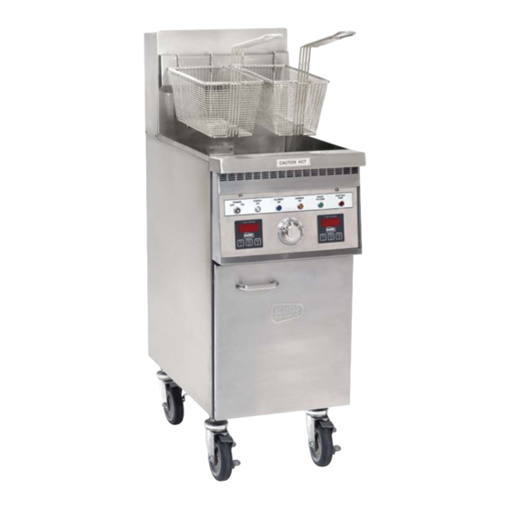
INCREDIBLE FRYING MACHINE™
GAS FRYER
SERIES 2006
MANUAL
IMPORTANT:
THE USER'S MANUAL PROVIDES SPECIFIC OPERATING INSTRUCTIONS
FOR YOUR MODEL. USE THE INCREDIBLE FRYING MACHINE™ ONLY AS
INSTRUCTED IN THIS MANUAL.
KEEP A COPY OF YOUR BILL OF SALE.
The date on the bill establishes the warranty period should service be required.
If service is performed, it is in your interest to obtain and keep all receipts.
KEEP THIS MANUAL FOR TRAINING NEW PERSONNEL.
Record the Serial number and Model number of this Incredible Frying Machine™ in
the spaces provided. Keep these numbers for future reference.
Keating commercial fryers are not intended for household use.
As continuous product improvement occurs, specifi cations may be
changed without notice.
1-800-KEATING | keatingofchicago.com
SERIAL NUMBER
MODEL NUMBER
Part # 017411
IfmGas2006_2013
11/13
Advertisement
Table of Contents

Related Manuals for Keating Of Chicago 2006 Series


Summary of Contents for Keating Of Chicago 2006 Series
- Page 1 Record the Serial number and Model number of this Incredible Frying Machine™ in the spaces provided. Keep these numbers for future reference. SERIAL NUMBER MODEL NUMBER Keating commercial fryers are not intended for household use. As continuous product improvement occurs, specifi cations may be changed without notice. 1-800-KEATING | keatingofchicago.com...
-
Page 2: For Your Safety
PURCHASER SHOULD POST IN A PROMINENT LOCATION INSTRUCTIONS TO BE FOLLOWED IN THE EVENT THE USER SMELLS GAS. THIS INFORMATION SHALL BE OBTAINED BY CON- SULTING THE LOCAL GAS SUPPLIER. WARNING Burns Shock Improper installation, adjustment, alteration, service or maintenance can cause property damage, injury or death. -
Page 3: Table Of Contents
INTRODUCTION Instructions in this manual should be read thoroughly before attempting to operate this Keating Gas Fryer. All installation and service on Keating equipment must be performed by qualifi ed, certifi ed, licensed and/or authorized installation or service personnel. Operating information for Keating equipment has been prepared for use by qualifi ed and/or authorized personnel. -
Page 4: Standard Features
Keating’s Incredible Frying Machine® (IFM) is de- STANDARD ACCESSORIES signed to give maximum production effi ciency, deliver- • Keating Klenzer Sample ing high quality food products. The following design • Drain clean out rod features are incorporated in Keating’s Incredible Frying Machine®... - Page 5 INCREDIBLE FRYING MACHINE™ - SERIES 2006 • Keating fryers are designed to operate on the • NEVER introduce objects or liquids into fryer, while gas fuel specified on the serial plate and must not operational, which are not designed or made for be operated with another gas fuel.
-
Page 6: First Steps
When pressure testing at test f disconnection of the restraint is necessary, it must pressures above 1/2 psig (3.45 KPA), fryer must be be reconnected when the Keating IFM is returned to disconnected from gas supply piping system. its originally installed position. -
Page 7: Gas Pressure Tap
The gas pressure tap is available on batteried fry- cesses will continue 3 times) ers with common manifold piping manufactured after 8/19/10. Keating batteries are often equipped with a common manifold that supplies gas to each product IF DISCONNECTION OF THE RESTRAINT IS NEC-... -
Page 8: Gas Leak Testing
“Max” line. NOTE: It is estimated that half of all service calls made LIGHTING on Keating Incredible Frying Machine® (IFM) result from an inadequate gas supply. During installation, have a gas company representative make certain that the fryer... -
Page 9: Cooking
STEP 1 operated. COOKING Keating Incredible Frying Machine® Gas Fryers (IFM) are designed to provide maximum production effi cien- cy and deliver high quality food products. Low - temperature cooking, highly polished stainless Make certain power to the timer has been OFF for at steel and a true COLD ZONE mean extended oil life. -
Page 10: Draining
To cancel a cycle in progress press and hold any but- ton for approximately two seconds. The relay output Figure 7 contacts will open and the display will show the time Keating Klenzer setting for the cook time last used. and Sea Powder keatingofchicago.com... -
Page 11: Preventative Maintenance
INCREDIBLE FRYING MACHINE™ - SERIES 2006 When cleaning and boiling out your fryer use Keating Sea Powder and Keating Klenzer to keep your fryer WATER IN ANY FORM AND HOT OIL DON'T MIX! in top condition. Keating Sea Powder dissolves any 15. -
Page 12: Oil Breakdown
10" WC for Propane at the manifold), use an by thermostat bulb positioning. allen wrench to remove the gas pressure test port, Keating’s patented thermostat application is accurate located in the center of the manifold. within 2°F of the dial setting between 250°F – 350°F. - Page 13 3. Apply oil resistant fl exible sealant on to compres- sion fi tting thread before installing fi tting into fryer vessel. 4. Position bent portion of bulb against far right heat transfer tube and install compression fi tting snugly into fryer vessel. 1-800-KEATING...
-
Page 14: Self Help Guide
2-1/2 to 3 minutes. Each cycle will last 15-25 seconds, ensuring that the temperature setting is held within a nar- row band. • Every Keating Incredible Frying Machine™ (IFM) has a number of safety controls to ensure safe operation and guard against component failure. -
Page 15: Service Diagnosis
SERVICE DIAGNOSIS The following diagnosis is only to be used as a guide to qualifi ed service personnel. Keating recommends that you use a qualifi ed & licensed service company. (Equipment still under warranty requires it.) Call 1-800-KEATING if you need assistance in locating a qualifi ed service company. -
Page 16: Cleaning And Boil-Out
PROBLEM PROBABLE CAUSE SOLUTION Delayed ignition a. Spark electrode gap is incorrect. a. Set proper gap on electrode (See detail on Page 27). b. Gas pressure excessive (incoming or b. Set pressure to serial plate. manifold). c. Replace spark module. c. -
Page 17: Ordering Parts
ORDERING PARTS Parts may be ordered by calling 1-800-KEATING or your local Keating service company. You may also order on-line at Keating’s part store, www.keatingofchicago.com Refer to the Keating Gas Fryer Limited Warranty for complete service and ordering information. -
Page 18: Parts List
030862 18" & 20" BLOWER 053726 INSULATION 052471 AIR HOSE 054162 CLAMP 1/2" WIDE BAND 13/16 x 1-1/2" 015393 FRY POT 1-800-KEATING PILOT TEE 020717 PILOT TUBING 1/8 S/S 022031 ELBOW BRASS 90° 016231 BUSHING 015390 14" ORIFICE #29 016502 18"... - Page 19 INCREDIBLE FRYING MACHINE™ GAS FRYER REAR DRAIN - MODEL 2000 (Corresponds with Parts List on Page 16) FRONT VIEW SIDE VIEW Oil Return Piping Assembly (Enlarged View) Burner & Electrode Assembly See Detail on Page 27 *Not shown See pages 21-22 for Control Panel Parts List 1-800-KEATING...
- Page 20 BLOWER 053726 AIR HOSE 1.25" ID 9" LONG 057996 CLAMP 1/2" WIDE BAND 13/16 x 1-1/2" 015393 FRY POT 1-800-KEATING PILOT TEE 006474 TUBING S/S 3/16" x 1" 037549 FLEX TUBING 1/4" S/S 6" LONG 054205 FITTING COMPRESSION 1/4" - 3/16 REDUCTION 037543 FLEX TUBING 1/4"...
- Page 21 INCREDIBLE FRYING MACHINE™ - SERIES 2006 INCREDIBLE FRYING MACHINE™ GAS FRYER FRONT DRAIN - MODEL 2006 (Corresponds with Parts List on Page 18) SIDE VIEW FRONT VIEW (See pages 23-26 for Control Panel Parts List) 1-800-KEATING...
- Page 22 INCREDIBLE FRYING MACHINE® GAS FRYER ASSEMBLY FRONT DRAIN (For reference only) FLUE FLUE FRY POT with Front Drain INSULATION HI-LIMIT BURNER MOUNTING BRACKET CENTER TUBE DIVIDER THERMOSTAT CENTER TUBE COVER PLATE BURNER ASSEMBLY (Page 25) keatingofchicago.com...
- Page 23 FEMALE PINS 028308 SNAP-IN BUSHING 1" 005664 TERMINAL BOARD WITH INSULATION 004153 12 CIRCUIT QUICK CONNECT MALE 028306 MALE PINS 028309 HIGH LIMIT (RESETTABLE) 034357 STRAIN RELIEF BUSHING 000430 POWER CORD 120V 9 FT. 006311 *Not available on all models 1-800-KEATING...
- Page 24 IFM CONTROL PANEL PARTS LIST (WITH TIMERS) MODEL 2000 Back Panel (Front View) Back Panel (Top View) ITEM DESCRIPTION POWER SWITCH W/GREEN LIGHT (REPLACEMENT KIT) 058328 POWER SWITCH WITHOUT LIGHT 035030 INDICATING LIGHT BLUE 015120 INDICATING LIGHT AMBER 021254 INDICATING LIGHT GREEN 021255 INDICATING LIGHT RED 021209...
- Page 25 TERMINAL BOARD WITH INSULATION 004153 HIGH LIMIT (Resettable) 034357 STRAIN RELIEF BUSHING 000430 POWER CORD 120V 9FT. 006311 RELAY, 35 SECOND DELAY 24VAC 035080 SPARK IGNITION CABLES 037551 RELAY 35 SECONDS 058684 SAFETY SWITCH MAGNETIC REED 053777 *Not available on all models 1-800-KEATING...
- Page 26 INDICATING LIGHT RED ROUND 28V 057861 SPARK IGNITION MODULE 037550 TRANSFORMER STEPDOWN 24VAC 80VA 024032 CIRCUIT BREAKER, 3 AMP 1 POLE 250V 053338 HIGH LIMIT MANUAL RESET 1-800-KEATING BACK MOUNT 004341 BOTTOM MOUNT 034357 RELAY DPDT 24VAC 030844 TERMINAL BOARD WITH INSULATION 004153 THERMOSTAT 14"...
- Page 27 THERMOSTAT 14" MODEL 035574 THERMOSTAT 18 & 20" MODELS 035575 SPARK IGNITION ELECTRODE LEAD 24" 059303 HIGH LIMIT MANUAL RESET 1-800-KEATING BACK MOUNT BOTTOM MOUNT TRANSFORMER STEPDOWN 24VAC 80VA 024032 TERMINAL BOARD WITH INSULATION 004153 SPARK IGNITION MODULE IFM 24VAC...
- Page 28 IFM CONTROL PANEL PARTS LIST (FRONT DRAIN WITH TIMERS) MODELS 2007 TO 2009 - 18" & 20" Back Panel (Top View) Back Panel (Front View) ITEM DESCRIPTION SWITCH ROCKER ON-OFF DPST 035030 INDICATING LIGHT BLUE RECTANGULAR 28V 032828 INDICATING LIGHT AMBER RECTANGULAR 28V 021254 INDICATING LIGHT GREEN RECTANGULAR 28V 021255...
- Page 29 037859 SPARK ELECTRODE REPLACEMENT KIT NATURAL GAS 052562 052908 OBSERVATION WINDOW ASSEMBLY LENS 016101 COVER 015905 BURNER OUTER PLATE & ELBOW ASSEMBLY (LEFT OR RIGHT SIDE) 022158 BURNER TO PLATE SEALING GASKET 016505 BURNER TO TUBE SEALING GASKET 016504 1-800-KEATING...
- Page 30 BASKET LIFT POWER SUPPLY BOX & BASKET LIFT ASSEMBLY (not shown to scale) Basket Lift Power Supply Box Basket Lift Assembly Top View Side View Housing Top View Bottom View NOTES: 1. A minimum distance of 3/16" and maximum distance of 1/4" should be maintained when actuator is at full downward stroke.
-
Page 31: Wiring Diagrams
3. Route all wires so they lay fl at and are organized in appearance. 4. Tug test all wires connected to terminal board to ensure they are properly secured. Tug test all crimp on connectors in the same fashion. 1-800-KEATING... - Page 32 14 IFM 120V CONNECTION DIAGRAM - NO TIMERS, FRONT DRAIN - MODEL 2000 Control Panel Insert Control Panel Back keatingofchicago.com...
- Page 33 INCREDIBLE FRYING MACHINE™ - SERIES 2006 IFM - 120V CONNECTION DIAGRAM - TIMERS, FRONT DRAIN WITH LIGHTED ROCKER SWITCH - MODEL 2000 Control Panel Insert Control Panel Back 1-800-KEATING...
- Page 34 14 IFM - MODEL 2006 FRONT DRAIN WITHOUT LIGHTED ROCKER SWITCH keatingofchicago.com...
- Page 35 INCREDIBLE FRYING MACHINE™ - SERIES 2006 14 IFM - MODEL 2006 WITH SAFE AND EASY® FILTER 1-800-KEATING...
- Page 36 14 IFM - MODEL 2006 CPU BASKET LIFT FRONT DRAIN keatingofchicago.com...
- Page 37 INCREDIBLE FRYING MACHINE™ - SERIES 2006 18 & 20 IFM - MODEL 2006 FRONT DRAIN WITH LIGHTED ROCKER SWITCH 1-800-KEATING...
- Page 38 18 & 20 IFM - MODEL 2007 FRONT DRAIN WITHOUT LIGHTED ROCKER SWITCH keatingofchicago.com...
- Page 39 INCREDIBLE FRYING MACHINE™ - SERIES 2006 18 & 20 IFM - MODEL 2007 WITH SAFE AND EASY® FILTER WITHOUT LIGHTED ROCKER SWITCH 1-800-KEATING...
- Page 40 BOB EVANS IFM - 120V CONNECTION DIAGRAM - NO TIMERS, REAR DRAIN - MODEL 2006 WITH TOGGLE SWITCHES keatingofchicago.com...
- Page 41 INCREDIBLE FRYING MACHINE™ - SERIES 2006 IFM 120V CONNECTION DIAGRAM - TIMERS, FRONT DRAIN - MODEL 2006 WITH TOGGLE SWITCHES 1-800-KEATING...
-
Page 43: Service Information
SERVICE INFORMATION: If you have a service related question call 1-800 -KEATING. Please state the nature of the call; it will ensure speaking with the appropriate person. Have your serial and model number available when ordering parts. As continuous product improvement occurs, specifi cations may be changed without notice.
Need help?
Do you have a question about the 2006 Series and is the answer not in the manual?
Questions and answers