Sony RCP-920 Operation Manual
Remote control panel
Hide thumbs
Also See for RCP-920:
- Operating instructions manual (149 pages) ,
- Operation manual (50 pages)

Related Manuals for Sony RCP-920


Summary of Contents for Sony RCP-920
- Page 1 REMOTE CONTROL PANEL RCP-920 RCP-921 OPERATION MANUAL [Japanese/English] 1st Edition (Revised 2)
- Page 3 ........................4 ......................4 ..........................5 ........................5 ....................6 ............8 ......................9 ....................... 9 ................... 16 ..................17 ......................17 ................18 ....................20 ....................21 ........................26 ..............26 ..................38 ..........................39...
- Page 8 • •...
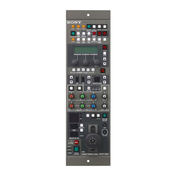
- Page 9 D EXT WORK KNEE DETAIL IRIS/MB ACTIVE MASTER IRIS SENS BLACK RELATIVE AUTO CLOSE OPEN COARSE IRIS RCP- REMOTE CONTROL PANEL...
- Page 10 AUTO SETUP SKIN DTL LEVEL START/ WHITE BLACK AUTO HUE BREAK...
- Page 13 • • • •...
- Page 29 • • •...
- Page 33 • • • •...
- Page 36 • •...
- Page 37 • •...
- Page 41 This equipment Pour les clients en Europe generates, uses, and can radiate radio frequency energy and, Le fabricant de ce produit est Sony Corporation, 1-7-1 Konan, if not installed and used in accordance with the instruction Minato-ku, Tokyo, Japon.
-
Page 42: Table Of Contents
Menu Configuration and Basic Operation ......56 Basic operation ................56 Basic configuration of menu pages ...........57 Menu transition diagram............59 Menu Items ................60 Initial Settings............... 65 Configuring the RCP-920/921 Operating Environment....65 Adjusting the LCD Display ..........76 Specifications ..............76 Table of Contents... -
Page 43: Precautions
The RCP-920 and RCP-921 are completely identical in their functions except with respect to the iris and master black adjustments. For the iris and master black adjustments, the RCP-920 uses a joystick type control while the RCP-921 uses rotary knobs. - Page 44 Camera SLS/ECS/shutter function control The SLS (Slow Shutter), ECS (Extended Clear Scan), and electronic shutter functions of the camera can be turned ON/OFF from this panel. The ECS frequency and shutter speed are also selected using the buttons on the panel. Dedicated cable or Ethernet connection The connection between the remote control panel and the camera control unit is established by a single dedicated...
-
Page 45: Examples Of System Configurations
CCU (1 to 6) HDCU1000 MSU-900 series (+HKCU1001/HKCU1003) CNU-700 RCP (1 to 6) HDC1000 HDCU1500 (+HKCU1001/HKCU1003) HDCU1000 (+HKCU1001/HKCU1003) HDC1500 HDCU1500 (+HKCU1001/HKCU1003) CCA-5 cable CCU/CNU CCU/CNU CCU/CNU CCU/CNU REMOTE REMOTE REMOTE REMOTE HDCU1000 (+HKCU1001/HKCU1003) HDC1500 RCP-920/921 HDCU1500 (+HKCU1001/HKCU1003) CCA-5 cable Overview... - Page 46 (Category 5 or higher) 1) Power over Ethernet About the switching hub power supply As the maximum power of the RCP-920/921 is 14 W, multiply 14 W by the number of connected RCP units when considering the power supply from the switching hub.
-
Page 47: Precautions For Ethernet System Connections
Attach the ground wire with the removed screw. Precautions for Ethernet System Connections When connecting the unit to the system with an Ethernet cable, make sure to ground the unit using one of the following methods. • Secure the flanges on the unit with screws. •... -
Page 48: Location And Function Of Parts
Master gain control block SHUTTER control block White balance/black balance control block Camera number/tally indication window NETWORK indicator Iris/master black control block (pages 53 and 54) RCP-920 CALL button PANEL ACTIVE button OPT indicators ALARM indicator RCP-921 Expanded camera/CCU function ON/OFF buttons... - Page 49 1 STANDARD button Note When you press this button, the video camera settings are The BARS button takes priority to the TEST button. If the initialized to the reference values stored on the video BARS button is lit, press the button to turn it dark before camera, and the button lights for several seconds.
- Page 50 6 Camera/CCU function ON/OFF buttons 7 Paint control block Various functions of the video camera or the CCU/HDCU can be turned ON and OFF from this panel. The following switching functions are assigned to seven of the buttons at the factory and the rightmost button is reserved for future use.
- Page 51 b STORE (scene file store) button Note To store a scene file, first press this button so that the Once you press any of the buttons 1 and 4, all the four button starts flashing, then press the SCENE FILES button buttons light, enabling both the ND and CC filter of the desired number.
- Page 52 b ABSOLUTE (absolute value mode) button Lit: Normal connection to the control device (CCU/ Press and light up this button to set the mode of manual HDCU) is established. adjustment with the WHITE, BLACK, FLARE, BLACK Flashing: There is no connection to the control device GAMMA, and DETAIL knobs from Relative mode to (CCU/HDCU).
- Page 53 Iris/master black control block (RCP-920) a EXT indicator b Spare button c AUTO button d IRIS/MB ACTIVE button e IRIS RELATIVE button i SENS control knob f IRIS display g MASTER BLACK j COARSE control knob RELATIVE button k Master black control ring...
- Page 54 Relative mode Absolute mode (IRIS RELATIVE button lit) (IRIS RELATIVE button out) IRIS lever (RCP-920) Adjusts the iris with relative values within 1/4 of Adjusts the iris within the variable range set by IRIS control knob the total range from OPEN to CLOSED.
-
Page 55: Connector Panel
Parts 1 through 0 have the same function as shown for ATTENTION the RCP-920. Par mesure de sécurité, ne raccordez pas le connecteur pour le câblage de périphériques pouvant avoir une tension k IRIS control excessive à ce port. Suivez les instructions pour ce port. -
Page 56: Menu Configuration And Basic Operation
Press the ENTER button once to go to the top page of the paint menu. Press the ENTER button again and hold it for at least The RCP-920/921 provides menu operations for various 1 second. The top page of the configuration menu functions such as adjustments of system equipment. -
Page 57: Basic Configuration Of Menu Pages
Basic configuration of menu pages Paint menu Top page Press to turn off the LCD. Shows a list of setting/ Press to go to the setting/adjustment page for the available selected item. adjustment When the LCD is off, press to turn on the display. items. - Page 58 Page with SET item For pages which have a “SET” item, changes must be confirmed by the setting procedure before they become active. Otherwise the changes will be lost when switching to another page. Example: ETHERNET IF page When you press ENTER once while the cursor is here, the cursor shape becomes “?.”...
-
Page 59: Menu Transition Diagram
Menu transition diagram POWER ON Menu Paint menu CLEAR ENTER ENTER Press and to switch pages hold ENTER (LCD panel OFF) Configuration menu The LCD display and backlight turn OFF. ENTER to switch pages CLEAR to switch pages Menu Configuration and Basic Operation... -
Page 60: Menu Items
Menu Items For details on the respective functions, see the operation manual of the connected camera or CCU. Paint menu Primary Secondary Operation/ Settings Function Factory default menu menu adjustment item TOP MENU — — — Lists items on the paint menu KNEE/GAMMA/FLARE/ SHUTTER/DETAIL/SAT KNEE... - Page 61 Primary Secondary Operation/ Settings Function Factory default menu menu adjustment item SD DTL Level — Adjusts SD detail level — Limit — Adjusts SD detail limit — Crisp — Adjusts SD detail crispening — AUTO IRIS Level — Adjusts auto iris level —...
- Page 62 Primary Secondary Operation/ Settings Function Factory default menu menu adjustment item VR REL WHITE Select from 1/1, Sets variable range for white balance 1/2, or 1/4 in Relative mode MODE SET BLACK (FLARE) Select from 1/1, Sets variable range for black (flare) 1/2, or 1/4 balance in Relative mode DETAIL...
- Page 63 Primary Secondary Operation/ Settings Function Factory default menu menu adjustment item ETHERNET ETHERNET ON/OFF Turns Ethernet connection ON/OFF AUTO NEGO ON/OFF Turns the Auto Negotiation function ON/OFF AUTO MDIX ON/OFF Turns the AUTO MDI/MDIX function ON/OFF 10M/100M Sets the connection speed 100M SPEED HALF/FULL...
- Page 64 Primary Secondary Operation/ Settings Function Factory default menu menu adjustment item TCP/IP IP ADDR — Shows assigned IP address — SETTING CONDITION SUBNET MASK — Shows configured subnet mask — (Continue) DEFAULT — Shows configured default gateway — GATEWAY 1) Can only be displayed or configured if ENGINEER is selected as MODE on SECURITY MODE screen. 2) RCP-921 only.
-
Page 65: Initial Settings
Operating Environment The RCP configuration menu allows you to configure Turn the right adjustment knob to change the setting settings on the RCP-920/921 such as the internal clock, item. buzzer volume, and LED and LCD brightness. To adjust the LCD You can adjust the brightness and contrast for the menu display panel. - Page 66 ENTER button. value The month setting flashes. You can change settings on the RCP-920/921 to change 4 Turn the right adjustment knob to change the the Step Shutter display to an angle value. month setting, and press ENTER button.
- Page 67 To change the output destination for units). previews (RCP-920) When you press the IRIS control lever/preview switch on the RCP-920, preview key signals are output. You can enable or disable the output settings for destinations individually. The output destinations you can configure are as follows.
- Page 68 To adjust the buzzer volume You can adjust the brightness of buttons and the LEDs in When a call signal is received on the RCP-920/921 or the the tally indication window on the RCP-920/921. panel is operated, the buzzer will emit a sound. You can adjust the buzzer volume as necessary.
- Page 69 3 Press ENTER button again to save the settings. The first screen of the RCP configuration menu reappears. To change the security mode The RCP-920/921 has an Engineer mode to limit access to Press CLEAR button. certain settings. These settings cannot be configured unless Engineer mode is enabled.
- Page 70 Press ENTER button to enable configuration. 1 Press ENTER button to enable configuration. The cursor appears as “?” and the START? display The cursor appears as “?” and the setting flashes. flashes. Turn the right adjustment knob to change the setting 2 Press ENTER button again.
- Page 71 SET in the upper right of the screen. To configure system connection settings 2 Press ENTER button to enable configuration. The RCP-920/921 supports system connections via the The cursor appears as “?.” CCU/CNU REMOTE connector and connections to camera network systems via the Ethernet connector.
- Page 72 3 Turn the right adjustment knob to select LEGACY, The CNS mode is set. and press ENTER button. Set the submode for Bridge mode. The CNS mode is set. In Bridge mode, you must configure the submode and target IP address to determine functioning. Under normal circumstances, set the RCP to ACTIVE or SEMI-AT.
- Page 73 4 Enter the entire IP address, and press ENTER button. The target IP address is set. Set the master IP address. The RCP-920/921 is always defined as a client in a multi-camera system, and the submode (Master/ Client) is automatically set to CLIENT. Save the system connection settings.
- Page 74 Press CLEAR button. The first screen of the RCP configuration menu reappears. To configure Ethernet connection settings The RCP-920/921 supports connections to camera 4 Enter the entire IP address, and press ENTER network systems via the Ethernet connector. Perform the button.
- Page 75 Use the v and V buttons to move through the settings SPEED: This is the connection speed setting for the and adjustment screens, and display the <ETHERNET Ethernet line. If Auto Negotiation is disabled, IF> page. manually configure this setting (10M or 100M) based on the devices to be connected.
-
Page 76: Adjusting The Lcd Display
While holding down the PARA and MASTER buttons, Dimensions (w/h/d, excluding projections) press the ENTER button on the paint control block. RCP-920/921: 102 × 310 × 67 mm The LCD display shows the following: (4 1/8 × 12 1/4 × 2 3/4 in) Dimensions (w/h/d, including projections) RCP-920: 102×310×125 mm... - Page 77 Specifications...
- Page 78 Specifications...
- Page 79 Ethernet is a registered trademark of Xerox Corporation. The material contained in this manual consists of information that is the property of Sony Corporation and is intended solely for use by the purchasers of the equipment described in this manual.
- Page 80 Sony Corporation Printed in Belgium RCP-920 (SY) 2008.06.08 RCP-921 (SY) 3-096-914-03(1) © 2006...