Table of Contents
Advertisement
Quick Links
SERVICE MANUAL
Ver 1.1 2002. 11
Front speakers
Speaker system
Speaker units
Enclosure type
Impedance
Power handling capacity
Maximum input power
Sensitivity level
Dimensions (w/h/d)
Mass
Cord length
Input impedance
Input
Subwoofer
Speaker system
Speaker unit
Enclosure type
Impedance
Power handling capacity
Maximum input power
Sensitivity level
Dimensions (w/h/d)
Mass
Amplifier section
Rated output:
Woofer section
Mid and high range section 3 W + 3 W <10 % T.H.D., 1 kHz, 6 Ω>
Total
Sony Corporation
9-873-998-02
2002K1600-1
Personal Audio Company
© 2002.11
Published by Sony Engineering Corporation
SPECIFICATIONS
Full range, magnetically shielded
3.9 cm, cone type
Bass reflex
6 Ω
3 watts
6 watts
81 dB (1 W, 1 m)
54 × 115 × 74 mm
210 g (Lch), 160 g (Rch)
2 m
4.7 kΩ (at 1 kHz)
LINE IN 1, 2
Active subwoofer, magnetically shielded
9 cm, cone type
Bass reflex
6 Ω
14 watts
28 watts
80 db (1 W, 1 m)
194 × 210 × 239 mm
2,400 g
14 W <10 % T.H.D., 100 Hz, 6 Ω>
20 W
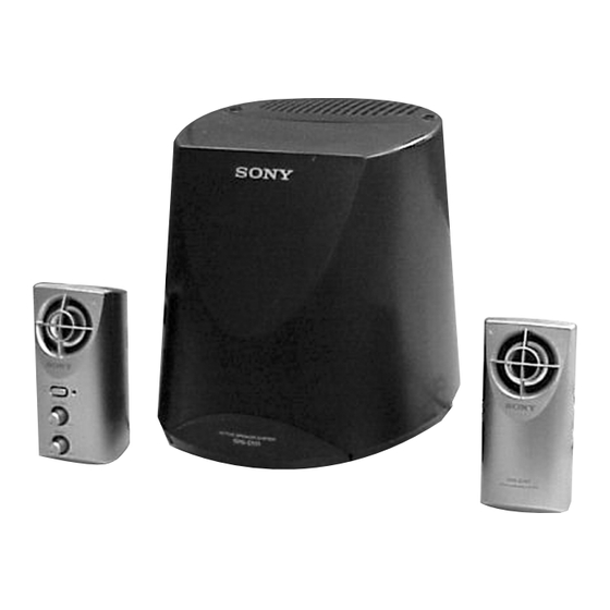
SRS-D101
Canadian Model
Australian Model
General
Power consumptions
Cord length
Where purchased
Operating voltage
U.S.A./Canada
120 V AC, 60 Hz
European countries
220-230 V AC, 50Hz
Other countries
• 110 – 120 V AC, 50/60Hz
• 220 – 230 V AC, 50 Hz
Supplied accessories
Audio connecting cord (1)
Design and specifications are subject to change
without notice.
ACTIVE SPEAKER SYSTEM
US Model
AEP Model
UK Model
E Model
20 W
2 m (adaptor cable)
Advertisement
Table of Contents

Related Manuals for Sony SRS-D101


Summary of Contents for Sony SRS-D101
- Page 1 14 W <10 % T.H.D., 100 Hz, 6 Ω> Woofer section Mid and high range section 3 W + 3 W <10 % T.H.D., 1 kHz, 6 Ω> Total 20 W ACTIVE SPEAKER SYSTEM Sony Corporation 9-873-998-02 2002K1600-1 Personal Audio Company © 2002.11 Published by Sony Engineering Corporation...
-
Page 2: Safety Check-Out
DIAGRAMMES SCHÉMATIQUES ET LA LISTE DES PIÈCES SONT CRITIQUES POUR LA SÉCURITÉ DE FONCTIONNEMENT. NE REMPLACER CES COMPOSANTS QUE PAR DES PIÈSES SONY 1. A commercial leakage tester, such as the Simpson 229 or RCA DONT LES NUMÉROS SONT DONNÉS DANS CE MANUEL OU WT-540A. -
Page 3: Section 1 General
SRS-D101 SECTION 1 This section is extracted from instruction manual. GENERAL Precautions Front (Right)/Avant (droite) Front (Left)/Avant (gauche) On safety Vorne (rechts)/Parte frontal (derecha) Vorne (links)/Parte frontal (izquierda) The nameplate indicating operating voltage, power consumption, etc. is located on the bottom exterior. -
Page 4: Section 2 Diagrams
SRS-D101 SECTION 2 DIAGRAMS • IC Block Diagrams IC301 LA4601N STBY Standby switching R-IN Output Predrive CH1 input R-OUT amplifier amplifier amplifier PRE-GND TSD protector POWER amplifier Predrive Output CH2 input L-OUT amplifier amplifier amplifier L-IN Pop noise prevention block Ripple filter P. - Page 5 SRS-D101 Ver 1.1 2002.11 2-1. Printed Wiring Board – AMP Section – L OUT J301 CONTROL BOARD CN102 (Page 6) AEP, UK, AUS IC301 IC302 IC303 (Page 7) • Semiconductor Location Ref. No. Location D301 Note on Printed Wiring Boards: IC301 •...
- Page 6 SRS-D101 2-2. Printed Wiring Board – CONTROL Section – IC101 IC102 Note on Printed Wiring Boards: AMPLIFIER BOARD • X : parts extracted from the component side. • b : Pattern from the side which enables seeing. J301 (Page 5)
- Page 7 SRS-D101 Ver 1.1 2002.11 2-3. Printed Wiring Board – POWER Section – AEP, UK, AUS AEP, UK, AUS • Semiconductor Location Ref. No. Location D901 D902 Note on Printed Wiring Boards: D903 • X : parts extracted from the component side.
- Page 8 SRS-D101 Ver 1.1 2002.11 2-4. Schematic Diagra – ALL Section – • See page 4 for IC Block Diagrams. Note on Schematic Diagram: • Voltages is dc with respect to ground under no-sig- • All capacitors are in µF unless otherwise noted. pF: nal (detuned) conditions.
-
Page 9: Section 3 Exploded Views
SRS-D101 Ver 1.1 2002.11 SECTION 3 EXPLODED VIEWS NOTE: • Items marked “*” are not stocked since they • Accessories are given in the last of this parts The components identified by mark 0 or are seldom required for routine service. Some list. -
Page 10: Speaker Section
SRS-D101 Ver 1.1 2002.11 3-2. Speaker Section SP101 supplied SP102 supplied supplied supplied supplied Ref. No. Part No. Description Remarks Ref. No. Part No. Description Remarks X-3382-051-1 CABINET (L) SUB ASSY, FRONT (US,CND,E92,SP) X-3382-052-1 CABINET (R) SUB ASSY, FRONT X-3382-214-1 CABINET (L) SUB ASSY, FRONT (AEP,UK,AUS) -
Page 11: Section 4 Electrical Parts List
SRS-D101 Ver 1.1 2002.11 SECTION 4 AMPLIFIER CONTROL ELECTRICAL PARTS LIST NOTE: • Due to standardization, replacements in the • SEMICONDUCTORS • COILS In each case, u: µ, for example: uH: µH parts list may be different from the parts uA...: µA... - Page 12 SRS-D101 Ver 1.1 2002.11 CONTROL POWER Ref. No. Part No. Description Remarks Ref. No. Part No. Description Remarks C131 1-126-963-11 ELECT 4.7uF 20.00% 50V R205 1-216-829-11 METAL CHIP 4.7K 1/16W C201 1-126-963-11 ELECT 4.7uF 20.00% 50V R206 1-216-829-11 METAL CHIP 4.7K...
-
Page 13: Power Switch
SRS-D101 Ver 1.1 2002.11 POWER POWER SWITCH Ref. No. Part No. Description Remarks Ref. No. Part No. Description Remarks D902 8-719-046-07 DIODE 2A02M ACCESSORIES D903 8-719-046-07 DIODE 2A02M ************ D904 8-719-046-07 DIODE 2A02M D905 8-719-046-07 DIODE 2A02M 1-770-019-11 ADAPTOR, CONVERSION PLUG 3P (UK) -
Page 14: Revision History
SRS-D101 REVISION HISTORY Clicking the version allows you to jump to the revised page. Also, clicking the version at the upper right on the revised page allows you to jump to the next revised page. Ver. Date Description of Revision 2002.05...
Need help?
Do you have a question about the SRS-D101 and is the answer not in the manual?
Questions and answers