HP Pavilion zx5000 Maintenance And Service Manual
Hewlett-packard notebook pc maintenance and service guide
Hide thumbs
Also See for Pavilion zx5000:
- Hardware manual (166 pages) ,
- Limited warranty (164 pages) ,
- Software manual (76 pages)
Table of Contents
Advertisement
Maintenance and Service
Guide
HP Pavilion zx5000 Notebook PC
HP Pavilion zv5000 Notebook PC
Compaq Presario R3000 Notebook PC Series
HP Compaq Business Notebook nx9100 Series
Document Part Number: 335402-003
July 2004
This guide is a troubleshooting reference used for maintaining
and servicing the notebook. It provides comprehensive
Information on identifying notebook features, components, and
spare parts, troubleshooting notebook problems, and performing
notebook disassembly procedures.
Advertisement
Table of Contents
Troubleshooting

Related Manuals for HP Pavilion zx5000


Summary of Contents for HP Pavilion zx5000
- Page 1 Maintenance and Service Guide HP Pavilion zx5000 Notebook PC HP Pavilion zv5000 Notebook PC Compaq Presario R3000 Notebook PC Series HP Compaq Business Notebook nx9100 Series Document Part Number: 335402-003 July 2004 This guide is a troubleshooting reference used for maintaining and servicing the notebook.
- Page 2 The information contained herein is subject to change without notice. The only warranties for HP products and services are set forth in the express warranty statements accompanying such products and services. Nothing herein should be construed as constituting an additional warranty. HP shall not be liable for technical or editorial errors or omissions contained herein.
-
Page 3: Table Of Contents
1 Product Description 1.1 Features ........1–3 1.2 Power Management. -
Page 4: Table Of Contents
3.1 Serial Number Location ..... . 3–2 3.2 Major Components— HP Pavilion zv5000 and zx5000 ....3–3 3.3 Major Components—HP Compaq Business Notebook nx9100 Series and Compaq Presario R3000 Series . -
Page 5: Table Of Contents
4 Removal and Replacement Preliminaries 4.1 Tools Required ......4–1 4.2 Service Considerations ..... . . 4–2 Plastic Parts. -
Page 6: Specifications
Contents 6 Specifications A Connector Pin Assignments B Power Cord Set Requirements General Requirements ......B–1 Country-Specific Requirements . -
Page 7: Product Description
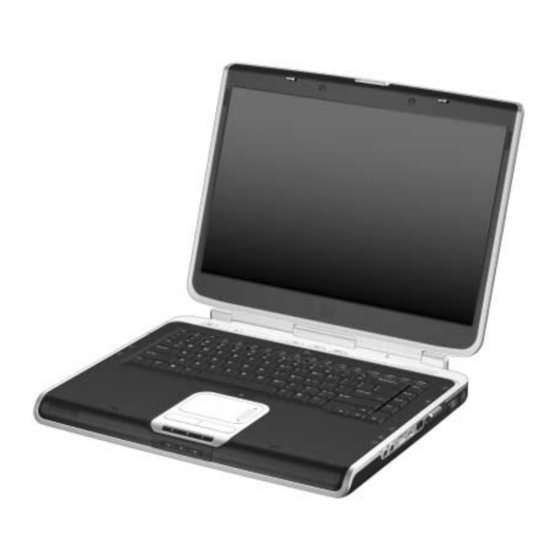
Product Description The HP Pavilion zv5000 and zx5000 notebook PCs, the HP Compaq Business Notebook nx9100 Series, and the Compaq Presario R3000 notebook PC offer advanced modularity; a 64-bit Mobile Intel® Pentium® 4 processor, 64-bit AMD Athlon 64 processor, or 32-bit AMD XP-M processor;... - Page 8 Product Description HP Pavilion zv5000 and zx5000 Notebooks HP Compaq Business Notebook nx9100 Series and Compaq Presario R3000 Notebooks 1–2 Maintenance and Service Guide...
-
Page 9: Features
1.1 Features ■ Mobile Intel Pentium 4 3.06-, 2.80-, 2.66-, and 2.40-GHz processors, all with 512-KB L2 cache, varying by notebook model - or - Intel Pentium 4 DT 3.20-, 3.06-, 2.80-, 2.66-, and 2.40-GHz processors, all with 256-KB L2 cache, varying by notebook model - or - AMD Athlon 64 1.8-, 2.0-, and 2.2-GHz processors, all with... - Page 10 Product Description ■ Integrated wireless support for Mini PCI 802.11a/b/g LAN devices ■ 2 Type II PC Card slots with support for both 32-bit (CardBus) and 16-bit PC Cards ■ External 120-watt AC adapter and power cord ■ 12- or 8-cell Li-Ion battery pack ■...
-
Page 11: Power Management
1.2 Power Management The notebook comes with power management features that conserve power and extend battery operating time. The notebook supports the following power management features: ■ Standby ■ Hibernation ■ User-customizable settings ■ Hotkeys for setting level of performance ■... -
Page 12: External Components
Product Description 1.3 External Components The external components on the front and right side of the HP Pavilion zv5000 and zx5000 notebooks are shown below and described in Table 1-1. Front and Right-Side Components—HP Pavilion zv5000 and zx5000 Notebooks 1–6... - Page 13 Front and Right-Side Components HP Pavilion zv5000 and zx5000 Notebooks Item Component Power/standby LED IDE (Integrated Drive Electronics) LED; also referred to as the hard drive/optical drive activity LED Display release latch Battery LED Stereo speakers (2) Volume increase button Increases system volume.
- Page 14 Product Description Front and Right-Side Components—HP Pavilion zv5000 and zx5000 Notebooks (Continued) 1–8 Maintenance and Service Guide...
- Page 15 Front and Right-Side Components HP Pavilion zv5000 and zx5000 Notebooks (Continued) Item Component Audio-out (headphone) jack Audio-in (microphone) jack USB port 1394 connector (select models) Infrared port (select models) Expansion port RJ-45 (network) jack S-Video jack Maintenance and Service Guide...
- Page 16 Product Description The external components on the front and right side of the HP Compaq Business Notebook nx9100 Series and Compaq Presario R3000 notebook are shown below and described in Table 1-2. Front and Right-Side Components—HP Compaq Business Notebook nx9100 Series and Compaq Presario R3000 Notebook 1–10...
- Page 17 Front and Right-Side Components HP Compaq Business Notebook nx9100 Series and Compaq Presario R3000 Item Component Stereo speakers (2) Power/standby LED Display release latch Battery LED IDE (Integrated Drive Electronics) LED; also referred to as the hard drive/optical drive activity LED...
- Page 18 Product Description Front and Right-Side Components—HP Compaq Business Notebook nx9100 Series and Compaq Presario R3000 (Continued) 1–12 Maintenance and Service Guide...
- Page 19 Front and Right-Side Components HP Compaq Business Notebook nx9100 Series and Compaq Presario R3000 (Continued) Item Component Audio-out (headphone) jack Audio-in (microphone) jack USB port 1394 connector (select models) Infrared port (select models) Vents (2) Maintenance and Service Guide Table 1-2...
- Page 20 The notebook rear and left-side components are shown below and described in Table 1-3. ✎ The notebook rear and left-side component locations are identical for the HP Pavilion zv5000 and zx5000, the HP Compaq Business Notebook nx9100 Series, and Compaq Presario R3000 Series. Notebook appearance varies by model.
- Page 21 Rear and Left-Side Components Item Component AC power connector Exhaust vent External monitor port Parallel connector RJ-11 (modem) jack (select models) Security cable slot Maintenance and Service Guide Table 1-3 Function Connects an AC adapter. Allows airflow to cool internal components. Ä...
- Page 22 Product Description ✎ The notebook rear and left-side component locations are identical for the HP Pavilion zv5000 and zx5000, HP Compaq Business Notebook nx9100 Series, and Compaq Presario R3000 models. Notebook appearance varies by model. Rear and Left-Side Components 1–16...
- Page 23 Holds a CD-ROM Drive, DVD-ROM Drive, DVD+RW/R and CD-RW Combo Drive, or DVD/CD-RW Combo Drive. ■ Digital Bay: Supports an optional pocket-sized HP USB Digital Drive. ■ Diskette Drive: Supports a standard 1.4-MB diskette. ■ No drive: No drive bay is installed.
- Page 24 The notebook keyboard components are shown below and described in Table 1-4. ✎ The notebook keyboard component locations are identical for the HP Pavilion zv5000 and zx5000, HP Compaq Business Notebook nx9100 Series, and Compaq Presario R3000 Series. Notebook appearance varies by model. Keyboard Components 1–18...
-
Page 25: Keyboard Components
Item Component fn key caps lock key f1 through f12 function keys num lock key Internal keypad Arrow keys Windows applications key Windows logo key Maintenance and Service Guide Table 1-4 Keyboard Components Function Combines with the function keys to perform additional system and application tasks. - Page 26 Product Description The top components of the HP Pavilion zv5000 and zx5000 notebooks are shown below and described in Table 1-5. Top Components—HP Pavilion zv5000 and zx5000 Notebooks 1–20 Maintenance and Service Guide...
-
Page 27: Top Components
HP Pavilion zv5000 and zx5000 Notebooks Item Component Power button Caps lock LED Num lock LED Picture button Media button Wireless button Internet button Maintenance and Service Guide Table 1-5 Top Components Function When the notebook is: ■ Off, press and release to turn on the notebook. - Page 28 Product Description Top Components—HP Pavilion zv5000 and zx5000 Notebooks (Continued) 1–22 Maintenance and Service Guide...
- Page 29 HP Pavilion zv5000 and zx5000 Notebooks (Continued) Item Component Display lid switch Exhaust vents (2) TouchPad button TouchPad LED TouchPad scroll area Left and right TouchPad buttons TouchPad 5-in-1 Memory Reader LED (select models) Maintenance and Service Guide Table 1-5...
- Page 30 Product Description The top components of the HP Compaq Business Notebook nx9100 Series and Compaq Presario R3000 are shown below and described in Table 1-6. Top Components—HP Compaq Business Notebook nx9100 Series and Compaq Presario R3000 1–24 Maintenance and Service Guide...
- Page 31 HP Compaq Business Notebook nx9100 Series and Compaq Presario R3000 Item Component Power button Caps lock LED Num lock LED Display lid switch TouchPad button TouchPad scroll area Left and right TouchPad buttons TouchPad TouchPad LED Maintenance and Service Guide...
- Page 32 Table 1-7. ✎ The notebook bottom component locations are identical for the HP Pavilion zv5000 and zx5000, HP Compaq Business Notebook nx9100 Series, and Compaq Presario R3000 Series. Notebook appearance varies by model. Bottom Components 1–26...
-
Page 33: Bottom Components
Item Component Exhaust vents (2) Fan vents (2) Hard drive bay Memory module compartment Battery release latch Battery bay Maintenance and Service Guide Table 1-7 Bottom Components Function Allow airflow to cool internal components. Ä To prevent overheating, do not obstruct vents. -
Page 34: Design Overview
Product Description 1.4 Design Overview This section presents a design overview of key parts and features of the notebook. Refer to to identify replacement parts, and Replacement Procedures,” board provides the following device connections: ■ Memory module ■ Mini PCI communications devices ■... -
Page 35: Troubleshooting
Troubleshooting Å WARNING: Only authorized technicians trained by HP should repair this equipment. All troubleshooting and repair procedures are detailed to allow only subassembly/module level repair. Because of the complexity of the individual boards and subassemblies, do not attempt to make repairs at the component level or modifications to any printed wiring board. -
Page 36: Computer Setup And Diagnostics Utilities
Troubleshooting 2.1 Computer Setup and Diagnostics Utilities The notebook features 2 system management utilities: ■ Computer Setup—A system information and customization utility that can be used even when your operating system is not working or will not load. This utility includes settings that are not available in Microsoft Windows. -
Page 37: Using Computer Setup
Using Computer Setup Information and settings in Computer Setup are accessed from the File, Security, or Advanced menus: 1. Turn on or restart the notebook. Press “f10 = ROM-Based Setup” message is displayed in the lower-left corner of the screen. ❏... -
Page 38: Selecting From The File Menu
Troubleshooting Selecting from the File Menu Select System Information Save to Floppy Restore from Floppy Restore Defaults Ignore Changes and Exit Save Changes and Exit 2–4 Table 2-1 File Menu To Do This ■ View identification information about the notebook, a port replicator, and any battery packs in the system. -
Page 39: Selecting From The Security Menu
Selecting from the Security Menu Select Setup Password Power-on Password DriveLock Passwords Password Options (Password options can be selected only when a power-on password has been set.) Device Security System IDs *Not applicable to SuperDisk LS-120 drives. Maintenance and Service Guide Table 2-2 Security Menu To Do This... -
Page 40: Selecting From The Advanced Menu
Troubleshooting Selecting from the Advanced Menu Select Language Boot Options Device Options 2–6 Table 2-3 Advanced Menu To Do This Change the Computer Setup language. Enable/disable: ■ QuickBoot, which starts the notebook more quickly by eliminating some startup tests. (If you suspect a memory failure and want to test memory automatically during startup, disable QuickBoot.) ■... - Page 41 Advanced Menu (Continued) Select Device Options (continued) HDD Self Test Options *Video modes vary even within regions. However, NTSC is common in North America; PAL, in Europe, Africa, and the Middle East; NTSC-J, in Japan; and PAL-M, in Brazil. Other South and Central American regions can use NTSC, PAL, or PAL-M.
-
Page 42: Using Diagnostics For Windows
You can display more or less information from anywhere within Diagnostics for Windows by selecting Level on the menu bar. Diagnostics for Windows is designed to test HP components. If third-party components are tested, the results might be inconclusive. -
Page 43: Diagnostic Test Information
Obtaining, Saving or Printing Diagnostic Test Information 1. Access Diagnostics for Windows by selecting Start > Settings > Control Panel > Diagnostics for Windows. 2. Select the Test tab. 3. In the scroll box, select the category or device you want to test. - Page 44 Troubleshooting 6. Select the Begin Testing button. 7. Select a tab to view a test report: ❏ Status tab—Summarizes the tests run, passed, and failed during the current testing session. ❏ Log tab—Lists tests run on the system, the number of times each test has run, the number of errors found on each test, and the total run time of each test.
-
Page 45: Troubleshooting Flowcharts
2.3 Troubleshooting Flowcharts Troubleshooting Flowcharts Overview “Flowchart 2.1—Initial Troubleshooting” “Flowchart 2.2—No Power, Part 1” “Flowchart 2.3—No Power, Part 2” “Flowchart 2.4—No Power, Part 3” “Flowchart 2.5—No Power, Part 4” “Flowchart 2.6—No Video, Part 1” “Flowchart 2.7—No Video, Part 2” “Flowchart 2.8—Nonfunctioning Port Replicator (if applicable)” “Flowchart 2.9—No Operating System (OS) Loading”... -
Page 46: Flowchart 2.1—Initial Troubleshooting
Troubleshooting Flowchart 2.1—Initial Troubleshooting Begin troubleshooting. Is there “Flowchart 2.2—No power? Beeps, LEDs, or error messages? Is there video? (no boot) “Flowchart 2.9—No Is the OS loading? Is there sound? 2–12 Go to Power, Part 1.” Check LED board, speaker connections. -
Page 47: Flowchart 2.2—No Power, Part 1
Flowchart 2.2—No Power, Part 1 No power (power LED is off). Remove from port replicator (if applicable). Power up on battery power? Power up on AC power? Power up in port replicator? 1. Reseat the power cables in the port replicator and at the AC outlet. -
Page 48: Flowchart 2.3—No Power, Part 2
Troubleshooting Flowchart 2.3—No Power, Part 2 Continued from “Flowchart 2.2—No Power, Part 1.” Visually check for debris in battery socket and clean if necessary. Power on? Check battery by recharging it, moving it to another notebook, or replacing it. Power on? Done 2–14 Done... -
Page 49: Flowchart 2.4—No Power, Part 3
Flowchart 2.4—No Power, Part 3 Continued from “Flowchart 2.3—No Power, Part 2.” Plug directly into AC outlet. Power LED on? Reseat AC adapter in notebook and at power source. Power on? Power outlet active? Replace power cord. Power on? Maintenance and Service Guide Done Done Internal or... -
Page 50: Flowchart 2.5—No Power, Part 4
Troubleshooting Flowchart 2.5—No Power, Part 4 Continued from “Flowchart 2.4—No Power, Part 3.” Open notebook. Loose or damaged parts? Close notebook and retest. Power on? Done 2–16 Reseat loose components and boards and replace damaged items. Replace the following items (if applicable) in the order given. -
Page 51: Flowchart 2.6—No Video, Part 1
Flowchart 2.6—No Video, Part 1 No video. Port replicator Stand-alone Port replicator? Stand-alone Internal or external display*? Internal External Adjust brightness. Video OK? Replace the following one at a time. Test after each replacement. Check for bent pins on cable. Video OK? Done Maintenance and Service Guide... -
Page 52: Flowchart 2.7—No Video, Part 2
Troubleshooting Flowchart 2.7—No Video, Part 2 Continued from “Flowchart 2.6—No Video, Part 1.” Remove notebook from port replicator, if connected. Adjust display brightness. Video OK? Check that notebook is properly seated in port replicator, for bent pins on cable, and for monitor connection. - Page 53 Flowchart 2.8—Nonfunctioning Port Replicator (if applicable) Nonfunctioning port replicator. Reseat power cord in port replicator and power outlet. Check voltage setting on port replicator. Reset monitor cable connector at port replicator. Port replicator operating? Remove notebook, reseat all internal parts, and replace any damaged items in port replicator.
-
Page 54: Loading
Troubleshooting Flowchart 2.9—No Operating System (OS) Loading No OS loading.* Reseat power cord in port replicator power outlet. *NOTE: Before beginning troubleshooting, always check cable connections, cable ends, and drives for bent or damaged pins. 2–20 No OS loading from hard drive, go to “Flowchart 2.10—No OS Loading, Hard Drive, Part 1.”... - Page 55 Flowchart 2.10—No OS Loading, Hard Drive, Part 1 OS not loading from hard drive. Nonsystem disk message? Reseat external hard drive. OS loading? Boot from Check the Setup utility for correct booting order. Boot from hard drive? Done Maintenance and Service Guide Go to “Flowchart 2.11—No OS...
-
Page 56: Flowchart 2.11—No Os Loading, Hard Drive, Part
Troubleshooting Flowchart 2.11—No OS Loading, Hard Drive, Part 2 Continued from “Flowchart 2.10—No OS Loading, Hard Drive, Part 1.” 1. Replace CD or diskette in 2. Replace system drive? Remove diskette and reboot. Boot from hard drive? Boot from diskette drive? Diskette Drive.”... - Page 57 Flowchart 2.12—No OS Loading, Hard Drive, Part 3 Continued from “Flowchart 2.11—No OS Loading, Hard Drive, Part 2.” System files on hard drive? Virus on hard drive? Run SCANDISK and check for bad sectors. Can bad sectors be fixed? Fix bad sectors.
-
Page 58: Diskette Drive
Troubleshooting Flowchart 2.13—No OS Loading, Diskette Drive OS not loading from diskette drive. Nonsystem disk message? Boot from another 2.17—Nonfunctioning device? Diskette drive enabled in the Setup utility? Is diskette drive boot order correct? Change boot priority using the Setup utility. 2–24 Reseat diskette drive. -
Page 59: Dvd-Rom Drive
Flowchart 2.14—No OS Loading, CD-ROM or DVD-ROM Drive No OS loading from CD-ROM or DVD-ROM Drive. Boots from CD or DVD? Reseat drive. Maintenance and Service Guide Disc in drive? Install Try another bootable disc. bootable disc. Done Boots from CD or DVD? Booting from another... -
Page 60: Flowchart 2.15—No Audio, Part 1
Troubleshooting Flowchart 2.15—No Audio, Part 1 No audio. Notebook in port replicator (if applicable)? Go to “Flowchart 2.16—No Audio, Part 2.” 2.17—Nonfunctioning 2–26 Turn up audio internally or externally. Undock Replace the following port replicator components one at a time, as applicable. Check audio status after each change. -
Page 61: Flowchart 2.16—No Audio, Part 2
Flowchart 2.16—No Audio, Part 2 Continued from “Flowchart 2.15—No Audio, Part 1.” Audio driver in OS configured? Correct drivers for application? Connect to external speaker. Audio? Maintenance and Service Guide Reload audio drivers. Load drivers and set configuration in OS. Replace audio board and speaker... -
Page 62: Flowchart 2.17—Nonfunctioning Device
Troubleshooting Flowchart 2.17—Nonfunctioning Device the notebook and inspect cables and plugs for Clear CMOS. Reattach device. Close notebook, plug in power, and reboot. Device boots properly? Done 2–28 Nonfunctioning device. Reseat device. Unplug the nonfunctioning device from bent or broken pins or other damage. Any physical device detected? Replace hard drive. -
Page 63: Flowchart 2.18—Nonfunctioning Keyboard
Flowchart 2.18—Nonfunctioning Keyboard Keyboard not operating properly. Connect notebook to good external keyboard. External device works? Reseat internal keyboard connector (if applicable). Done Maintenance and Service Guide Replace system board. Replace internal keyboard or cable. Replace system board. Troubleshooting Done 2–29... -
Page 64: Pointing Device
Troubleshooting Flowchart 2.19—Nonfunctioning Pointing Device Pointing device not operating properly. Connect notebook to good external pointing device. External device works? Reseat internal pointing device connector (if applicable). Done 2–30 Replace system board. Replace internal pointing device or cable. Replace system board. -
Page 65: Connection
Flowchart 2.20—No Network/Modem Connection No network or modem connection. Network or modem jack active? Digital line? NIC/modem configured in OS? Disconnect all power from the notebook and open. Reseat NIC/modem (if applicable). Maintenance and Service Guide Replace jack or have jack activated. -
Page 66: Illustrated Parts Catalog
Illustrated Parts Catalog This chapter provides an illustrated parts breakdown and a reference for spare part numbers and option part numbers. Maintenance and Service Guide 3–1... -
Page 67: Serial Number Location
Illustrated Parts Catalog 3.1 Serial Number Location When ordering parts or requesting information, provide the notebook serial number and model number located on the bottom of the notebook. Serial Number Location 3–2 Maintenance and Service Guide... -
Page 68: Hp Pavilion Zv5000 And Zx5000
Illustrated Parts Catalog 3.2 Major Components— HP Pavilion zv5000 and zx5000 Notebook Major Components—HP Pavilion zv5000 and zx5000 Maintenance and Service Guide 3–3... - Page 69 HP Pavilion zv5000 and zx5000 Notebooks Spare Parts: Notebook Major Components Item Description Display assemblies For use with HP Pavilion zx5000 notebook models 15.4-inch, WUXGA, with wireless antennae 15.4-inch, WUXGA, without wireless antennae 15.4-inch, WSXGA, with wireless antennae 15.4-inch, WSXGA, without wireless antennae 15.4-inch, WXGA, with wireless antennae...
- Page 70 Illustrated Parts Catalog Notebook Major Components—HP Pavilion zv5000 and zx5000 (Continued) Maintenance and Service Guide 3–5...
- Page 71 The Netherlands Front bezel HP Pavilion zx5000 models HP Pavilion zv5000 models Fan assemblies For use with HP Pavilion zx5000 “M10” models For use with HP Pavilion zx5000 “M9” models For use with HP Pavilion zv5000 models 3–6 Table 3-2 350187-081 People’s Republic...
- Page 72 Illustrated Parts Catalog Notebook Major Components—HP Pavilion zv5000 and zx5000 (Continued) Maintenance and Service Guide 3–7...
- Page 73 Illustrated Parts Catalog HP Pavilion zv5000 and zx5000 Notebooks Spare Parts: Notebook Major Components (Continued) Item Description Optical drives 24X Max DVD+R/RW and CD-RW Combo Drive 8X Max DVD-ROM Drive 24X Max DVD/CD-RW Combo Drive 24X Max CD-ROM Drive Miscellaneous Plastics Kit...
- Page 74 Illustrated Parts Catalog Notebook Major Components—HP Pavilion zv5000 and zx5000 (Continued) Maintenance and Service Guide 3–9...
- Page 75 For use with HP Pavilion zv51xxand zv52xx Series models (without infrared) For use with HP Pavilion zx5000 Series models (full featured) For use with HP Pavilion zx5000 Series models (without infrared) PC Card assembly (not illustrated) Hard drives 80-GB, 5400-rpm...
- Page 76 Illustrated Parts Catalog Notebook Major Components—HP Pavilion zv5000 and zx5000 (Continued) Maintenance and Service Guide 3–11...
- Page 77 AMD Athlon 64, 2.00-GHz AMD Athlon 64, 1.80-GHz AMD Athlon 32, 1.80-GHz AMD Athlon 32, 1.60-GHz Processor support bracket (not illustrated) For use with HP Pavilion zv5000 and zx5000 Series models For use with HP Pavilion zv51xx Series models 3–12 Table 3-2...
- Page 78 Illustrated Parts Catalog Notebook Major Components—HP Pavilion zv5000 and zx5000 (Continued) Maintenance and Service Guide 3–13...
- Page 79 Illustrated Parts Catalog HP Pavilion zv5000 and zx5000 Notebooks Spare Parts: Notebook Major Components (Continued) Item Description Base enclosure Battery packs 12-cell, Li-Ion, 14.8 V, 4.4-Ah High Capacity 12-cell, Li-Ion, 14.8 V, 6.6-Ah 8-cell, Li-Ion, 14.4 V, 4.4-Ah Thermal module (not illustrated) Cable Kit (not illustrated) 3–14...
-
Page 80: And Compaq Presario R3000 Series
Illustrated Parts Catalog 3.3 Major Components—HP Compaq Business Notebook nx9100 Series and Compaq Presario R3000 Series Notebook Major Components—HP Compaq Business Notebook nx9100 Series and Compaq Presario R3000 (Continued) Maintenance and Service Guide 3–15... - Page 81 15.0-inch, XGA, with wireless antennae 15.0-inch, XGA, without wireless antennae 14.1-inch, XGA, with antennae 14.1-inch, XGA, without antennae For use with HP Compaq Business Notebook nx9100 Series models 15.4-inch, WXGA, with antennae 15.4-inch, WXGA, without antennae 15.0-inch, XGA, with antennae 15.0-inch, XGA, without antennae...
- Page 82 Illustrated Parts Catalog Notebook Major Components—HP Compaq Business Notebook nx9100 Series and Compaq Presario R3000 (Continued) Maintenance and Service Guide 3–17...
- Page 83 Description Miscellaneous Plastics Kit (includes the following components): Strip covers For use with Compaq Presario R3000 Series models For use with HP Compaq Business Notebook nx9100 Series models 1394 bezel Heat sink cover Hard drive cover Memory module compartment cover...
- Page 84 Illustrated Parts Catalog Notebook Major Components—HP Compaq Business Notebook nx9100 Series and Compaq Presario R3000 (Continued) Maintenance and Service Guide 3–19...
- Page 85 Front bezels For use with Compaq Presario R3000 Series models with wireless button without wireless button For use with HP Compaq Business Notebook nx9100 models with infrared lens and wireless button with infrared lens, without wireless button without infrared lens, with wireless button...
- Page 86 Illustrated Parts Catalog Notebook Major Components—HP Compaq Business Notebook nx9100 Series and Compaq Presario R3000 (Continued) Maintenance and Service Guide 3–21...
- Page 87 Compaq Presario R3000 Series Spare Parts: Notebook Major Components (Continued) Item Description System boards For use with HP Compaq Business Notebook nx9100 and nx9110 models For use with HP Compaq Business Notebook nx9105 models For use with Compaq Presario R3200 and...
- Page 88 Illustrated Parts Catalog Notebook Major Components—HP Compaq Business Notebook nx9100 Series and Compaq Presario R3000 (Continued) Maintenance and Service Guide 3–23...
- Page 89 Illustrated Parts Catalog HP Compaq Business Notebook nx9100 Series and Compaq Presario R3000 Series Spare Parts: Notebook Major Components (Continued) Item Description Processors Mobile Intel Pentium 4, 3.06-GHz, 533-MHz Mobile Intel Pentium 4, 2.80-GHz, 533-MHz Mobile Intel Pentium 4, 2.40-GHz, 533-MHz Intel Pentium 4 DT, 3.20-GHz...
- Page 90 Illustrated Parts Catalog Notebook Major Components—HP Compaq Business Notebook nx9100 Series and Compaq Presario R3000 (Continued) Maintenance and Service Guide 3–25...
- Page 91 Spare Parts: Notebook Major Components (Continued) Item Description Heat sinks For use with HP Compaq Business Notebook nx9110 model and Compaq Presario R3001, R3002, and R3010 notebook models For use with HP Compaq Business Notebook nx9105 and Compaq Presario R3004 and R31xx notebook...
- Page 92 Illustrated Parts Catalog Notebook Major Components—HP Compaq Business Notebook nx9100 Series and Compaq Presario R3000 (Continued) Maintenance and Service Guide 3–27...
- Page 93 Battery packs 12-cell, Li-Ion, 14.8-V, 6.6-Ah 8-cell, Li-Ion, 14.4-V, 4.4-Ah Thermal module (not illustrated) For use with HP Compaq Business Notebook nx9110 model and Compaq Presario R3001, R3002, and R3010 notebook models For use with HP Compaq Business Notebook nx9105...
-
Page 94: Miscellaneous Plastics Kit Components
3.4 Miscellaneous Plastics Kit Components Miscellaneous Plastics Kit Components Miscellaneous Plastics Kit Components Spare Part Number 350206-001 for HP Pavilion zx5000 and zv5000 Series and Spare Part Number 350818-001 for HP Compaq Business Notebook nx9100 Series and Compaq Presario R3000 Series Item Description... -
Page 95: Mass Storage Devices
Illustrated Parts Catalog 3.5 Mass Storage Devices Spare Part Number Information Item Description Diskette drive For use with Pavilion zv5000 and zx5000 notebook models For use with HP Compaq Business Notebook nx9100 Series and Compaq Presario R3000 models Hard drives 80-GB, 5400-rpm... - Page 96 Spare Part Number Information (Continued) Item Description Optical Drives For use with Pavilion zv5000 and zx5000 notebook models 24X Max DVD+R/RW and CD-RW Combo Drive 8X Max DVD-ROM Drive 24X Max DVD/CD-RW Combo Drive 24X Max CD-ROM Drive For use with HP Compaq Business Notebook nx9100...
-
Page 97: Miscellaneous
For use with Presario R3000 Series For use with Presario R3200 Series For use with HP Business Notebook nx9110 models For use with Pavilion zx5000 Series and zv50xx notebook models For use with Presario R3001, R3002, and R3010 knobbed models... - Page 98 Screw Kit (includes the following screws; refer to Appendix C, “Screw Listing,” specifications and usage.) For use with HP Pavilion zx5000 Series and zv50xx notebook models, HP Compaq Business Notebook nx9110 model, and Compaq Presario R3001, R3002, and R3010 notebook models...
-
Page 99: Tools Required
Removal and Replacement This chapter provides essential information for proper and safe removal and replacement service. 4.1 Tools Required You will need the following tools to complete the removal and replacement procedures: ■ Magnetic screwdriver ■ Phillips P0 screwdriver ■ 5.0-mm socket for system board standoffs ■... -
Page 100: Service Considerations
Removal and Replacement Preliminaries 4.2 Service Considerations The following sections include some of the considerations to keep in mind during disassembly and assembly procedures. ✎ As you remove each subassembly from the notebook, place the subassembly (and all accompanying screws) away from the work area to prevent damage. -
Page 101: Preventing Damage To Removable Drives
4.3 Preventing Damage to Removable Drives Removable drives are fragile components that must be handled with care. To prevent damage to the notebook, damage to a removable drive, or loss of information, observe the following precautions: ■ Before removing or inserting a hard drive, shut down the notebook. -
Page 102: Preventing Electrostatic Damage
Removal and Replacement Preliminaries 4.4 Preventing Electrostatic Damage Many electronic components are sensitive to electrostatic discharge (ESD). Circuitry design and structure determine the degree of sensitivity. Networks built into many integrated circuits provide some protection, but in many cases the discharge contains enough power to alter device parameters or melt silicon junctions. -
Page 103: Packaging And Transporting Precautions
4.5 Packaging and Transporting Precautions Use the following grounding precautions when packaging and transporting equipment: ■ To avoid hand contact, transport products in static-safe containers, such as tubes, bags, or boxes. ■ Protect all electrostatic-sensitive parts and assemblies with conductive or approved containers or packaging. ■... -
Page 104: Workstation Precautions
Removal and Replacement Preliminaries 4.6 Workstation Precautions Use the following grounding precautions at workstations: ■ Cover the workstation with approved static-shielding material (refer to ■ Use a wrist strap connected to a properly grounded work surface and use properly grounded tools and equipment. ■... -
Page 105: Grounding Equipment And Methods
4.7 Grounding Equipment and Methods Grounding equipment must include either a wrist strap or a foot strap at a grounded workstation. ■ When seated, wear a wrist strap connected to a grounded system. Wrist straps are flexible straps with a minimum of one megohm ±10% resistance in the ground cords. - Page 106 Removal and Replacement Preliminaries Other grounding equipment recommended for use in preventing electrostatic damage includes: ■ Antistatic tape ■ Antistatic smocks, aprons, and sleeve protectors ■ Conductive bins and other assembly or soldering aids ■ Nonconductive foam ■ Conductive tabletop workstations with ground cords of one-megohm resistance ■...
-
Page 107: Typical Electrostatic Voltage Levels
Table 4-1 shows how humidity affects the electrostatic voltage levels generated by different activities. Typical Electrostatic Voltage Levels Event Walking across carpet Walking across vinyl floor Motions of bench worker Removing DIPS from plastic tube Removing DIPS from vinyl tray Removing DIPS from Styrofoam Removing bubble pack from PCB Packing PCBs in foam-lined box... -
Page 108: Removal And Replacement Procedures
Pavilion notebook. There are 65 screws, in 8 different sizes, that must be removed, replaced, or loosened when servicing the HP Compaq Business Notebook nx9100 Series or Compaq Presario R3000 Series. Make special note of each screw and standoff size and location during removal and replacement. -
Page 109: Serial Number
Removal and Replacement Procedures Serial Number Report the notebook serial number to HP when requesting information or ordering spare parts. The serial number is located on the bottom of the notebook. Serial Number Location 5–2 Maintenance and Service Guide... -
Page 110: Disassembly Sequence Chart
4 removed to disassemble 1 loosened 2 to remove 4 to disassemble 10 to remove Pavilion heat sink cover 11 to remove HP Compaq Business Notebook nx9100 Series and Compaq Presario R3000 heat sink cover 4 to remove heat sink... - Page 111 5.17 System board 5.18 Fan assembly 5–4 # of Screws Removed 8 on Pavilion 6 on HP Compaq Business Notebook nx9100 Series Compaq Presario R3000 8 on Pavilion 4 on HP Compaq Business Notebook nx9100 Series Compaq Presario R3000 5 screws and 4 standoffs on...
-
Page 112: Preparing The Notebook For Disassembly
For use with Pavilion notebook models 12-cell, Li-Ion, 14.8-V, 2.2-Ah 12-cell, Li-Ion, 14.8-V, 6.6-Ah 8-cell, Li-Ion, 14.4-V, 4.4-Ah For use with HP Compaq Business Notebook nx9100 Series and Compaq Presario R3000 Series models 12-cell, Li-Ion, 14.8-V, 6.6-Ah 8-cell, Li-Ion, 14.4-V, 4.4-Ah... - Page 113 Removal and Replacement Procedures 4. Remove the battery pack by following these steps: a. Turn the notebook upside down with the rear panel toward you. b. Slide and hold the battery release latch 1 toward you. The left side of the battery pack releases from the notebook. c.
- Page 114 Plastics Kit: spare part number 350206-001 for use with Pavilion notebook models, and spare part number 350818-001 for use with HP Compaq Business Notebook nx9100 Series and Compaq Presario R3000 Series models. Reverse the above procedure to install the battery pack and battery pack cover.
- Page 115 Removal and Replacement Procedures 5. Remove the hard drive by following these steps: a. Turn the notebook upside down with the rear panel toward you. b. Loosen the 2 PM2.5×6.0 captive screws 1 that secure the hard drive cover to the notebook. c.
- Page 116 The hard drive cover is included with the hard drive and also in the Miscellaneous Plastics Kit: spare part number 350206-001 for use with Pavilion notebook models, and spare part number 350818-001 for use with HP Compaq Business Notebook nx9100 Series and Compaq Presario R3000 Series models.
-
Page 117: Notebook Feet
Miscellaneous Plastics Kit: spare part number 350206-001 for use with Pavilion notebook models, and spare part number 350818-001 for use with HP Compaq Business Notebook nx9100 Series and Compaq Presario R3000 Series models. »... -
Page 118: Memory Module
5.5 Memory Module Memory modules 1024-MB 512-MB 256-MB 1. Prepare the notebook for disassembly 2. Turn the notebook upside down with the rear panel toward you. Maintenance and Service Guide Removal and Replacement Procedures Spare Part Number Information 350238-001 350237-001 370556-001 (Section 5.3). - Page 119 Removal and Replacement Procedures ✎ Steps 3 through 7 apply only to HP Pavilion zx5000 Series, HP Pavilion zv5000 Series, and HP Compaq Business Notebook nx9100 Series models. 3. Loosen the PM2.5×6.0 captive screw 1 that secures the memory module compartment cover to the notebook.
- Page 120 6. Spread the retaining tabs 1 that secure the memory module to the socket. The edge of the board opposite the edge connector rises up. 7. Pull the board away from the socket at a 45-degree angle 2. Removing a Memory Module Reverse the above procedure to install a memory module.
- Page 121 Removal and Replacement Procedures ✎ Steps 8 through 12 apply only to Compaq Presario R3000 Series models. 8. Loosen the PM2.5×6.0 captive screw 1 that secures the memory module compartment cover to the notebook. 9. Lift the left side of the memory module compartment cover up and swing it to the right 2.
- Page 122 11. Spread the retaining tabs 1 that secure the memory module to the socket. The edge of the board opposite the edge connector rises up. 12. Pull the board away from the socket at a 45-degree angle 2. Removing a Memory Module Reverse the above procedure to install a memory module.
-
Page 123: Combination Drive
Removal and Replacement Procedures 5.6 Combination Drive ✎ The combination drive consists of an optical drive and either an HP USB Digital Drive or a diskette drive. Diskette drive For use with Pavilion notebook models For use with HP Compaq Business Notebook... - Page 124 1. Prepare the notebook for disassembly 2. Turn the notebook upside down with the right side toward you. 3. Remove the 2 PM2.5×6.0 screws 1 that secure the combination drive to the notebook. 4. Slowly slide the drive out of the notebook 2 as far as the drive cable 3 will allow.
- Page 125 Removal and Replacement Procedures 5. Flip the drive over and rest it on the notebook 1. ✎ If the combination drive consists of an optical drive and a diskette drive, perform steps 6 and 7 to disconnect the flex cable from the drive. 6.
- Page 126 ✎ If the combination drive consists of an optical drive and an HP USB Digital Drive, perform steps 8 and 9 to disconnect the flex cable from the drive. 8. Release the zero insertion force (ZIF) connector 1 to which the drive cable is attached and disconnect the cable 2.
- Page 127 Removal and Replacement Procedures 10. To separate the optical drive from the HP USB Digital Drive or diskette drive, remove the 4 PM2.0×3.0 screws 1 that secure the drives together. 11. Separate the drives 2. Disassembling the Combination Drive Reverse the above procedure to reassemble and install the combination drive.
-
Page 128: Heat Sink
5.7 Heat Sink Heat sinks HP Pavilion zx5000 “M10” models HP Pavilion zx5000 “M9” models For use with HP Pavilion zv5000 Series, HP Compaq Business Notebook nx9110 model, and Compaq Presario R3001, R3002, and R3010 notebook models For use with HP Compaq Business Notebook... - Page 129 Removal and Replacement Procedures ✎ Steps 4 and 5 apply only to Pavilion notebook models. 4. Remove the 6 PM2.5×6.0 screws 1 and the 4 PM2.5×13.0 screws 2 that secure the thermal cover to the notebook. 5. Remove the thermal cover 3 from the notebook. Removing the Thermal Cover on Pavilion Notebook Models 5–22 Maintenance and Service Guide...
- Page 130 ✎ Steps 6 and 7 apply only to HP Compaq Business Notebook nx9100 Series and Compaq Presario R3000 Series notebook models. 6. Remove the 6 PM2.5×6.0 screws 1 and the 5 PM2.5×13.0 screws 2 that secure the thermal cover to the notebook.
- Page 131 Removal and Replacement Procedures 8. Remove the 4 PM2.5×11.0 spring-loaded shoulder screws that secure the heat sink to the notebook. Removing the Heat Sink Screws ✎ When reinstalling the heat sink screws, first start all 4 screws but do not tighten them. After all 4 screws are started, tighten each screw until the shoulder on the screw is fully seated against the screw post.
- Page 132 9. Use a flat-bladed screwdriver to turn the processor lock screw one-quarter turn counterclockwise to release the processor from the socket. Releasing the Processor on HP Compaq Business Notebook nx9100 Series and Compaq Presario R3000 Notebook Models Maintenance and Service Guide Removal and Replacement Procedures 5–25...
- Page 133 Removal and Replacement Procedures 10. Lift up on the right front corner of the heat sink 1 until it disengages from the notebook. 11. Slide the heat sink away from you 2, and then to the left 3 to clear the tabs on the heat sink from the notebook. 12.
-
Page 134: Processor
AMD Athlon 64, 1.8-GHz AMD Athlon 32, 1.8-GHz AMD Athlon 32, 1.6-GHz Processor support bracket (not illustrated) For use with HP Pavilion zv5000 and zx5000 Series models For use with HP Pavilion zv51xx Series models 1. Prepare the notebook for disassembly 2. - Page 135 Removal and Replacement Procedures ✎ Steps 5 and 6 apply only to notebook models with an AMD Athlon 64 or Athlon XP-M processor. 5. Press the processor lock lever slightly to the left to release it and then lift it up so that it rotates toward you to a 90-degree angle 1 to release the processor from the socket.
- Page 136 ✎ Steps 7 and 8 apply only to notebook models with a Mobile Intel Pentium 4 or Intel Pentium 4 processor. The processor was removed with the heat sink in Section 5.7 to avoid damaging the pins. 7. Align the processor so that the gold triangle 1 is in the lower- right corner.
-
Page 137: Strip Cover
Removal and Replacement Procedures 5.9 Strip Cover Strip covers For use with Pavilion notebook models, with wireless button For use with Pavilion notebook models, without wireless button For use with Presario notebook models For use with Business Notebook models 1. Prepare the notebook for disassembly 2. - Page 138 4. Turn the notebook right-side up with the front toward you. 5. Open the notebook display as far as possible. 6. Using a flat-bladed screwdriver, lift the right side 1 of the strip cover to disengage the cover 2 from the notebook. 7.
-
Page 139: Keyboard
Removal and Replacement Procedures 5.10 Keyboard Spare Part Number Information Keyboards Denmark Europe France Germany Greece Israel Italy The Netherlands 1. Prepare the notebook for disassembly 2. Remove the strip cover 5–32 350187-081 People’s Repubic 350187-021 of China 350187-051 Saudi Arabia 350187-041 Spain 350187-151... - Page 140 3. Remove the 4 PM2.5×3.0 screws 1 that secure the keyboard to the notebook. 4. Lift the rear edge of the keyboard up 2 and swing it toward you until it rests on the palm rest. 5. Disconnect the ZIF connector 3 to which the keyboard cable is attached and disconnect the keyboard cable 4.
-
Page 141: Modem Board
Removal and Replacement Procedures 5.11 Modem Board Modem board 1. Prepare the notebook for disassembly 2. Remove the strip cover 3. Remove the keyboard 4. Remove the 2 PM2.0×3.0 screws 1 that secure the modem board to the notebook. 5. Lift up the right side 2 of the modem board to disconnect it from the system board. -
Page 142: Mini Pci Communications Card
5.12 Mini PCI Communications Card Mini PCI communications cards 802.11a/b/g wireless LAN card 802.11b wireless LAN card 802.11g wireless LAN card Bluetooth wireless LAN card 1. Prepare the notebook for disassembly 2. Remove the strip cover 3. Remove the keyboard Maintenance and Service Guide Removal and Replacement Procedures Spare Part Number Information... - Page 143 Removal and Replacement Procedures 4. Disconnect the 2 antennae cables 1 from the Mini PCI communications card. 5. Spread the retaining tabs 2 that secure the Mini PCI communications card to the socket. The edge of the card that is opposite the edge connector rises. 6.
-
Page 144: Primary Memory Module
5.13 Primary Memory Module Memory modules 1024-MB 512-MB 256-MB 1. Prepare the notebook for disassembly 2. Remove the strip cover 3. Remove the keyboard Maintenance and Service Guide Removal and Replacement Procedures Spare Part Number Information (Section 5.9). (Section 5.10). 350238-001 350237-001 370556-001... - Page 145 Removal and Replacement Procedures 4. Spread the retaining tabs 1 that secure the primary memory board to the socket. The edge of the board that is opposite the edge connector rises up. 5. Pull the board away from the socket at a 45-degree angle 2. Removing the Memory Module Reverse the above procedure to install the memory module.
-
Page 146: Display Assembly
15.4-inch, WXGA, with wireless antennae 15.4-inch, WXGA, without wireless antennae 15.0-inch, XGA, with wireless antennae 15.0-inch, XGA, without wireless antennae For use with HP Pavilion zx5000 notebook models 14.1-inch, XGA, with antennae 14.1-inch, XGA, without antennae For use with Compaq Presario R3000 Series models 15.4-inch, WUXGA, with wireless antennae... - Page 147 Removal and Replacement Procedures Spare Part Number Information (Continued) Display inverters (not illustrated) For use with HP Pavilion zv5000 and zx5000 notebook models For use with HP Compaq Business Notebook nx9100 Series and Compaq Presario R3000 Pavilion notebook models Wireless antennae cables (not illustrated)
- Page 148 Removal and Replacement Procedures ✎ Steps 6 through 12 apply only to Pavilion notebook models. 6. Disconnect the display cable from the system board. Disconnecting the Display Cable on Pavilion Notebook Models Maintenance and Service Guide 5–41...
- Page 149 Removal and Replacement Procedures 7. Remove the antennae cables from the top cover clips 1 that secure the cables. 8. Remove the 4 PM2.5×6.0 screws 2 that secure the display assembly to the notebook. Removing the Wireless antennae Cables and Display Assembly Screws on Pavilion Notebook Models 5–42 Maintenance and Service Guide...
- Page 150 9. Position the notebook so the rear panel is toward you and the display is in a fully upright position. 10. Remove the oblong Mylar screw covers 1 from the rear panel of the notebook. 11. Remove the 4 PM2.5×6.0 screws 2 that secure the display assembly to the notebook.
- Page 151 Removal and Replacement Procedures ✎ Steps 13 through 22 apply only to HP Compaq Business Notebook nx9100 Series and Compaq Presario R3000 notebook models. 13. Turn the notebook upside down with the rear panel toward you. 14. Remove the PM2.5x6.0 screw that secures the display assembly to the notebook.
- Page 152 15. Turn the notebook right-side up with the front toward you. ✎ Step 16 does not apply to the HP Compaq Business Notebook nx9105 model and Compaq Presario R3004 and R31xx notebook models. 16. Remove the PM2.5x3.0 screw 1 that secures the display cable ground connector 2 to the notebook.
- Page 153 22. Lift the display straight up 3 to remove it. Removing the Display Assembly on Compaq Presario R3000 and HP Compaq Business Notebook nx9100 Series Reverse the above procedure to install the display assembly. 5–46...
-
Page 154: Base Enclosure
5.15 Base Enclosure Base enclosures For use with Pavilion notebook models For use with Compaq Presario R3000 and HP Compaq Business Notebook nx9100 Series 1. Prepare the notebook for disassembly remove the following components: ❏ Combination drive ❏ Strip cover ❏... - Page 155 Removal and Replacement Procedures ✎ Steps 3 and 4 apply only to HP Pavilion notebook models. 3. Remove the 10 PM2.5×13.0 screws 1 and the 3 PM2.5×6.0 screws 2 that secure the base enclosure to the notebook. 4. Lift the base enclosure straight up 3 to remove it.
- Page 156 ✎ Steps 5 and 6 apply only to HP Compaq Business Notebook nx9100 Series and Compaq Presario R3000 Series models. 5. Remove the 9 PM2.5×13.0 screws 1 and the 4 PM2.5×6.0 screws 2 that secure the base enclosure to the notebook.
-
Page 157: Speaker Assembly
Removal and Replacement Procedures 5.16 Speaker Assembly Speaker assemblies For use with HP Pavilion notebook models For use with Compaq Presario R3000 and HP Pavilion nx9000 and nx9100 notebook models 1. Prepare the notebook for disassembly and remove the following components: ❏... - Page 158 2. Turn the notebook so that the the rear panel is toward you. 3. Disconnect the speaker cable 1 from the system board. 4. Remove the PM2.5×6.0 screw 2 that secures the speaker to the top cover. Disconnecting the Speaker Cable and Removing the Speaker Screw Maintenance and Service Guide Removal and Replacement Procedures...
- Page 159 Removal and Replacement Procedures 5. Lift up the edge 1 of the speaker until it disengages from the top cover, and then slide the speaker toward you 2 to remove it. Removing the Speaker Reverse the above procedure to install the speaker. 5–52 Maintenance and Service Guide...
-
Page 160: Led Board
5.17 LED Board ✎ This procedure only applies to HP Pavilion zv5000 Series and HP Pavilion zx5000 Series Notebooks LED board 1. Prepare the notebook for disassembly and remove the following components: ❏ Combination drive ❏ Strip cover ❏ Keyboard ❏... - Page 161 Removal and Replacement Procedures 2. Release the ZIF connector 1 to which the LED cable is attached and disconnect the cable 2 from the LED board. Disconnecting the LED Cable 5–54 Maintenance and Service Guide...
- Page 162 Removal and Replacement Procedures 3. Remove the 2 PM2.5×5.0 screws that secure the LED board to the system board. Removing the Screws from the LED Board Maintenance and Service Guide 5–55...
- Page 163 Removal and Replacement Procedures 4. Lift the LED board straight out of the notebook. Removing the LED Board Reverse the above procedure to install the LED board. 5–56 Maintenance and Service Guide...
-
Page 164: Touchpad
5.18 TouchPad ✎ This procedure only applies to HP Pavilion zv5000 Series and HP Pavilion zx5000 Series Notebooks. TouchPad 1. Prepare the notebook for disassembly and remove the following components: ❏ Combination drive ❏ Strip cover ❏ Keyboard ❏ Display assembly ❏... - Page 165 Removal and Replacement Procedures 2. Remove the adhesive tape 1, release the LIF connector 2 to which the TouchPad cable is attached, and disconnect the cable 3 from the TouchPad board. Disconnecting the TouchPad Cable 5–58 Maintenance and Service Guide...
- Page 166 Removal and Replacement Procedures 3. Remove the 2 PM2.5×5.0 screws that secure the TouchPad board to the top cover. Removing the Screws from the TouchPad Board Maintenance and Service Guide 5–59...
- Page 167 Removal and Replacement Procedures 4. Remove the 2 PM2.5×5.0 screws that secure the TouchPad board bracket to the top cover. Removing the Screws from the TouchPad Board Bracket 5–60 Maintenance and Service Guide...
- Page 168 Removal and Replacement Procedures 5. Pull the TouchPad bracket straight out of the top cover. Removing the TouchPad Board Bracket Maintenance and Service Guide 5–61...
- Page 169 Removal and Replacement Procedures 6. Carefully push in the 2 side release latches of the TouchPad to release the TouchPad from the top cover. Releasing the TouchPad from the Top Cover 5–62 Maintenance and Service Guide...
- Page 170 Removal and Replacement Procedures 7. Turn the top cover over, carefully pry the edges of the TouchPad from the top cover, and then remove the TouchPad. Removing the Touchpad Assembly Reverse the above procedure to install the TouchPad assembly. Maintenance and Service Guide 5–63...
-
Page 171: System Board
Removal and Replacement Procedures 5.19 System Board System boards For use with HP Pavilion zx5000 “M10” models For use with HP Pavilion zx5000 “M9” models For use with HP Pavilion zv5000 “1620” models For use with HP Pavilion zv5000 “1520” models... - Page 172 ✎ When replacing the system board, ensure that the following components are removed from the defective system board and installed on the replacement system board: ■ Memory modules ■ Heat sink ■ Processor ■ Modem board ■ Mini PCI communications card ■...
- Page 173 Removal and Replacement Procedures ✎ Steps 3 through 15 apply only to HP Pavilion notebook models. 3. Disconnect the modem cable from the system board 1. 4. Remove the 1394 bezel 2 or the blank bezel from the top cover.
- Page 174 8. Release the ZIF connector 3 to which the TouchPad cable is attached and disconnect the cable 4 from the system board. Disconnecting the Audio and TouchPad Cables on HP Pavilion zv5000 and HP Pavilion zx5000 Notebook Models Maintenance and Service Guide Removal and Replacement Procedures 5–67...
- Page 175 10. Remove the tape 4 that secures the diskette drive cable top cover shielding. 11. Peel the diskette drive cable 5 off the top cover shielding. Removing the System Board on HP Pavilion zv5000 and HP Pavilion zx5000 Notebook Models 5–68...
- Page 176 15. Lift the system board straight up 6 to remove it. Removing the System Board on HP Pavilion zv5000 and HP Pavilion zx5000 Notebook Models Maintenance and Service Guide Removal and Replacement Procedures 5–69...
- Page 177 Removal and Replacement Procedures ✎ Steps 16 through 28 apply only to HP Compaq Business Notebook nx9100 Series and Compaq Presario R3000 Series models. 16. Disconnect the modem cable from the system board. Disconnecting the Modem Cable on HP Compaq Business...
- Page 178 Removal and Replacement Procedures ✎ Step 17 applies only to the HP Compaq Business Notebook nx9105 model, and Compaq Presario R3004 and R31xx notebook models. 17. Remove the PM2.5×6.0 screw that connects the top cover shield to the system board.
- Page 179 Removal and Replacement Procedures ✎ Step 18 applies only to the HP Compaq Business Notebook nx9110 model and Compaq Presario R3001, R3002, and R3010 notebook models. 18. Remove the Philips screw in the center of the shield. Removing the Shield Screw on HP Compaq Business Notebook...
- Page 180 21. Release the ZIF connector 2 to which the TouchPad cable is attached and disconnect the cable 3 from the system board. Disconnecting the Audio and TouchPad Cables on HP Compaq Business Notebook nx9100 Series and Compaq Presario R3000 Series Models...
- Page 181 23. Remove the tape 3 that secures the diskette drive cable top cover shielding. 24. Peel the diskette drive cable 4 off the top cover shielding. Removing the System Board Screws on HP Compaq Business Notebook nx9100 Series and Compaq Presario R3000 Series Models 5–74...
- Page 182 28. Lift the system board straight up 6 to remove it. Removing the System Board on HP Compaq Business Notebook nx9100 Series and Compaq Presario R3000 Series Models Reverse the above procedure to install the system board.
-
Page 183: Fan Assembly
Removal and Replacement Procedures 5.20 Fan Assembly Fan assemblies For use with HP Pavilion zx5000 “M10” models For use with HP Pavilion zx5000 “M9” models For use with HP Pavilion zv5000 models For use with HP Compaq Business Notebook nx9100 Series and Compaq Presario R3000 notebook models For use with Compaq Presario R3000 “M10”... - Page 184 2. Turn the system board right-side up with the rear panel away from you. 3. Remove the PM2.5×5.0 screw 1 and the 4 PM2.5×6.0 screws 2 that secure the fan assembly and processor bracket to the system board. 4. Remove the processor bracket 3. Removing the Fan Assembly Screws Maintenance and Service Guide Removal and Replacement Procedures...
- Page 185 Removal and Replacement Procedures 5. Turn the system board upside down with the rear panel toward you. 6. While holding the fan assembly with one hand, disconnect the fan cables 1 from the system board. ✎ Steps 7 and 8 apply only to Pavilion notebook models. 7.
-
Page 186: Upper Logic Audio Board
5.21 Upper Logic Audio Board ✎ This procedure only applies to HP Pavilion zv5000 Series and HP Pavilion zx5000 Series Notebooks Upper Logic Audio board 1. Prepare the notebook for disassembly remove the following components: ❏ Combination drive ❏ Strip cover ❏... - Page 187 Removal and Replacement Procedures 2. Remove the 2 PM2.5×5.0 screws that secure the audio board to the chassis. Removing the Screws from the Upper Logic Audio Board 5–80 Maintenance and Service Guide...
- Page 188 Removal and Replacement Procedures 3. Pull the the audio board straight up out of the chassis. Removing the Upper Logic Audio Board Reverse the above procedure to install the upper logic audio board. Maintenance and Service Guide 5–81...
- Page 189 This chapter provides physical and performance specifications. HP Pavilion zx5000 Series Notebook Dimensions Height Width Depth Weight With 12-cell battery pack and MultiBay weight saver With 12-cell battery pack and diskette drive With 12-cell battery pack and garage (w/o cage)
- Page 190 Specifications HP Pavilion zx5000 Series Notebook (Continued) Temperature Operating (not writing to optical disc) Operating (writing to optical disc) Nonoperating Relative humidity (noncondensing) Operating Nonoperating Altitude (unpressurized) Operating (14.7 to 10.1 psia) Nonoperating (14.7 to 4.4 psia) Shock Operating Nonoperating...
- Page 191 HP Pavilion zv5000 Series Notebook Dimensions Height Width Depth Weight With 12-cell battery pack and MultiBay weight saver With 12-cell battery pack and diskette drive With 12-cell battery pack and garage (w/o cage) With 12-cell battery pack and garage (with cage)
- Page 192 Specifications HP Pavilion zv5000 Series Notebook (Continued) Altitude (unpressurized) Operating (14.7 to 10.1 psia) Nonoperating (14.7 to 4.4 psia) Shock Operating Nonoperating Random Vibration Operating voltage Operating current ✎ Applicable product safety standards specify thermal limits for plastic surfaces. The notebook operates well within this range of temperatures.
- Page 193 HP Compaq Business Notebook nx9100 Series Dimensions Height Width Depth Weight With 12-cell battery pack and MultiBay weight saver With 12-cell battery pack and diskette drive With 12-cell battery pack and garage (w/o cage) With 12-cell battery pack and garage (with cage)
- Page 194 Specifications HP Compaq Business Notebook nx9100 Series (Continued) Altitude (unpressurized) Operating (14.7 to 10.1 psia) Nonoperating (14.7 to 4.4 psia) Shock Operating Nonoperating Random Vibration Operating voltage Operating current ✎ Applicable product safety standards specify thermal limits for plastic surfaces. The notebook operates well within this range of temperatures.
- Page 195 Compaq Presario R3000 Notebook Dimensions Height Width Depth Weight With 12-cell battery pack and MultiBay weight saver With 12-cell battery pack and diskette drive With 12-cell battery pack and garage (w/o cage) With 12-cell battery pack and garage (with cage) With 8-cell battery pack and MultiBay weight saver Stand-alone power requirements...
- Page 196 Specifications Compaq Presario R3000 Notebook (Continued) Altitude (unpressurized) Operating (14.7 to 10.1 psia) Nonoperating (14.7 to 4.4 psia) Shock Operating Nonoperating Random Vibration Operating voltage Operating current ✎ Applicable product safety standards specify thermal limits for plastic surfaces. The notebook operates well within this range of temperatures.
- Page 197 Dimensions Height Width Diagonal Number of colors Contrast ratio Refresh rate Brightness Pixel resolution Pitch Format Configuration Backlight Character display Total power consumption Viewing angle Maintenance and Service Guide Table 6-5 14.1" XGA, TFT Display 28.6 cm 21.4 cm 35.7 cm Up to 16.8 million 250:1 60 Hz...
- Page 198 Specifications 15.0" XGA (1024x768), TFT Display Dimensions Height Width Diagonal Number of colors Contrast ratio Refresh rate Brightness Pixel resolution Pitch Format Configuration Backlight Character display Total power consumption Viewing angle 6–10 Table 6-6 28.6 cm 21.4 cm 35.7 cm Up to 16.8 million 250:1 60 Hz...
- Page 199 Dimensions Height Width Diagonal Number of colors Contrast ratio Refresh rate Brightness Pixel resolution Pitch Format Configuration Backlight Character display Total power consumption Viewing angle Maintenance and Service Guide Table 6-7 15.4" WXGA, TFT Display 20.7 cm 33.1 cm 39.1 cm Up to 16.8 million 200:1 60 Hz...
- Page 200 Specifications 15.4" WXGA WVA (1280x800), TFT Display Dimensions Height Width Diagonal Number of colors Contrast ratio Refresh rate Brightness Pixel resolution Pitch Format Configuration Backlight Character display Total power consumption Viewing angle 6–12 Table 6-8 20.7 cm 33.1 cm 39.1 cm Up to 16.8 million 200:1 60 Hz...
- Page 201 15.4" WXGA WVA BrightView (1280x800) Dimensions Height Width Diagonal Number of colors Contrast ratio Refresh rate Brightness Pixel resolution Pitch Format Configuration Backlight Character display Total power consumption Viewing angle Maintenance and Service Guide Table 6-9 28.6 cm 21.4 cm 35.7 cm Up to 16.8 million 250:1...
- Page 202 Specifications 15.4" WSXGA+ WVA (1680x1050) Dimensions Height Width Diagonal Number of colors Contrast ratio Refresh rate Brightness Pixel resolution Pitch Format Configuration Backlight Character display Total power consumption Viewing angle 6–14 Table 6-10 28.6 cm 21.4 cm 35.7 cm Up to 16.8 million 250:1 60 Hz 180 nits typical...
- Page 203 15.4" WUXGA WVA (1920x1200) Dimensions Height Width Diagonal Number of colors Contrast ratio Refresh rate Brightness Pixel resolution Pitch Format Configuration Backlight Character display Total power consumption Viewing angle Maintenance and Service Guide Table 6-11 28.6 cm 21.4 cm 35.7 cm Up to 16.8 million 250:1 60 Hz...
-
Page 204: Hard Drive
Specifications User capacity per drive* Dimensions Height Width Weight Interface type Transfer rate Synchronous (maximum) Security Seek times (typical read, including setting) Single track Average Maximum † Logical blocks Disk rotational speed Operating temperature *1 GB = one billion bytes when referring to hard drive storage capacity. Actual formatted capacity is less. - Page 205 User capacity per drive* Dimensions Height Width Weight Interface type Transfer rate Synchronous (maximum) Security Seek times (typical read, including setting) Single track Average Maximum † Logical blocks Disk rotational speed Operating temperature *1 GB = one billion bytes when referring to hard drive storage capacity. Actual formatted capacity is less.
-
Page 206: External Ac Adapter
Specifications Weight Power supply Operating voltage Operating current Operating frequency range Maximum transient Dimensions Height Width Depth Weight Energy Voltage Amp-hour capacity Watt-hour capacity Temperature Operating Nonoperating 6–18 Table 6-13 External AC Adapter 0.29 kg 90 to 264 VAC RMS 1.6 A RMS 47 to 63 Hz AC 4/50 kV... - Page 207 Optional MultiBay 8-cell Li-Ion Battery Pack Dimensions Height Width Depth Weight Energy Voltage Amp-hour capacity Watt-hour capacity Temperature Operating Nonoperating Maintenance and Service Guide Table 6-15 1.30 cm 13.20 cm 13.90 cm 0.39 kg 14.8 V 6.6 Ah 96 Wh 5°C to 45°C 0°C to 60°C Specifications...
- Page 208 Specifications Dimensions Height Width Depth Weight Energy Voltage Amp-hour capacity Watt-hour capacity Temperature Operating Nonoperating High Capacity 12-cell Li-Ion Battery Pack Dimensions Height Width Depth Weight Energy Voltage Amp-hour capacity Watt-hour capacity Temperature Operating Nonoperating 6–20 Table 6-16 12-cell Li-Ion Battery Pack 2.01 cm 11.45 cm 21.24 cm...
- Page 209 24X Max DVD+RW/R and CD-RW Combo Drive Applicable disc Center hole diameter Disc diameter Standard disc Mini disc Disc thickness Track pitch Access time Random Full stroke Audio output level Cache buffer Data transfer rate CD-R (24X) CD-RW (10X) CD-ROM (24X) DVD (8X) Multiword DMA mode 2 Startup time...
- Page 210 Specifications 24X Max DVD/CD-RW Combo Drive Applicable disc Center hole diameter Disc diameter Standard disc Mini disc Disc thickness Track pitch Access time Random Full stroke Audio output level Cache buffer Data transfer rate CD-R (24X) CD-RW (10X) CD-ROM (24X) DVD (8X) Multiword DMA mode 2 Startup time...
- Page 211 Applicable disc Center hole diameter Disc diameter Standard disc Mini disc Disc thickness Track pitch Access time Random DVD media Full stroke DVD media Random CD media Full stroke CD media Audio output level Cache buffer Data transfer rate Max 24X CD Max 8X DVD Multiword DMA mode 2 Startup time...
- Page 212 Specifications Applicable disc Center hole diameter Disc diameter Standard disc Mini disc Disc thickness Track pitch Access time Random Full stroke Audio output level Cache buffer Data transfer rate Sustained (16X) Variable Multiword DMA mode 2 Startup time Stop time 6–24 Table 6-21 24X Max CD-ROM Drive...
-
Page 213: System Dma
Hardware DMA DMA0 DMA1* DMA2* DMA3 DMA4 DMA5* DMA6 DMA7 *PC Card controller can use DMA 1, 2, or 5. Maintenance and Service Guide Table 6-22 System DMA System Function Available for audio Entertainment audio (default; alternate = DMA0, DMA3, none) Diskette drive ECP parallel port LPT1 (default;... -
Page 214: System Interrupts
Specifications Hardware IRQ IRQ0 IRQ1 IRQ2 IRQ3 IRQ4 IRQ5 IRQ6 IRQ7 IRQ8 IRQ9 IRQ10 IRQ11 IRQ12 IRQ13 IRQ14 IRQ15 ✎ PC Cards may assert IRQ3, IRQ4, IRQ5, IRQ7, IRQ9, IRQ10, IRQ11, or IRQ15. Either the infrared or the serial port may assert IRQ3 or IRQ4. *Default configuration;... - Page 215 I/O Address (hex) 000—00F 010—01F 020—021 022—024 025—03F 02E—02F 040—05F 044—05F 062—063 065—06F 070—071 072—07F 080—08F 090—091 093—09F 0A0—0A1 Maintenance and Service Guide Table 6-24 System I/O Addresses System Function (shipping configuration) DMA controller no. 1 Unused Interrupt controller no. 1 Opti chipset configuration registers Unused 87334 “Super I/O”...
- Page 216 Specifications System I/O Addresses (Continued) I/O Address (hex) 0A2—0BF 0C0—0DF 0E0—0EF 0F0—0F1 0F2—0FF 100—16F 170—177 178—1EF 1F0—1F7 1F8—200 202—21F 220—22F 230—26D 26E—26 278—27F 280—2AB 2A0—2A7 2A8—2E7 2E8—2EF 6–28 Table 6-24 System Function (shipping configuration) Unused DMA controller no. 2 Unused Coprocessor busy clear/reset Unused Unused...
- Page 217 System I/O Addresses (Continued) I/O Address (hex) 2F0—2F7 2F8—2FF 300—31F 320—36F 370—377 378—37F 380—387 388—38B 38C—3AF 3B0—3BB 3BC—3BF 3C0—3DF 3E0—3E1 3E2—3E3 3E8—3EF 3F0—3F7 3F8—3FF CF8—CFB CFC—CFF Maintenance and Service Guide Table 6-24 System Function (shipping configuration) Unused Infrared port Unused Unused Secondary diskette drive controller Parallel port (LPT1/default)
- Page 218 Connector Pin Assignments Signal Transmit + Transmit – Receive + Unused Maintenance and Service Guide Table A-1 RJ-45 (Network) Signal Unused Receive – Unused Unused A–1...
- Page 219 Connector Pin Assignments Signal Unused Ring A–2 Table A-2 RJ-11 (Modem) Signal Unused Unused Unused Maintenance and Service Guide...
-
Page 220: Ieee 1394
Signal S-GND TPB+ TPA+ Maintenance and Service Guide Connector Pin Assignments Table A-3 IEEE 1394 Signal TPA- TPB- A–3... -
Page 221: Universal Serial Bus
Connector Pin Assignments Signal +5 VDC Data – Signal Ground (Y) Ground (C) A–4 Table A-4 Universal Serial Bus Table A-5 S-Video Maintenance and Service Guide Signal Data + Ground Signal Y-Luminance (Intensity) C-Chrominance (Color) -
Page 222: External Monitor
Signal Red analog Green analog Blue analog Not connected Ground Ground analog Ground analog Ground analog Maintenance and Service Guide Table A-6 External Monitor Signal +5 VDC Ground Monitor detect DDC 2B data Horizontal sync Vertical sync DDC 2B clock Connector Pin Assignments A–5... - Page 223 Connector Pin Assignments Signal Ground Left audio signal Signal Audio in A–6 Table A-7 Audio-Out (Headphone) Table A-8 Audio-In (Microphone) Signal Right audio signal Signal Ground Maintenance and Service Guide...
- Page 224 Signal Strobe Data bit 0 Data bit 1 Data bit 2 Data bit 3 Data bit 4 Data bit 5 Data bit 6 Data bit 7 Acknowledge Busy Paper end Select Maintenance and Service Guide Connector Pin Assignments Table A-9 Parallel Signal Auto linefeed...
-
Page 225: General Requirements
Power Cord Set Requirements The wide range input feature of the notebook permits it to operate from any line voltage from 100 to 120 or 220 to 240 V AC. The power cord set included with the notebook meets the requirements for use in the country where the equipment is purchased. -
Page 226: Country-Specific Requirements
Power Cord Set Requirements Country-Specific Requirements Country Australia Austria Belgium Canada Denmark Finland France Germany Italy Japan The Netherlands Norway Sweden Switzerland B–2 3-Conductor Power Cord Set Requirements Accredited Agency EANSW CEBC DEMKO FIMKO METI KEMA NEMKO SEMKO Applicable Note Number Maintenance and Service Guide... -
Page 227: Conductor Power Cord
Set Requirements (Continued) Country United Kingdom United States Notes 1. The flexible cord must be <HAR> Type HO5VV-F, 3-conductor, 1.0 mm conductor size. Power cord set fittings (appliance coupler and wall plug) must bear the certification mark of the agency responsible for evaluation in the country where it will be used. - Page 228 All screws listed in this appendix are available in the Miscellaneous Screw Kit: ■ Spare part number 350222-001 for use with HP Pavilion zx5000 Series and zv50xx notebook models, HP Compaq Business Notebook nx9110 model, and Compaq Presario R3001, R3002, and R3010 notebook models.
- Page 229 Screw Listing Where used: Two screws that secure the hard drive cover to the hard drive (documented in Section One screw that secures the memory module compartment cover to the notebook (documented in Two screws that secure the combination drive to the notebook (documented in Section Phillips PM2.5×6.0 Screw Locations...
- Page 230 Phillips PM2.5×6.0 Screw (Continued) Where used: Pavilion notebook models only 6 screws that secure the heat sink cover to the notebook (documented in Section Phillips PM2.5×6.0 Screw Locations Maintenance and Service Guide Table C-1 Color Qty. Black 5.7) Screw Listing Length Thread 6.0 mm...
- Page 231 Screw Listing Phillips PM2.5×6.0 Screw (Continued) Where used: HP Compaq Business Notebook nx9100 Series and Compaq Presario R3000 Series models only 6 screws that secure the heat sink cover to the notebook (documented in Section Phillips PM2.5×6.0 Screw Locations C–4...
- Page 232 Phillips PM2.5×6.0 Screw (Continued) Where used: 4 screws that secure the display assembly to the notebook (documented in Section Phillips PM2.5×6.0 Screw Locations Maintenance and Service Guide Table C-1 Color Qty. Black 5.14) Screw Listing Length Thread 6.0 mm 2.5 mm Head Width 4.0 mm...
- Page 233 Screw Listing Phillips PM2.5×6.0 Screw (Continued) Where used: HP Pavilion notebook models only 4 screws that secure the display assembly to the notebook (documented in Section Phillips PM2.5×6.0 Screw Locations C–6 Table C-1 Color Qty. Black 5.14) Length Thread 6.0 mm 2.5 mm...
- Page 234 Phillips PM2.5×6.0 Screw (Continued) Where used: HP Compaq Business Notebook nx9100 Series and Compaq Presario R3000 Series models only 1 screw that secures the display assembly to the notebook (documented in Section Phillips PM2.5×6.0 Screw Locations Maintenance and Service Guide...
- Page 235 Screw Listing Phillips PM2.5×6.0 Screw (Continued) Where used: Pavilion notebook models only 3 screws that secure the base enclosure to the notebook (documented in Section Phillips PM2.5×6.0 Screw Locations C–8 Table C-1 Color Qty. Black 5.15) Length Thread 6.0 mm 2.5 mm Maintenance and Service Guide Head...
- Page 236 Phillips PM2.5×6.0 Screw (Continued) Where used: HP Compaq Business Notebook nx9100 Series and Compaq Presario R3000 Series models only 4 screws that secure the base enclosure to the notebook (documented in Section Phillips PM2.5×6.0 Screw Locations Maintenance and Service Guide...
- Page 237 Screw Listing Phillips PM2.5×6.0 Screw (Continued) Where used: HP Pavilion zx5000 Series and zv50xx notebook models only 2 screws that secure the system board to the top cover (documented in Section Phillips PM2.5×6.0 Screw Locations C–10 Table C-1 Color Qty.
- Page 238 Phillips PM2.5×6.0 Screw (Continued) Where used: HP Pavilion zv51xx notebook, Compaq Presario R3004 and R31xx notebook, and HP Business Notebook nx9105 models only One screw that secures the system board to the top cover (documented in Section Phillips PM2.5×6.0 Screw Locations...
- Page 239 Screw Listing Phillips PM2.5×6.0 Screw (Continued) Where used: Compaq Presario R3001, R3002, and R3010 notebook, and HP Business Notebook nx9110 models only One screw that secures the system board to the top cover (documented in Section Phillips PM2.5×6.0 Screw Locations C–12...
- Page 240 Phillips PM2.5×6.0 Screw (Continued) Where used: Pavilion notebook models only 2 screws that secure the system board to the top cover (documented in Section Phillips PM2.5×6.0 Screw Locations Maintenance and Service Guide Table C-1 Color Qty. Black 5.19) Screw Listing Length Thread 6.0 mm...
- Page 241 Screw Listing Phillips PM2.5×6.0 Screw (Continued) Where used: Pavilion nx9000 and nx9110 and Presario notebook models only 3 screws that secure the system board to the top cover (documented in Section Phillips PM2.5×6.0 Screw Locations C–14 Table C-1 Color Qty. Black 5.19) Length...
- Page 242 Phillips PM2.5×6.0 Screw (Continued) Where used: 4 screws that secure the processor bracket to the fan assembly (documented in Section Phillips PM2.5×6.0 Screw Locations Maintenance and Service Guide Table C-1 Color Qty. Black 5.20) Screw Listing Length Thread 6.0 mm 2.5 mm Head Width...
- Page 243 Screw Listing Where used: 4 screws that secure the hard drive cover to the hard drive (documented in Section Phillips PM2.5×4.0 Screw Locations C–16 Table C-2 Phillips PM2.5×4.0 Screw Color Qty. Black 5.3) Length Thread 4.0 mm 2.5 mm Maintenance and Service Guide Head Width 4.0 mm...
- Page 244 Where used: 4 screws that secure the diskette drive or HP USB Digital Bay drive to the optical drive (documented in Phillips PM2.0×3.0 Screw Locations Maintenance and Service Guide Table C-3 Phillips PM2.0×3.0 Screw Color Qty. Black Section 5.6) Screw Listing...
- Page 245 Screw Listing Phillips PM2.0×3.0 Screw (Continued) Where used: 2 screws that secure the modem board to the system board (documented in Section Phillips PM2.0×3.0 Screw Locations C–18 Table C-3 Color Qty. Black 5.11) Length Thread 3.0 mm 2.0 mm Maintenance and Service Guide Head Width 4.0 mm...
- Page 246 Where used: Pavilion notebook models only 4 screws that secure the heat sink cover to the notebook (documented in Section Phillips PM2.5×13.0 Screw Locations Maintenance and Service Guide Table C-4 Phillips PM2.5×13.0 Screw Color Qty. Black 5.7) Screw Listing Length Thread 13.0 mm 2.5 mm...
- Page 247 Screw Listing Phillips PM2.5×13.0 Screw (Continued) Where used: HP Compaq Business Notebook nx9100 Series and Compaq Presario R3000 Series models only 5 screws that secure the heat sink cover to the notebook (documented in Section Phillips PM2.5×13.0 Screw Locations C–20...
- Page 248 Phillips PM2.5×13.0 Screw (Continued) Where used: 3 screws that secure the strip cover to the notebook (documented in Section Phillips PM2.5×13.0 Screw Locations Maintenance and Service Guide Table C-4 Color Qty. Black 5.9) Screw Listing Length Thread 13.0 mm 2.5 mm Head Width 4.0 mm...
- Page 249 Screw Listing Phillips PM2.5×13.0 Screw (Continued) Where used: Pavilion notebook models only 10 screws that secure the base enclosure to the notebook (documented in Section Phillips PM2.5×13.0 Screw Locations C–22 Table C-4 Color Qty. Black 5.15) Length Thread 13.0 mm 2.5 mm Maintenance and Service Guide Head...
- Page 250 Phillips PM2.5×13.0 Screw (Continued) Where used: HP Compaq Business Notebook nx9100 Series and Compaq Presario R3000 Series models only 9 screws that secure the base enclosure to the notebook (documented in Section Phillips PM2.5×13.0 Screw Locations Maintenance and Service Guide...
- Page 251 Screw Listing Phillips PM2.5×13.0 Screw (Continued) Where used: Pavilion notebook models only 2 screws that secure the system board to the top cover (documented in Section Phillips PM2.5×13.0 Screw Locations C–24 Table C-4 Color Qty. Black 5.19) Length Thread 13.0 mm 2.5 mm Maintenance and Service Guide Head...
- Page 252 Phillips PM2.5×13.0 Screw (Continued) Where used: HP Compaq nx9000 and nx9110 and Presario notebook models only 1 screw that secures the system board to the top cover (documented in Section Phillips PM2.5×13.0 Screw Locations Maintenance and Service Guide Table C-4 Color Qty.
- Page 253 Screw Listing Phillips PM2.5×11.0 Spring-Loaded Shoulder Screw Where used: 4 screws that secure the heat sink to the notebook (documented in Section Phillips PM2.5×11.0 Spring-Loaded Shoulder Screw Locations C–26 Table C-5 Color Qty. Black 5.7) Length Thread 11.0 mm 2.5 mm Maintenance and Service Guide Head Width...
- Page 254 Where used: 4 screws that secure the keyboard to the notebook (documented in Section Phillips PM2.5×3.0 Screw Locations Maintenance and Service Guide Table C-6 Phillips PM2.5×3.0 Screw Color Qty. Black 5.10) Screw Listing Length Thread 3.0 mm 2.5 mm Head Width 4.0 mm C–27...
- Page 255 Screw Listing Phillips PM2.5×3.0 Screw (Continued) Where used: HP Compaq Business Notebook nx9110 model and Compaq Presario R3001, R3002, and R3010 notebook models 1 screw that secures the display cable ground loop to the notebook (documented in Section Phillips PM2.5×3.0 Screw Locations C–28...
- Page 256 Where used: 2 screws that secure the LED board to the top cover (documented in Section Phillips PM2.5×5.0 Screw Locations Maintenance and Service Guide Table C-7 Phillips PM2.5×5.0 Screw Color Qty. Black 5.17) Length Thread 5.0 mm 2.5 mm Head Width 4.0 mm C–29...
- Page 257 Phillips PM2.5×5.0 Screw (Continued) Where used: 2 screws that secure the TouchPad board to the top cover (documented in Section Phillips PM2.5×5.0 Screw Locations Maintenance and Service Guide Table C-7 Color Qty. Silver 5.18) Length Thread 5.0 mm 2.5 mm Head Width 4.0 mm...
- Page 258 Phillips PM2.5×5.0 Screw (Continued) Where used: 2 screws that secure the TouchPad bracket to the top cover (documented in Section Phillips PM2.5×5.0 Screw Locations Maintenance and Service Guide Table C-7 Color Qty. Silver 5.18) Length Thread 5.0 mm 2.5 mm Head Width 4.0 mm...
- Page 259 Screw Listing Phillips PM2.5×5.0 Screw (Continued) Where used: 1 screw that secures the system board to the fan assembly (documented in Section Phillips PM2.5×5.0 Screw Locations C–32 Table C-7 Color Qty. Black 5.20) Length Thread 5.0 mm 2.5 mm Maintenance and Service Guide Head Width 4.0 mm...
- Page 260 Phillips PM2.5×5.0 Screw (Continued) Where used: 2 screws that secure the audio board to the chassis (documented in Section Phillips PM2.5×5.0 Screw Locations Maintenance and Service Guide Table C-7 Color Qty. Silver 5.21) Screw Listing Length Thread 5.0 mm 2.5 mm Head Width 4.0 mm...
- Page 261 Screw Listing Phillips PM1.5×10.0 Shoulder Screw Where used: Pavilion notebook models only 2 screws that secure the system board to the top cover (documented in Section Phillips PM1.5×10.0 Shoulder Screw Locations C–34 Table C-8 Color Qty. Black 5.19) Length Thread 10.0 mm 1.5 mm Maintenance and Service Guide...
- Page 262 Where used: Pavilion notebook models only 4 standoffs that secure the fan assembly to the system board (documented in Section M5.0×9.0 Standoff Locations Maintenance and Service Guide Table C-9 M5.0×9.0 Standoff Color Qty. Silver 5.20) Screw Listing Length Thread 9.0 mm 5.0 mm Head Width...
- Page 263 1394 bezel illustrated 3–15 spare part number 3–8 3–18 1394 connector location 1–9 pin assignments A–3 5-in-1 Memory Reader 1–17 1–23 AC adapter spare part number 3–32 specifications 6–18 AC power connector, location 1–15 arrow keys, location 1–19 audio board spare part number 3–4 audio troubleshooting 2–26 audio-in (microphone) jack...
- Page 264 Index bezel, 1394 illustrated 3–15 spare part number 3–8 3–18 bezel, front illustrated 3–5 3–21 3–23 spare part number 3–6 3–20 bottom components 1–26 cable kit, spare part number 3–14 3–28 cable, entertainment, spare part number 3–33 cable, Y, spare part number 3–33 cables, service considerations 4–2...
- Page 265 diskette drive illustrated 3–3 3–11 3–13 location 1–17 OS loading problems 2–24 removal 5–16 spare part number 3–4 3–26 3–30 display assembly illustrated 3–3 3–11 3–13 removal 5–39 spare part number 3–4 3–16 5–39 specifications 6–9 6–11 6–12 6–15 display inverter, spare part number 3–4 display lid switch, location 1–23...
- Page 266 3–26 5–21 heat sink cover illustrated 3–15 3–29 spare part number 3–8 3–18 3–29 HP USB Digital Drive location 1–17 removal 5–16 spare part number 3–31 I/O address specifications 6–27 IDE LED, location 1–7 illustrated parts catalog 3–1 infrared lens illustrated 3–29...
- Page 267 label kits, spare part number 3–32 LED board removal 5–53 spare part number 3–4 5–53 LED locations 1–17 left-side components 1–14 mass storage device illustrated 3–11 3–30 removal 5–7 spare part number 3–10 3–26 3–30 specifications 6–16 troubleshooting 2–21 Media button, location 1–21 memory module removal 5–11 spare part number 3–12...
- Page 268 Index notebook feet illustrated 3–29 replacement 5–10 spare part number 3–29 5–10 notebook specifications 6–1 6–3 6–5 key, location 1–19 num lock num lock LED, location 1–21 1–25 optical drive illustrated 3–5 3–13 removal 5–16 spare part number 3–6 3–8 3–26 specifications 6–21 6–23...
- Page 269 rear components 1–14 regulatory notices, power cord set B–1 removal preliminaries 4–1 procedures 5–1 replacement preliminaries 4–1 procedures 5–1 right-side components 1–6 1–10 1–16 RJ-11 (modem) jack location 1–15 pin assignments A–2 RJ-45 (network) jack location 1–9 pin assignments A–1 screw kit, spare part number 3–33 security cable slot, location...
- Page 270 Index modem board 3–10 5–34 notebook feet 5–10 optical drives 5–16 PC Card assembly 3–10 PC Card slot space cover 3–8 plastics kit 3–18 port replicator 3–33 processor 3–24 processor support bracket 5–27 screw kit 3–33 security card 3–33 speaker assembly 3–8 3–20 5–50 strip cover 3–4...
- Page 271 telephone jack location 1–15 pin assignments A–2 thermal grease, replacement 5–26 thermal module, spare part number 3–14 tools required 4–1 top components 1–20 top cover, spare part number 3–4 TouchPad board removal 5–57 spare part number 3–4 5–57 TouchPad buttons, location 1–23 1–25 TouchPad LED, location...
- Page 272 Index wireless button, location 1–11 1–21 wireless LED, location 1–11 workstation precautions 4–6 Y cable, spare part number 3–33 Index–10 Maintenance and Service Guide...
Need help?
Do you have a question about the Pavilion zx5000 and is the answer not in the manual?
Questions and answers