Table of Contents
Advertisement
Quick Links
Download this manual
See also:
User Manual
R
S
-
2
3
2
/
R
S
R
S
-
2
3
2
/
R
S
M
u
l
t
i
-
I
M
u
l
t
i
-
I
E
t
h
e
r
n
e
t
S
E
t
h
e
r
n
e
t
S
M
o
d
e
l
s
:
E
S
P
9
0
1
,
E
S
M
o
d
e
l
s
:
E
S
P
9
0
1
,
E
S
Manual Documentation Number: ESP901-902_4105m
B&B Electronics Mfg Co Inc – 707 Dayton Rd - PO Box 1040 - Ottawa IL 61350 - Ph 815-433-5100 - Fax 815-433-5104 – www.bb-elec.com
B&B Electronics Ltd – Westlink Commercial Pk – Oranmore, Galway, Ireland – Ph +353 91-792444 – Fax +353 91-792445 – www.bb-europe.com
-
4
2
2
/
R
S
-
4
8
5
-
4
2
2
/
R
S
-
4
8
5
n
t
e
r
f
a
c
e
n
t
e
r
f
a
c
e
e
r
i
a
l
S
e
r
v
e
r
s
e
r
i
a
l
S
e
r
v
e
r
s
P
9
0
1
E
,
E
S
P
9
0
2
,
E
S
P
9
0
2
E
P
9
0
1
E
,
E
S
P
9
0
2
,
E
S
P
9
0
2
E
International Headquarters
B&B Electronics Mfg. Co. Inc.
707 Dayton Road
Ottawa, IL 61350 USA
Phone (815) 433-5100 -- General Fax (815) 433-5105
Website:
www.bb-elec.com
Sales e-mail:
orders@bb-elec.com
Technical Support e-mail:
support@bb.elec.com
European Headquarters
B&B Electronics Ltd.
Westlink Commercial Park
Oranmore, Co. Galway, Ireland
Phone +353 91-792444 -- Fax +353 91-792445
Website:
www.bb-europe.com
Sales e-mail:
sales@bb-europe.com
Technical Support e-mail:
support@bb-europe.com
© B&B Electronics – October 2005
-- Fax (815) 433-5109
-- Fax (815) 433-5104
Advertisement
Table of Contents

Related Manuals for B&B Electronics RS-485


Summary of Contents for B&B Electronics RS-485
- Page 1 International Headquarters B&B Electronics Mfg. Co. Inc. 707 Dayton Road Ottawa, IL 61350 USA Phone (815) 433-5100 -- General Fax (815) 433-5105 Website: www.bb-elec.com Sales e-mail: orders@bb-elec.com -- Fax (815) 433-5109 Technical Support e-mail: support@bb.elec.com -- Fax (815) 433-5104 European Headquarters B&B Electronics Ltd.
- Page 2 © 2004 B&B Electronics. No part of this publication may be reproduced or transmitted in any form or by any means, electronic or mechanical, including photography, recording, or any information storage and retrieval system without written consent. Information in this manual is subject to change without notice, and does not represent a commitment on the part of B&B Electronics.
-
Page 3: Table Of Contents
Console Mode .................... 13 Force Transmit................... 36 Upgrade Mode ................... 13 Port Status....................37 RS-232 Mode....................13 TCP/UDP Port................... 37 RS-422 Mode....................14 Serial Port Mode..................37 RS-485 Mode....................14 Connection At .................... 38 ........15 ERIAL ERVER ERIAL ONNECTOR OUTS Max Connection .................. - Page 4 RS-232 DTE Loopback Connections............74 APPENDIX B: RS-422 CONNECTIONS............75 DB-9 P RS-422 M ......... 75 ERIAL ERVER OUTS IN APPENDIX C: RS-485 CONNECTIONS............79 DB-9 P RS-485 M ........... 79 ERIAL ERVER OUT IN APPENDIX D: NETWORK CONNECTIONS..........81 RJ-45 P ..........
-
Page 5: Chapter 1: Introduction
VLINX Models ESP901 and ESP902 Ethernet Serial Servers 232, RS-422, RS-485 (DIP Switch selects Console Mode) Ethernet to Serial connections for RS-232, RS-422 or RS-485 devices. The ESP901 features a single serial port and the ESP902 features two ESP902 Port 2 is RS-232 only serial ports. -
Page 6: Virtual Com Mode
Introduction Introduction Communication Modes Paired Mode enable communication with ESP901 ESP902 Serial Servers serial devices over a LAN or WAN. Serial devices no longer are is also called serial tunneling. In this mode any two serial Paired Mode limited to a physical connection to the PC COM port. They can be devices that can communicate with a serial link will be able to installed anywhere on the LAN using TCP/IP or UDP/IP communicate using two... -
Page 7: Serial Server Quick Start Guide
Introduction Introduction Software Installation Serial Server Quick Start Guide Using the CD included with the , install the Serial Server VLINX ESP software on the configuring computer. Manager For descriptive purposes this Quick Start Guide considers a typical configuration consisting of a connected via an Ethernet LAN to an Serial Server Configuration connected to the RS-232 port of a... -
Page 8: Install Virtual Com Ports On Pc
Introduction Introduction Re-enter to verify the changes have taken Step 5: Server Properties effect, or to view/change the configuration of other ports. Each port must be configured separately. Install Virtual COM Ports on PC Step 1: From the menu, run the Windows Start Install Virtual COM utility included with the VLINX software,... -
Page 9: Chapter 2: Making The Hardware Connections
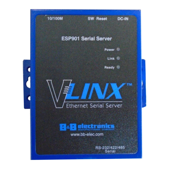
Making Hardware Connections Making Hardware Connections Indicator Lights Light Indication Red - power is applied Power Yellow – 10BaseT Ethernet connection established Link Green – 100BaseTX Ethernet connection established Package Checklist Flashing Green – system is ready Ready are shipped with the following ESP901 and ESP902 Serial Servers Figure 5. -
Page 10: Dip Switches
Mode, Default Mode Upgrade Mode With any DIP switch in the OFF position set the Server configured for RS-232, RS-422 or RS-485 operation. The server also Properties Console Mode field to Console and Update/Save the configuration can be put into... -
Page 11: Default Mode
ESP902 Serial Port 1. Since the computer is a DTE device, and the RS-485 Mode serial ports are configured as DTEs (with DB-9M connectors), a null the currently selected port is configured as an RS-485 modem crossover cable must be used. RS-485 Mode interface supporting transmit (TX) and receive (RX) signal channels using 2-wire, half-duplex operation. -
Page 12: Serial Server Serial Port Connectorp
Making Hardware Connections Making Hardware Connections Serial Server Serial Port Connector Pin-outs Pin-outs for RS-232, RS-422 and RS-485 operation are shown below. DB-9M RS-232 RS-422 RS-485 Signal Name Carrier Detect RXDA (−) Receive Data RXDB (+) Transmit Data TXDB (+) -
Page 13: Chapter 3: Installing The Vlinx Esp Software
Installing the VLINX ESP Software Installing the VLINX ESP Software Figure 13. The Install Shield Wizard Window The Windows-based software ESP Manager Virtual COM Port Step 2: When the window appears, click VLINX ESP Setup Next makes configuration fast and easy. If using Windows, installing the ESP Manager software and setting up virtual COM ports to configure is recommended. - Page 14 Installing the VLINX ESP Software Installing the VLINX ESP Software The recommended procedure is to Remove all installed components first. Once the software has been removed, the new software. Install Opening the ESP Manager Step 5: If the is not already connected to the network or Serial Server to the Ethernet port on the computer, connect it.
-
Page 15: Chapter 4: Using Esp Manager
Using ESP Manager Using ESP Manager software allows: ESP Manager • Searching for servers connected to the network • Displaying and changing the configuration of those servers • Installing virtual COM ports on a computer • Displaying and configuring virtual COM ports •... -
Page 16: Software Overview
Using ESP Manager Using ESP Manager • - Searches for on the network Searching Server Serial Servers and brings back configuration information that will be displayed in window. Server Properties • - Allows virtual COM ports to be Uninstall Virtual COM uninstalled from the window. -
Page 17: Status Bar
Using ESP Manager Using ESP Manager • - Displays the port number for each port. Exit Port Serial Server • Allows you to program Exit ESP Manager • - Indicates what type of flow control is configured Flow Control for each port. Help •... -
Page 18: Configure Server Properties
Using ESP Manager Using ESP Manager Enter the assigned to the desired Step 5: IP Address Serial Server click then Search all reachable servers, OK. IP Address used to find units that are not on the same Serial Server subnet. (Routers on the network will block the standard broadcast used to find servers if Search all reachable servers is selected.) The user must set an IP address that conforms to... - Page 19 Using ESP Manager Using ESP Manager Figure 26. The Restarting Dialogue Box After eight seconds a dialogue box will ask whether you want to search for all reachable servers again. Figure 27. The Server Search Dialogue Box While the Serial Server is searching for all reachable servers the following dialogue box appears: Figure 28.
-
Page 20: Description Of The Server Properties
Server Properties Configuration Server Properties Configuration Description of the Server Properties can be configured using any of four different VLINX Serial Server user interfaces: the software, ESP Manager Console Mode, Telnet . The described in this chapter can Web Server Server Properties be changed from any of these user interfaces. -
Page 21: Ip Address
Server Properties Configuration Server Properties Configuration address, net mask, and gateway to the . If a DHCP server Netmask Serial Server is not available on the network the will time out after 10 Serial Server The default LAN netmask is configured for a Class C address. The user seconds and the default values will remain. -
Page 22: Flow Control
This Select None when setting the port as RS-485 or 4-wire RS-422. field can be set to any value between 0 and 255 minutes. If zero, or no value, is entered into this field the server will not disconnect. -
Page 23: Port Status
• – When this mode is selected and the server updated, the Port Status RS-485 selected serial port will become an RS-485 serial port on the This field indicates whether a serial port is connected via the Serial server. to a virtual COM port of a device on the network. - Page 24 Server Properties Configuration Server Properties Configuration After that port has been updated you may want to re-enter Server to verify the changes have taken effect, or to view/change Properties the configuration of other ports. Each port must be configured separately. Saving Configuration Data in Console Mode or Telnet Saving (updating) server properties is done from the Configuration...
- Page 25 Server Properties Configuration Server Properties Configuration Web Server Interface • interface provides the same updating options as Web Server . These are located at the bottom of all Console Mode Telnet three pages. If a field is changed, you must click Web Server Save before leaving that page or the changes will be ignored.
-
Page 26: Virtual Com Port Installation
Installing Virtual COM Port Installing Virtual COM Port The program searches the LAN for all available . When Serial Servers complete, the window appears and displays a list of the Found Server servers that were found. feature allows Windows platform software, using Virtual COM Port standard API calls, to be used in an Ethernet application. -
Page 27: Matching The Serial Server And Virtual Com Port Settings
Installing Virtual COM Port Installing Virtual COM Port Matching the Serial Server and Virtual COM Port Settings The settings of the virtual COM ports in the and the Device Manager must match. If the settings do not Serial Server Configuration Menu match, the virtual COM ports will not work. - Page 28 Installing Virtual COM Port Installing Virtual COM Port Figure 43. The VLINX ESP (COM3) Properties Window Step 4: Click the tab. This screen Configuration Port Settings allows the settings to be changed if necessary. Click Cancel keep the existing settings. Step 5: Click to change the settings.
-
Page 29: Chapter 7: Removing Virtual Com Ports
Removing Virtual COM Ports Removing Virtual COM Ports Step 3: Click the icon. The Manager will ask Uninstall Virtual COM for conformation. Click to complete the uninstall procedure. software feature will ESP Manager Uninstall Virtual COM Port remove a mapped COM port in the Device Manager of Windows 2000 and XP operating systems. - Page 30 Removing Virtual COM Ports Removing Virtual COM Ports Figure 46. The Control Panel Window Figure 48. Confirm Device Removal Step 3: Click in the window. In Step 5: click to proceed. Device Manager Systems Properties the Device Manager dialogue click the next to Ports (COM to expand.
-
Page 31: Chapter 8: Upgrading The Serial Server Firmware
Upgrade Mode Upgrade Mode Step 4: Click on the dialogue to restart the vcomui Serial Server Upgrading the Firmware Step 5: Double-click the icon (or click the Firmware Upgrade Server menu and Firmware Upgrade Step 6: In the window, click . -
Page 32: Chapter 9: Using Console Mode
Using Console Mode Using Console Mode Navigating the Configuration Menus There are six screens: Console Mode Server Network Serial Mode Operation Monitor Configuration Back Space arrow keys can be used to highlight the desired function on the screen list. Pressing moves the cursor to the first field with the current Enter screen. -
Page 33: Using A Password
Using Console Mode Using Console Mode Step 5: Once all the changes have been made move to the screen, select and press Configuration Save Enter Figure 51. Saving and Restarting the Configuration The restart message will appear. Step 6: Select to save changes. -
Page 34: Chapter 10: Using The Web Server
Using the Web Server Using the Web Server Navigate and change properties as required using the mouse and keyboard. To change serial port properties, click on the left side of the Serial Port browser window. The following page will appear: The Web Server can be used to configure the from any Serial Server... - Page 35 Using the Web Server Using the Web Server Figure 54. The Web Server Operation Page Click to store changes to the . Settings for each Port Save Serial Server must be saved separately. If new property settings are not saved before leaving this page they will not take effect.
-
Page 36: Chapter 11: Using Telnet
Figure 55. The Run dialogue box The Serial Server must be in RS-232, RS-422 or RS-485 mode before you can Telnet to it and access the configuration screens. If it was last configured in Console mode you may not be able to access it using Telnet. In this case use ESP Manager, Console Mode or Web Server for configuration. - Page 37 Using Telnet Using Telnet Step 7: Once all the changes have been made move to the field Save and select . The restart message will appear. Enter Figure 57. Saving and Restarting the Configuration Step 8: Select to save changes. This is necessary to write the settings to the server.
- Page 38 RS-232(DTE): TXDB(+), TXDA(−), RXDB(+), RXDA(−), RS-422: RTS(+), RTS(−), CTS(+), CTS(−) and GND Data B (+), Data A (–) and GND RS-485: 110 bps to 230.4 k bps Baud Rate: Hardware and ESP901 and ESP902 Serial Server modules None, Even, Odd, Mark, Space...
- Page 39 ESP901 and ESP902 Technical Data ESP901 and ESP902 Technical Data ESP901 or ESP902 Default Server Server Name Settings xxxxxxxxx (printed on bottom of Serial Number: unit) Blank Password: Disable DHCP: 192.168.0.1 IP Address: 255.255.255.0 Net Mask: 192.168.0.254 Gateway: Fixed – see bottom label MAC Address: current firmware version number &...
-
Page 40: Appendix A: Rs-232 Connections
RS-232 Connections RS-232 Connections RS-232 Straight-through Cable Connections In the RS-232 mode, the ’s ports are configured as DTEs Serial Server like a computer. If the device connected to the Serial Server configured as a DCE use a straight through cable wired as shown below: Serial Server DB-9 Pin-outs in RS-232 Mode RS-232 Signal Names... -
Page 41: Rs-232 Straight-Through Db-9 To Db-25 Conversion Connections
RS-232 Connections RS-232 Connections RS-232 Straight-through DB-9 to DB-25 Conversion RS-232 DTE Loopback Connections Connections Figure 65. Loopback Connections for RS-232 For Transmit and Receive loopback, connect only those lines. Figure 63. DB-9 to DB-25 Straight-through Cable Connections When Flow Control setting on the is set for RTS/CTS, RS-232 Crossover DB-9 to DB-25 Conversion Connections Serial Server... -
Page 42: Serial Server Db-9 Pin-Outs In Rs-422 Mode
Ground is signal ground and provides a common mode reference for the RS-422 Receiver and Transmitters. The RS-422 mode can be used for full duplex 4-wire RS-485 operation provided that the serial server is acting as a sole master connecting to all the slave devices, and all slave devices share the Receive signal lines to the master. - Page 43 RS-422 Connections RS-422 Connections Figure 68. Loopback Connections for RS-422 The RS-485 Connections are half duplex, either Receive or Transmit, so another half duplex device must be used to check operation. Figure 69. RS-422 Connection with No Flow Control Manual Documentation Number: ESP901-902_4105m...
-
Page 44: Appendix C: Rs-485 Connections
Data B line as positive relative to Data A during a Mark state before enabling the transmitter, and after transmitting before tri-stating. If an RS-485 device does not respond, try swapping the Data B and Data A lines. -
Page 45: Appendix D: Network Connections
Network Connections Network Connections Crossover Ethernet Cable RJ-45 Pin-out Standard Ethernet Cable RJ-45 Pin-out RJ-45 Pin Signal Wire Color RJ-45 Pin White-Green Green White-Orange RJ-45 Pin Signal Wire Color RJ-45 Pin Not used Blue White-Green Not used White-Blue Green Orange White-Orange Not used White-Brown... - Page 46 International Headquarters B&B Electronics Mfg. Co. Inc. 707 Dayton Road Ottawa, IL 61350 USA Phone (815) 433-5100 -- General Fax (815) 433-5105 Website: www.bb-elec.com Sales e-mail: orders@bb-elec.com -- Fax (815) 433-5109 Technical Support e-mail: support@bb.elec.com -- Fax (815) 433-5104 European Headquarters B&B Electronics Ltd.
Need help?
Do you have a question about the RS-485 and is the answer not in the manual?
Questions and answers