
Related Manuals for B&B Electronics Vlinx VESP211


Summary of Contents for B&B Electronics Vlinx VESP211
- Page 2 Document Name: VESP211_R002_0613 Revision: 2.0 -- February 2013 This product designed and manufactured in Ottawa, Illinois USA using domestic and imported parts by International Headquarters B&B Electronics Mfg. Co. Inc. 707 Dayton Road Ottawa, IL 61350 USA Phone (815) 433-5100 -- General Fax (815) 433-5105 Website: www.bb-elec.com European Headquarters...
-
Page 3: Table Of Contents
Table of Contents Introduction ......................7 About VESP211 Serial Servers ................7 VESP211 Serial Server Model Numbering .............. 8 VESP211 Features ..................... 8 Vlinx Manager Configuration Software ..............8 VESP211 Hardware ....................9 Package Checklist ....................9 VESP211 Serial Server Enclosures and Mounting ........... 9 LED Indicators .................... - Page 4 Installing and Starting Vlinx Manager ..............20 Discovering Serial Servers ................. 20 Configuring the Serial Server ................23 Overview of the Vlinx Manager ................23 Icons ....................24 Serial Server Information Table .............. 24 Configuration Pane ................25 Logging In ....................... 25 Navigating the Configuration Pages ..............
- Page 5 Description of Serial Server Properties ..............49 Appendix ......................59 Appendix A: Default Server Settings ..............59 Appendix B: Product Specifications ..............60 General Specifications ................60 Controls, Indicators and Connector Specifications ........61 Serial Interface Specifications ..............61 Network Specifications ................62 TCP/UDP Ports Table ................
-
Page 7: Introduction
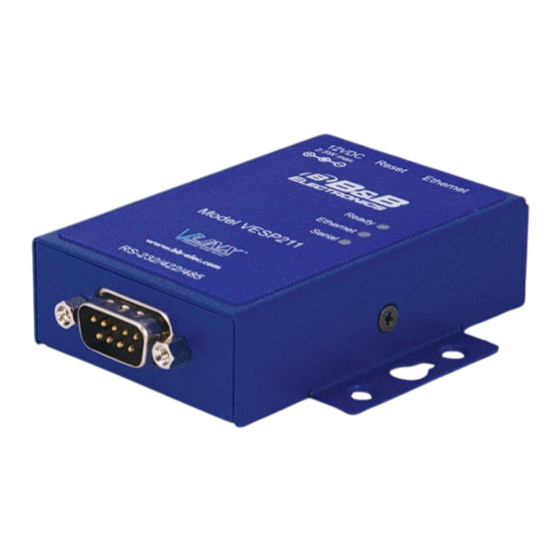
Section 1 - Introduction Vlinx VESR4x4 Serial Server ECTION Introduction Thank you for purchasing a VESP211 Serial Server product! This product has been manufactured to the highest standards of quality and performance to ensure your complete satisfaction. Figure 1. A VESP211 Serial Server About VESP211 Serial Servers VESP211 Serial Servers connect serial devices (RS-232, RS-422 or RS-485) to Ethernet networks, allowing the serial device to become a node on the... -
Page 8: Vesp211 Serial Server Model Numbering
Section 1 - Introduction Vlinx VESR4x4 Serial Server VESP211 Serial Server Model Numbering The VESP211 Serial Server family of products includes three models: VESP211-232, which uses a DB-9M connector and supports the RS-232 serial interface VESP211-485, which uses a pluggable, five-position terminal strip and supports the RS-485 serial interface ... -
Page 9: Vesp211 Hardware
Section 2 - VESP211 Hardware Vlinx VESR4x4 Serial Server ECTION VESP211 Hardware VESP211 Serial Servers are enclosed in a rugged panel mountable enclosure and feature: LED indicators Power, Ethernet and serial connectors A recessed Reset (mode) switch. Package Checklist VESP211 Serial Servers are shipped with the following items included: ... -
Page 10: Led Indicators
Section 2 - VESP211 Hardware Vlinx VESR4x4 Serial Server LED Indicators VESP211s have three LED indicators: a Ready LED, an Ethernet LED, and a Serial LED. Figure 3. Front Panel of the VESP211 Ready LED The Ready LED (green) blinks once per second if the system is operating correctly. -
Page 11: Reset Switch
Section 2 - VESP211 Hardware Vlinx VESR4x4 Serial Server Note: LEDs on the serial server are also used to indicate various Reset modes, as described in the following section. Reset Switch A recessed momentary Reset switch is located on the side of the enclosure. To activate the switch, insert a small plastic tool through the hole in the enclosure and press lightly. -
Page 12: Using The Reset Switch To Exit Console Mode
Section 2 - VESP211 Hardware Vlinx VESR4x4 Serial Server Using the Reset Switch to exit Console Mode Press and hold the Reset switch for two seconds, or remove power from the serial server, wait a few seconds, and turn the power on again. The LEDs go back to their normal states when the device resumes normal operation. -
Page 13: Power Connector
Section 2 - VESP211 Hardware Vlinx VESR4x4 Serial Server VESP211-485 serial servers use five-position removable terminal blocks for RS-422 and RS-485 connections. Figure 6. Five-Position Pluggable Terminal Blocks Note: Refer to Appendix D for connection pin-outs. Power Connector VESP211 serial servers use a barrel jack connector for power. The connector accepts a 2.1 millimeter plug and requires 12 VDC at 2.5 W maximum. -
Page 14: Mounting Hardware
Section 2 - VESP211 Hardware Vlinx VESR4x4 Serial Server Figure 8. Mounting Hardware VESP211 Serial Server modules can be panel mounted using the built-in mounting brackets. Figure 9. VESP211 Enclosure with Panel Mount Bracket An optional DIN rail mount adapter is available from B&B Electronics. Page 14 of 67 www.bb-elec.com/ www.bb-europe.com/... -
Page 15: Initial Setup And Connections
Section 3 - Initial Setup and Connections Vlinx VESR4x4 Serial Server ECTION Initial Setup and Connections This section describes how to setup and connect VESP211 Serial Servers. In this section devices to be connected to the serial server’s serial connection are simply referred to Note: as the “serial device”. -
Page 16: Connecting Vesp211 Serial Servers To A Network
Section 3 - Initial Setup and Connections Vlinx VESR4x4 Serial Server RS-485 The RS-485 interface supports 2-wire or 4-wire operation. When configured for 4-wire operation the connection supports two signal pairs: TDA (-), TDB (+), RDA (-), RDB (+) and GND. This makes full-duplex operation possible. -
Page 17: Vesp211 Serial Server Configuration Connections
Section 3 - Initial Setup and Connections Vlinx VESR4x4 Serial Server VESP211 Serial Server Configuration Connections VESP211 Serial Servers can be configured using several methods: Via the network using Vlinx Manager software Via the network using a web browser ... -
Page 18: Configuring Via The Serial Port Using Vlinx Manager (Console Mode)
Section 3 - Initial Setup and Connections Vlinx VESR4x4 Serial Server Note: For more information on how to use Vlinx Manager to configure your serial server, refer to Section 4: Configuring the Serial Server Configuring via the Serial Port using Vlinx Manager (Console Mode) Your serial server can be configured via the serial port using Vlinx Manager. - Page 19 Section 3 - Initial Setup and Connections Vlinx VESR4x4 Serial Server Figure 13. Direct IP and Virtual COM Port Connection In Virtual COM Port Mode a PC can communicate across the network to the serial server as if the serial ports on the serial server are the PC’s serial ports. When a virtual COM port is configured on the PC (using Vlinx Manager) a new COM port appears in the Device Manager.
-
Page 20: Installing And Starting Vlinx Manager
Section 3 - Initial Setup and Connections Vlinx VESR4x4 Serial Server Installing and Starting Vlinx Manager Vlinx Manager is a Windows-based application used to configure serial servers. Install it on your PC from the included CD. Installation should launch automatically when the CD is placed in the CD-ROM drive. If it does not automatically launch, click Start on the Windows Desktop and, at the Run command, type the drive letter and Vlinx Manager.exe. - Page 21 Section 3 - Initial Setup and Connections Vlinx VESR4x4 Serial Server Color Description Black A step in the discovery process. Dark Blue A device was not found. Dark Green A device was found. Dark Red An error occurred. If one or more devices are found, the discovery window closes automatically and the Configuration window appears.
-
Page 23: Configuring The Serial Server
Section 4 - Configuring the Serial Server Vlinx VESR4x4 Serial Server ECTION Configuring the Serial Server Overview of the Vlinx Manager The Vlinx Manager configuration window includes three areas: Icons Serial Server Information Table Configuration pane Figure 16. Vlinx Manager Configuration Window Note: The screen shots shown in this manual refer to the VESR901. -
Page 24: Icons
Section 4 - Configuring the Serial Server Vlinx VESR4x4 Serial Server Icons Figure 17. Configuration Window Icons - choose a previously saved configuration file. Open Cfg - save the current configuration to a file. Save Cfg - initiate another search for servers. Server Search ... -
Page 25: Configuration Pane
Section 4 - Configuring the Serial Server Vlinx VESR4x4 Serial Server When a serial server's IP address is configured for a network that is not within the local network's range, the serial server's information is displayed in a different color (orange). Configuration Pane The configuration pane is essentially a web browser. -
Page 26: Navigating The Configuration Pages
Section 4 - Configuring the Serial Server Vlinx VESR4x4 Serial Server Login 1. Double-click the row associated with the desired serial server. The page appears. 2. Type the password into the box. The password is blank by Password default. Figure 20. Login Page 3. -
Page 27: Changing The Serial Server's Name
Section 4 - Configuring the Serial Server Vlinx VESR4x4 Serial Server Figure 21. General Configuration Page Changing the serial server’s name: 1. Type the new name into the text box. Serial Server Name 2. Click Save Changing the password: Select the check box. -
Page 28: Setting Up Dynamic Ip Addressing
Section 4 - Configuring the Serial Server Vlinx VESR4x4 Serial Server Figure 23. Network Configuration Page Setting up Dynamic IP Addressing 1. Select the check box. I want to use DHCP to setup the network Setting up Static IP Addressing 1. -
Page 29: Setting Up Port Network Parameters
Section 4 - Configuring the Serial Server Vlinx VESR4x4 Serial Server Figure 25. Serial Port Configuration Page - select the type of serial connection (RS-232, RS-422, RS-485 2- Mode wire or RS-485 4-wire) required to connect the serial device to the serial server. -
Page 30: Tcp Configuration
Section 4 - Configuring the Serial Server Vlinx VESR4x4 Serial Server TCP Configuration provides reliable connection-oriented TCP (Transmission Control Protocol) network communication with error checking. In TCP mode the serial server can be configured as a client or a server. When you configure the serial server as a it initiates connections TCP client... -
Page 31: Udp Configuration
Section 4 - Configuring the Serial Server Vlinx VESR4x4 Serial Server 5. Select: - if you want the serial server to always be connected at power up - if you only want to establish a when the serial port receives data connection when there is data to be sent. - Page 32 Section 4 - Configuring the Serial Server Vlinx VESR4x4 Serial Server You can also configure the serial server to receive from nodes on the network using the same list of configuration options. Figure 28. UDP Configuration Setting the serial server to use UDP 1.
-
Page 33: Setting Up Virtual Com (Vcom) Operation
Section 4 - Configuring the Serial Server Vlinx VESR4x4 Serial Server If you selected: everyone on a specific UDP port (send broadcast) type the UDP port number into the This is the UDP port I want to send data to: ... -
Page 34: Setting Up Paired Mode Operation
Section 4 - Configuring the Serial Server Vlinx VESR4x4 Serial Server Figure 29. VCOM Configuration Note: Both the serial server and the computer must be configured for VCOM operation. To set up a virtual COM port on the computer, refer to the section on Adding Virtual COM Ports. - Page 35 Section 4 - Configuring the Serial Server Vlinx VESR4x4 Serial Server Figure 30. Paired Mode Configuration Setting the serial server to operate in Paired Mode as a client 1. Select protocol. Paired 2. Select to initiate connections (client) 3. Type the IP address and TCP port numbers of the server in the appropriate text boxes.
-
Page 36: Setting Up Advanced Network Settings
Section 4 - Configuring the Serial Server Vlinx VESR4x4 Serial Server 3. Type the TCP port number to be used in the I want to wait for connections box. on TCP port number 4. Select the number of connections in the and limit the number of drop down box. -
Page 37: Configuring When Connections Will Be Forced Closed
Section 4 - Configuring the Serial Server Vlinx VESR4x4 Serial Server Figure 34. Advanced Network Settings Window with nothing selected Configuring when connections will be forced closed 1. Select the I want to control when connections would be forced closed checkbox. -
Page 38: Configuring When Data Packets Are Sent
Section 4 - Configuring the Serial Server Vlinx VESR4x4 Serial Server 2. Type the desired time period (in milliseconds) into the text box. Configuring when data packets are sent 1. Select the I want to control when data packets are sent over the network checkbox. - Page 39 Section 4 - Configuring the Serial Server Vlinx VESR4x4 Serial Server To wait until a specific amount of data is received on the serial port before sending it across the network 1. Select: I want to wait for a specific amount of data to be received by the Character Count in the serial port before sending it...
- Page 40 Section 4 - Configuring the Serial Server Vlinx VESR4x4 Serial Server To force the serial server to remove the delimiter characters from the data when it sends it on its serial port 1. Select: I want to remove the delimiter characters from the data before sending the data.
-
Page 41: Saving/Restoring The Configuration Settings
Section 4 - Configuring the Serial Server Vlinx VESR4x4 Serial Server Saving/Restoring the Configuration Settings Save Configuration When all configuration windows are complete the page appears. Figure 37. Save Configuration Page To save the configuration to the serial server, and re-boot it so that the configuration settings will take effect 1. - Page 42 Section 4 - Configuring the Serial Server Vlinx VESR4x4 Serial Server Figure 38. Add Virtual COM Port Dialog Box Using the drop down boxes you can select the serial server you want to map the virtual COM port to, the number of the serial port on the serial server and the COM port on the local computer.
-
Page 43: Removing Virtual Com Ports
Section 4 - Configuring the Serial Server Vlinx VESR4x4 Serial Server Removing Virtual COM Ports Clicking the icon (located at the top of the Vlinx Manager Remove VCOM Remove Virtual COM Port Configuration window) opens the dialog box. Figure 39. Remove Virtual COM Port Dialog Box Using the drop down boxe you can select the virtual COM port on the local computer. -
Page 44: Upgrading The Serial Server Firmware
Section 4 - Upgrading the Serial Server Firmware Vlinx VESR4x4 Serial Server ECTION Upgrading the Serial Server Firmware Occasionally, updated firmware may become available for your serial server. The firmware can be upgraded using the Vlinx Manager software. The following procedure describes the firmware updating process: Firmware Upgrade 1. -
Page 45: To Download The Latest Firmware Files From An Ftp Site On The Internet
Section 4 - Upgrading the Serial Server Firmware Vlinx VESR4x4 Serial Server To download the latest firmware files from an FTP site on the Internet 1. Click the button at the bottom of the window. Internet The Vlinx Manager connects to an FTP server on the Internet. 2. -
Page 46: Diagnostics
Section 7 - Diagnostics Vlinx VESR4x4 Serial Server ECTION Diagnostics Diagnostics Clicking the icon opens the dialog box and enables you Diagnostic to check the operation of connected serial servers and VCOM ports on the local computer. box displays information about the type of network Computer Information connections, the IP addresses, Subnet Masks and Default Gateways in use. -
Page 47: Testing A Serial Server Connection
Section 7 - Diagnostics Vlinx VESR4x4 Serial Server Testing a Serial Server Connection 1. Click the icon. Diagnostic Diagnostics dialog box appears. 2. Select the option: a serial server 3. In the drop down box select the specific serial server you want to check. 4. -
Page 48: Testing A Virtual Com Port
Section 7 - Diagnostics Vlinx VESR4x4 Serial Server Testing a Virtual COM Port 1. Loopback the serial port (i.e. connect TD to RD) 2. Click the icon. Diagnostics Diagnostics dialog box appears. 3. Select the option: a virtual communications port 4. -
Page 49: Description Of Serial Server Properties
Section 8 - Description of Serial Server Properties Vlinx VESR4x4 Serial Server ECTION Description of Serial Server Properties The following serial server properties are ordered alphabetically to assist you in finding the information you need. Baud Rate is the communication speed of the link between the serial server and the device attached to its serial port. - Page 50 Section 8 - Description of Serial Server Properties Vlinx VESR4x4 Serial Server Delimiter 1, Delimiter 2 and Delimiter Removal Delimiters and Delimiter Removal enable you to control how characters received on a serial port are sent across the network. Delimiters are ASCII characters specified by the user when configuring the serial server.
- Page 51 Section 8 - Description of Serial Server Properties Vlinx VESR4x4 Serial Server This product is factory defaulted to the DHCP mode. It is intended that your network’s DHCP Server Note 1: provide the IP address assignment. If there is not a DHCP server on your network, the device will default to IP address 169.254.102.39.
- Page 52 Section 8 - Description of Serial Server Properties Vlinx VESR4x4 Serial Server 1. Method One: Change your PC Network to Match the Serial Server Open the network connection on your PC Figure 44. Network IP Properties Click and then click .
- Page 53 Section 8 - Description of Serial Server Properties Vlinx VESR4x4 Serial Server Enter Console Mode. Press and hold the serial server’s reset switch for 2 to 10 seconds. The LED indicators will respond as follows: Model Port 1 LED Port 2 LED Ready LED 1 Port 2 Port...
- Page 54 Section 8 - Description of Serial Server Properties Vlinx VESR4x4 Serial Server The MAC Address is a hardware level address of the serial server that cannot be changed. It is assigned in the factory. Every Ethernet device manufactured has its own unique MAC address. The MAC address of each serial server is printed on the device's label.
- Page 55 Section 8 - Description of Serial Server Properties Vlinx VESR4x4 Serial Server kbaud over short distances (typically 50 feet). Typically uses DB-9 connectors but terminals are also used on VESP211 serial servers. RS-422 - Point-to-point communications using a transmit pair and a receive pair.
- Page 56 Section 8 - Description of Serial Server Properties Vlinx VESR4x4 Serial Server For a Class D network (IP addresses 224.0.0.0 through 239.255.255.255) and Class E Networks (IP addresses 240.0.0.0 through 255.255.255.255) the subnet mask is ignored. VESP211serial servers come from the factory with a default subnet mask value of: 255.255.255.0 TCP (Transmission Control Protocol) provides reliable connection-oriented network communication with error checking.
- Page 57 Section 8 - Description of Serial Server Properties Vlinx VESR4x4 Serial Server Both the serial server and the computer must be configured for VCOM operation. Virtual COM ports can be set up on the PC using the Vlinx Manager software. Page 57 of 67 www.bb-elec.com/ www.bb-europe.com/...
-
Page 59: Appendix
Section 9 - Appendix Vlinx VESP211 Serial Server ECTION Appendix Appendix A: Default Server Settings Setting Default Value Server Name MODEL NUMBER Serial Number Printed on the label Password password field is blank from factory DHCP Enable IP Address BASED ON DHCP SERVER If a DHCP assignment is not available, the device will default to 169.254.102.39... -
Page 60: Appendix B: Product Specifications
Section 9 - Appendix Vlinx VESP211 Serial Server Appendix B: Product Specifications General Specifications Hardware and Device Serial Server included accessories CD with Vlinx Manager software for XP (32/64 bit), 2003 Server (32/64 bit), Vista (32/64 bit), 2008 Server (32/64 bit),... -
Page 61: Controls, Indicators And Connector Specifications
Section 9 - Appendix Vlinx VESP211 Serial Server Controls, Indicators and Connector Specifications Switches Reset button Hold in for 0 to 2 seconds for hardware reset Hold in for 2 to 10 seconds for Console Mode (Do a hardware reset... -
Page 62: Network Specifications
Section 9 - Appendix Vlinx VESP211 Serial Server Network Specifications Memory Serial Memory 8 KB per port Network Memory 4 KB I/P Port Addresses 5300 Heartbeat & Configuration setting in TCP Mode (i.e. Pair Mode) 8888 VESP211 update Network 10/100 Mbps Auto-detecting 10BaseT or 100BaseTX... -
Page 63: Tcp/Udp Ports Table
Section 9 - Appendix Vlinx VESP211 Serial Server TCP/UDP Ports Table Port Description Comments 80/tcp Always open for the web server. This port is used for configuration of the device using a web browser. This port is always open no matter how you configure the device. - Page 64 Section 9 - Appendix Vlinx VESP211 Serial Server 8899/udp Always open for serial server discovery. This port is used for discovering serial servers. This port is always open no matter how you configure the device. Note: The device discovery only works on a local subnet. The port may not need to be configured in a firewall or NAT.
-
Page 65: Appendix C: Dimensional Diagram
Section 9 - Appendix Vlinx VESP211 Serial Server Appendix C: Dimensional Diagram Figure 46. Dimensional Diagram of a VESP211 Serial Server (dimensions in inches & millimeters) Page 65 of 67 www.bb-elec.com/ www.bb-europe.com/... -
Page 66: Appendix D: Connector Pinouts
Section 9 - Appendix Vlinx VESP211 Serial Server Appendix D: Connector Pinouts DB-9M Connnector DB-9M Pin RS-232 Direction (RS-232) RS-422/485 4-Wire RS-485 2-Wire Input RDA (-) Input RDB (+) Output TDB (+) Data B (+) Output TDA (-) Data A (-) -
Page 67: Standard Ethernet Cable Rj-45 Pin-Out
Section 9 - Appendix Vlinx VESP211 Serial Server Note 1: In the RS-422 mode, TX lines are outputs and RX lines are inputs. Connect the serial server TDB(+) line to the RDB(+) line of the serial device, and the serial server TDA(-) to the RDA(-) of the serial device.
Need help?
Do you have a question about the Vlinx VESP211 and is the answer not in the manual?
Questions and answers