
Related Manuals for B&B Electronics Vlinx VESR4 4 Series


Summary of Contents for B&B Electronics Vlinx VESR4 4 Series
- Page 1 User Manual...
- Page 2 Vlinx Serial Servers Documentation Number: VESR4x4_R001_0413m This product designed and manufactured in Ottawa, Illinois USA using domestic and imported parts by International Headquarters: 707 Dayton Road - P.O. Box 1040 - Ottawa, IL 61350 USA Phone (815) 433-5100 - General Fax (815) 433-5105 Website: www.bb-elec.com European Headquarters: B&B Electronics...
-
Page 3: Table Of Contents
Table of Contents Introduction ......................7 About VESR4x4 Serial Servers ................7 VESR4x4 Serial Server Model Numbering .............. 8 List of VESR4x4 Serial Server Models ..............8 VESR4x4 Features ..................... 9 Vlinx Manager Configuration Software ..............9 VESR4x4 Hardware....................11 Package Checklist ..................... - Page 4 Ethernet Pass-through Port ................21 VESR4x4 Serial Server Configuration ..............23 Configuring via the Network using Vlinx Manager ........23 Configuring via the network using a Browser ..........23 Configuring via a Serial Port using Vlinx Manager (Console Mode) ....24 VESR4x4 Serial Server Operational Connections ...........
- Page 5 Uploading the Firmware to the Serial Server ............50 Diagnostics ......................51 Testing a Serial Server Connection ..............51 Testing a Virtual COM Port ................. 52 Listing/Descriptions of Serial Server Settings ............54 Appendix ......................63 Appendix A: Default Server Settings ..............63 Appendix B: Product Specifications ..............
- Page 6 Page 6 of 70 www.bb-elec.com/ www.bb-europe.com/...
-
Page 7: Introduction
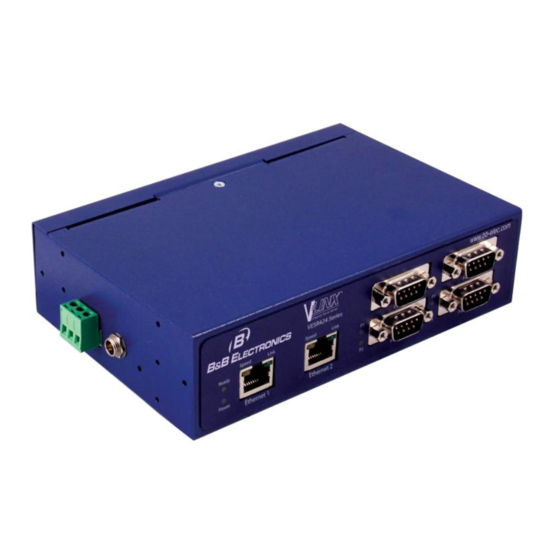
Section 1 - Introduction Vlinx VESR4x4 Serial Server ECTION Introduction Thank you for purchasing a VESR4x4 Serial Server product! This product has been manufactured to the highest standards of quality and performance to ensure your complete satisfaction. Figure 1. A VESR4x4 Serial Server About VESR4x4 Serial Servers VESR4x4 Serial Servers connect serial devices (RS-232, RS-422 or RS-485) to Ethernet networks, allowing the serial device to become a node on the... -
Page 8: Vesr4X4 Serial Server Model Numbering
Section 1 - Introduction Vlinx VESR4x4 Serial Server VESR4x4 Serial Server Model Numbering VESR4x4 Serial Servers are a growing family of products. All models incorporate four serial connections and, depending on the model, may have one or two Ethernet connections with an optional fiberoptic connection. The following diagram shows the model numbering scheme: List of VESR4x4 Serial Server Models The following table lists the various VESR4x4 models available. -
Page 9: Vesr4X4 Features
Section 1 - Introduction Vlinx VESR4x4 Serial Server VESR4x4 Features VESR414x series models – single Ethernet connector VESR424x-xx series models – two Ethernet connectors Ethernet Fiber port models available Ethernet pass through ports (on two Ethernet port models) ... -
Page 11: Vesr4X4 Hardware
Section 2 - VESR4x4 Hardware Vlinx VESR4x4 Serial Server ECTION VESR4x4 Hardware VESR4x4 Serial Servers are enclosed in rugged DIN rail or panel mountable enclosures and feature: LED indicators Power, Ethernet and serial connectors A recessed Reset (mode) switch. Package Checklist VESR4x4 Serial Servers are shipped with the following items included: ... -
Page 12: Power Led
Section 2 - VESR4x4 Hardware Vlinx VESR4x4 Serial Server Figure 3. Front Panel of the VESR424D Power LED The Power LED illuminates when 10 to 58 VDC power is applied to either power connector. Ready LED The Ready LED (green) illuminates continuously while the unit is initializing. It flashes once per second when the system is operating correctly. -
Page 13: Reset Switch
Section 2 - VESR4x4 Hardware Vlinx VESR4x4 Serial Server Note: LEDs on the serial server are also used to indicate various Reset modes, as described in the following section. Reset Switch A recessed momentary Reset switch is located on the side of the enclosure. To activate the switch, insert a small plastic tool through the hole in the enclosure and press lightly. -
Page 14: Using The Reset Switch To Reload Factory Default Settings
Section 2 - VESR4x4 Hardware Vlinx VESR4x4 Serial Server Using the Reset Switch to Reload Factory Default Settings Hold the Reset switch for more than ten seconds. The P1 LED illuminates for the first two seconds; then the P2 LED illuminates. After 10 seconds the P1 and P2 LEDs will illuminate. -
Page 15: Serial Port Connectors
Section 2 - VESR4x4 Hardware Vlinx VESR4x4 Serial Server Serial Port Connectors VESR4x4 Serial Servers feature two serial port connector configurations, depending on the model: VESR4x4D-x serial servers feature four serial ports, all of which use DB- 9M connectors for RS-232, RS-422 and RS-485 connections. ... -
Page 16: Mounting Hardware
Section 2 - VESR4x4 Hardware Vlinx VESR4x4 Serial Server Figure 9. Power Connectors Mounting Hardware VESR4x4 Serial Servers can be DIN rail or panel mounted. The necessary hardware is included in the accessory kit, which also includes the screws for attaching the mounting hardware. - Page 17 Section 2 - VESR4x4 Hardware Vlinx VESR4x4 Serial Server Figure 12. VESR424 with DIN Rail Clip Mounted Page 17 of 70 www.bb-elec.com/ www.bb-europe.com/...
-
Page 19: Installation And Initial Setup
Section 3 - Installation and Initial Setup Vlinx VESR4x4 Serial Server ECTION Installation and Initial Setup This section describes how to install the VESR4x4 Serial Server and configure the device. In this section devices to be connected to the serial server’s serial connections are simply referred Note: to as the “serial device”. - Page 20 Section 3 - Installation and Initial Setup Vlinx VESR4x4 Serial Server Signals single-ended referenced Signal Ground. Default communications parameters are 9600, 8, N, 1 (9600 baud, 8 data bits, no parity, 1 stop bit), and no flow control. Note: The VESR4x4 is configured as a DTE. If it is connected to a computer or other DTE device, use a null modem (cross-over) cable.
-
Page 21: Connecting Vesr4X4 Serial Servers To A Network
Section 3 - Installation and Initial Setup Vlinx VESR4x4 Serial Server Note: Refer to Appendix D for connector pinout information. Figure 14. VESR4x4 Connections Connecting VESR4x4 Serial Servers to a Network Ethernet Connection (10BaseT/100BaseTX) When connecting a serial server equipped with a 10BaseT/100BaseTX network connection (RJ45 connector) to an Ethernet network, a standard unshielded twisted-pair cable can be used. - Page 22 Section 3 - Installation and Initial Setup Vlinx VESR4x4 Serial Server Figure 15. Ethernet Pass-through Port Page 22 of 70 www.bb-elec.com/ www.bb-europe.com/...
-
Page 23: Vesr4X4 Serial Server Configuration
Section 3 - Installation and Initial Setup Vlinx VESR4x4 Serial Server VESR4x4 Serial Server Configuration VESR4x4 Serial Servers can be configured using several methods: Via the network using Vlinx Manager Software Via the network using a web browser ... -
Page 24: Configuring Via A Serial Port Using Vlinx Manager (Console Mode)
Section 3 - Installation and Initial Setup Vlinx VESR4x4 Serial Server Note: For more information on how to use Vlinx Manager to configure your serial server, refer to Section 4: Configuring the Serial Server Configuring via a Serial Port using Vlinx Manager (Console Mode) Your serial server can be configured via any serial port, using Vlinx Manager. - Page 25 Section 3 - Installation and Initial Setup Vlinx VESR4x4 Serial Server Figure 18. Direct IP and Virtual COM Port Connection In Virtual COM Port Mode the serial ports on the serial server appear to applications running on the host PC as if the serial ports were physically located on the host PC.
-
Page 26: Installing And Starting Vlinx Manager
Section 3 - Installation and Initial Setup Vlinx VESR4x4 Serial Server Figure 19. Paired Mode Setup Installing and Starting Vlinx Manager Vlinx Manager is a Windows-based application used to configure serial servers. Install it on your PC from the included CD. Installation should launch automatically when the CD is placed in the CD-ROM drive. -
Page 27: Discovering Serial Servers
Section 3 - Installation and Initial Setup Vlinx VESR4x4 Serial Server Progress Box Progress Bar Figure 20. Discovery Window Discovering Serial Servers If you are configuring the serial server via the network, select ; if you Network are configuring it via the serial port, select Serial Port If you already know the IP address of the serial server, click The device is at... -
Page 28: Configuring The Serial Server
Section 4 - Configuring the Serial Server Vlinx VESR4x4 Serial Server ECTION Configuring the Serial Server Overview of the Vlinx Manager The Vlinx Manager configuration window includes three areas: Icons Serial Server Information Table Configuration pane Figure 21. Vlinx Manager Configuration Window Note: The screen shots shown in this manual refer to the VESR901. -
Page 29: Icons
Section 4 - Configuring the Serial Server Vlinx VESR4x4 Serial Server Icons Figure 22. Configuration Window Icons - Open a serial server configuration file. Open - Save the current serial server configuration to a file. Save - Initiate a search for serial servers. Search ... -
Page 30: Configuration Pane
Section 4 - Configuring the Serial Server Vlinx VESR4x4 Serial Server The status of whether the serial server is in use is updated periodically. When a serial server's IP address is configured for a network that is not within the local network's range, the serial server's information is displayed in a different color (yellow) Configuration Pane The configuration pane is essentially a web browser. -
Page 31: Logging In
Section 4 - Configuring the Serial Server Vlinx VESR4x4 Serial Server Logging In You can log in to any serial server listed in the Server Information Table. To log in: 1. Select the row associated with the desired serial server. The Login page appears. -
Page 32: Setting Up The Serial Server Name And Password
Section 4 - Configuring the Serial Server Vlinx VESR4x4 Serial Server Setting up the Serial Server Name and Password On the General Configuration page you can do the following: Change the name of the serial server Initiate a login password change Figure 26. -
Page 33: Setting Up Ip Addressing
Section 4 - Configuring the Serial Server Vlinx VESR4x4 Serial Server 3. Click Save Setting up IP Addressing Network Configuration On the page you can configure the serial server to use dynamic (DHCP) or static IP addressing on the network. Figure 28. -
Page 34: Setting Up Serial Ports
Section 4 - Configuring the Serial Server Vlinx VESR4x4 Serial Server Setting up Serial Ports On the Serial Port Configuration page you can configure the communications parameters of the current serial port. Parameters include the port mode, baud rate, data bits, parity, stop bits and type of flow control. Figure 30. -
Page 35: Tcp Configuration
Section 4 - Configuring the Serial Server Vlinx VESR4x4 Serial Server TCP Configuration provides reliable connection-oriented TCP (Transmission Control Protocol) network communication with error checking. In TCP mode the serial server can be configured as a client or a server. When you configure the serial server as a it initiates a connection TCP client... -
Page 36: Udp Configuration
Section 4 - Configuring the Serial Server Vlinx VESR4x4 Serial Server 4. Type the TCP port number of the server into the on TCP port number: box. 5. Select: - if you want the serial server to always be connected at power up ... - Page 37 Section 4 - Configuring the Serial Server Vlinx VESR4x4 Serial Server You can also configure the serial server to receive from nodes on the network using a similar list of configuration options. Figure 33. UDP Configuration Setting the serial server to use UDP 1.
-
Page 38: Setting Up Virtual Com (Vcom) Operation
Section 4 - Configuring the Serial Server Vlinx VESR4x4 Serial Server If you selected: everyone on a specific UDP port (send broadcast) type the UDP port number into the This is the UDP port I want to send data to: ... -
Page 39: Setting Up Paired Mode Operation
Section 4 - Configuring the Serial Server Vlinx VESR4x4 Serial Server Figure 34. VCOM Configuration Note: Both the serial server and the computer must be configured for VCOM operation. To set up a virtual COM port on the computer, refer to the section on Adding Virtual COM Ports (see page 47). - Page 40 Section 4 - Configuring the Serial Server Vlinx VESR4x4 Serial Server Figure 35. Paired Mode Configuration Setting the serial server to operate in Paired Mode as a client 1. Select protocol. Paired 2. Select to initiate connections (client) 3. Type the IP address and TCP port numbers of the server in the appropriate text boxes.
-
Page 41: Setting Up Advanced Network Settings
Section 4 - Configuring the Serial Server Vlinx VESR4x4 Serial Server 3. Type the TCP port number to be used in the I want to wait for connections box. on TCP port number 4. Select the number of connections in the and limit the number of drop down box. -
Page 42: Configuring When Network Connections Will Be Forced Closed
Section 4 - Configuring the Serial Server Vlinx VESR4x4 Serial Server Data that is received by the serial port is normally buffered for a short period of time and then forwarded over the Ethernet to the remote device. The VESR4x4 automatically optimizes the data buffering to reduce the network overhead and minimize the data transmission latency. -
Page 43: Configuring When Data Packets Are Sent
Section 4 - Configuring the Serial Server Vlinx VESR4x4 Serial Server Figure 40. Advanced Configuration - Forcing Connections Closed To close a network connection if no data is received from the network for a period of time 1. Select the I want to close a connection when data is not received on that checkbox connection for a period of time... - Page 44 Section 4 - Configuring the Serial Server Vlinx VESR4x4 Serial Server Figure 41. Advanced Configuration - Configuring when data packets are sent To wait until a specific amount of data is received on the serial port before sending it across the network 1.
- Page 45 Section 4 - Configuring the Serial Server Vlinx VESR4x4 Serial Server 2. Type the desired time period (in milliseconds) into the text box. To force the serial server to send buffered data if another character is not received within a certain period of time 1.
-
Page 46: Saving/Restoring The Configuration Settings
Section 4 - Configuring the Serial Server Vlinx VESR4x4 Serial Server Saving/Restoring the Configuration Settings Save Configuration When all configuration windows are complete the page appears. Figure 42. Save Configuration Page To save the configuration to the serial server, and re-boot it so that the configuration settings will take effect 1. -
Page 47: Adding Virtual Com Ports
Section 4 - Configuring the Serial Server Vlinx VESR4x4 Serial Server Adding Virtual COM Ports Clicking the icon (located at the top of the Vlinx Manager Configuration Add Virtual COM Port window) opens the dialog box. Figure 43. Add Virtual COM Port Dialog Box Using the drop down boxes you can select the serial server you want to map the virtual COM port to, the number of the serial port on the serial server and the COM port on the local computer. -
Page 48: Removing Virtual Com Ports
Section 4 - Configuring the Serial Server Vlinx VESR4x4 Serial Server Removing Virtual COM Ports Clicking the icon (located at the top of the Vlinx Manager Remove Remove Virtual COM Port Configuration window) opens the dialog box. Figure 44. Remove Virtual COM Port Dialog Box Using the drop down box you can select the virtual COM port on the local computer. -
Page 49: Upgrading The Serial Server Firmware
Section 5 - Upgrading the Serial Server Firmware Vlinx VESR4x4 Serial Server ECTION Upgrading the Serial Server Firmware Occasionally, updated firmware may become available for your serial server. The firmware can be upgraded using the Vlinx Manager Software. The following procedure describes the firmware updating process: Firmware Upgrade 1. -
Page 50: To Download The Latest Firmware Files From An Ftp Site On The Internet
Section 5 - Upgrading the Serial Server Firmware Vlinx VESR4x4 Serial Server To download the latest firmware files from an FTP site on the Internet 1. Click the button at the bottom of the window. Internet The Vlinx Manager connects to an FTP server on the Internet. 2. -
Page 51: Diagnostics
Section 6 - Diagnostics Vlinx VESR4x4 Serial Server ECTION Diagnostics Diagnostics Clicking the icon opens the dialog box and enables Diagnostics you to check the operation of connected serial servers and VCOM ports on the local computer. box displays information about the type of network Computer Information connections, the IP addresses, Subnet Masks and Default Gateways in use. -
Page 52: Testing A Virtual Com Port
Section 6 - Diagnostics Vlinx VESR4x4 Serial Server Figure 47. Testing a Serial Server Connection Testing a Virtual COM Port 1. Click the icon. Diagnostics Diagnostics dialog box appears. 2. Select the option: a virtual communications port 3. In the drop down box select the specific COM port you want to check. 4. - Page 53 Section 6 - Diagnostics Vlinx VESR4x4 Serial Server Figure 48. Testing a VCOM Port Page 53 of 70 www.bb-elec.com/ www.bb-europe.com/...
-
Page 54: Listing/Descriptions Of Serial Server Settings
Section 7 - Listing/Descriptions of Serial Server Settings Vlinx VESR4x4 Serial Server ECTION Listing/Descriptions of Serial Server Settings The following serial server properties are ordered alphabetically to assist you in finding the information you need. Baud Rate is the communication speed of the link between the serial server and the device attached to its serial port. - Page 55 Section 7 - Listing/Descriptions of Serial Server Settings Vlinx VESR4x4 Serial Server sent across the network. Delimiters are ASCII characters specified by the user when configuring the serial server. The serial server takes action when it recognizes the specified character(s) on its serial port. ...
- Page 56 Section 7 - Listing/Descriptions of Serial Server Settings Vlinx VESR4x4 Serial Server This product is factory defaulted to the DHCP mode. It is intended that your network’s DHCP Server Note 1: provide the IP address assignment. If there is not a DHCP server on your network, the device will default to IP address 169.254.102.39.
- Page 57 Section 7 - Listing/Descriptions of Serial Server Settings Vlinx VESR4x4 Serial Server 1. Method One: Change your PC Network to Match the Serial Server Open the network connection on your PC Figure 49. Network IP Properties Click and then click .
- Page 58 Section 7 - Listing/Descriptions of Serial Server Settings Vlinx VESR4x4 Serial Server Enter Console Mode. Press and hold the serial server‟s reset switch for 2 to 10 seconds. The LED indicators will respond as follows: Model Port 1 LED Port 2 LED Port 3 LED Port 4 LED Ready LED...
- Page 59 Section 7 - Listing/Descriptions of Serial Server Settings Vlinx VESR4x4 Serial Server The MAC Address is a hardware level address of the serial server that cannot be changed. It is assigned in the factory. Every Ethernet device manufactured has its own unique MAC address. The MAC address of each serial server is printed on the device's label.
- Page 60 Section 7 - Listing/Descriptions of Serial Server Settings Vlinx VESR4x4 Serial Server kbaud over short distances (typically 50 feet). Typically uses DB-9 connectors but terminals are also used on VESR4x4 serial servers. RS-422 - Point-to-point communications using a transmit pair and a receive pair.
- Page 61 Section 7 - Listing/Descriptions of Serial Server Settings Vlinx VESR4x4 Serial Server For a Class D network (IP addresses 224.0.0.0 through 239.255.255.255) and Class E Networks (IP addresses 240.0.0.0 through 255.255.255.255) the subnet mask is ignored. VESR4x4serial servers come from the factory with a default subnet mask value of: 255.255.255.0 TCP (Transmission Control Protocol) provides reliable connection-oriented network communication with error checking.
- Page 62 Section 7 - Listing/Descriptions of Serial Server Settings Vlinx VESR4x4 Serial Server Both the serial server and the computer must be configured for VCOM operation. Virtual COM ports can be set up on the PC using the Vlinx Manager software. Page 62 of 70 www.bb-elec.com/ www.bb-europe.com/...
-
Page 63: Appendix
Section 8 - Appendix Vlinx VESR4x4 Serial Server ECTION Appendix Appendix A: Default Server Settings Setting Default Value Server Name MODEL NUMBER Serial Number printed on side of unit Password password field is blank from factory DHCP Enable BASED ON DHCP SERVER IP Address If a DHCP assignment is not available, the device will default to 169.254.102.39 Net Mask... -
Page 64: Appendix B: Product Specifications
Section 8 - Appendix Vlinx VESR4x4 Serial Server Appendix B: Product Specifications General Specifications Hardware and Device Serial Server included accessories CD with Vlinx Manager Software for Windows 2000, XP (32/64 bit), 2003 Server (32/64 bit), Vista (32/64 bit), 2008 Server (32/64 bit), Windows 7 (32/64 bit) Optional Accessories Cable... -
Page 65: Controls, Indicators And Connector Specifications
Section 8 - Appendix Vlinx VESR4x4 Serial Server Controls, Indicators and Connector Specifications Switches Reset button Hold in for 0 to 2 seconds for hardware reset Hold in for 2 to 10 seconds for Console Mode (Do a hardware reset or recycle power to exit Console Mode) Hold in for more than 10 seconds to reset to factory defaults Indicators... -
Page 66: Network Specifications
Section 8 - Appendix Vlinx VESR4x4 Serial Server Network Specifications Memory Serial Memory 8 KB per port Network Memory 4 KB I/P Port Addresses 5300 Heartbeat & Configuration setting in TCP Mode (i.e. Pair Mode) 8888 VESR4x4 update Network 10/100 Mbps Auto-detecting 10BaseT or 100BaseTX Communications Network Physical Ethernet... - Page 67 Section 8 - Appendix Vlinx VESR4x4 Serial Server 60000/tcp This port is open when serial port 1 is These ports are used to transfer handshake line state and break state in configured for paired-mode server. paired mode configuration. These ports are open only if you configure the port for paired-mode server.
-
Page 68: Appendix C: Dimensional Diagrams
Section 8 - Appendix Vlinx VESR4x4 Serial Server Appendix C: Dimensional Diagrams Figure 51. Dimensional Diagram of a VESR424 Serial Server (dimensions in inches & millimeters) Page 68 of 70 www.bb-elec.com/ www.bb-europe.com/... -
Page 69: Appendix D: Connector Pinouts
Section 8 - Appendix Vlinx VESR4x4 Serial Server Appendix D: Connector Pinouts DB-9M Connnector DB-9M Pin RS-232 Direction (RS-232) RS-422/485 4-Wire RS-485 2-Wire Input RDA (-) Input RDB (+) Output TDB (+) Data B (+) Output TDA (-) Data A (-) Input Output Input... -
Page 70: Standard Ethernet Cable Rj-45 Pinout
Section 8 - Appendix Vlinx VESR4x4 Serial Server Note 1: In the RS-422 mode, TX lines are outputs and RX lines are inputs. Connect the serial server TXB(+) line to the RXB(+) line of the serial device, and the serial server TXA(-) to the RXA(-) of the serial device.
Need help?
Do you have a question about the Vlinx VESR4 4 Series and is the answer not in the manual?
Questions and answers