Table of Contents
Advertisement
Quick Links
R
S
R
E
t
h
e
E
t
h
e
M
o
d
e
M
o
d
e
B&B Electronics Mfg Co Inc – 707 Dayton Rd - PO Box 1040 - Ottawa IL 61350 - Ph 815-433-5100 - Fax 815-433-5104 – www.bb-elec.com
B&B Electronics Ltd – Westlink Commercial Pk – Oranmore, Galway, Ireland – Ph +353 91-792444 – Fax +353 91-792445 – www.bb-europe.com
-
2
3
2
/
R
S
-
2
3
2
/
R
M
u
l
t
i
-
M
u
l
t
i
r
n
e
t
S
r
n
e
t
l
s
:
E
S
P
9
0
1
,
E
l
s
:
E
S
P
9
0
1
,
E
Manual Documentation Number: ESP901-902_5012m
S
-
4
2
2
/
S
-
4
2
2
/
I
n
t
e
r
f
-
I
n
t
e
r
f
e
r
i
a
l
S
e
r
i
a
l
S
P
9
0
1
E
,
E
S
S
P
9
0
1
E
,
E
S
R
S
-
4
8
5
R
S
-
4
8
5
a
c
e
a
c
e
S
e
r
v
e
S
e
r
v
e
P
9
0
2
,
E
S
P
9
0
P
9
0
2
,
E
S
P
9
0
r
s
r
s
2
E
2
E
Advertisement
Table of Contents

Related Manuals for B&B Electronics ESP901


Summary of Contents for B&B Electronics ESP901
- Page 1 Manual Documentation Number: ESP901-902_5012m B&B Electronics Mfg Co Inc – 707 Dayton Rd - PO Box 1040 - Ottawa IL 61350 - Ph 815-433-5100 - Fax 815-433-5104 – www.bb-elec.com B&B Electronics Ltd – Westlink Commercial Pk – Oranmore, Galway, Ireland – Ph +353 91-792444 – Fax +353 91-792445 – www.bb-europe.com...
- Page 2 International Headquarters B&B Electronics Mfg. Co. Inc. 707 Dayton Road Ottawa, IL 61350 USA Phone (815) 433-5100 -- General Fax (815) 433-5105 Website: www.bb-elec.com Sales e-mail: orders@bb-elec.com -- Fax (815) 433-5109 Technical Support e-mail: support@bb.elec.com -- Fax (815) 433-5104 European Headquarters B&B Electronics Ltd.
- Page 3 Manual Documentation Number: ESP901-902_5012m B&B Electronics Mfg Co Inc – 707 Dayton Rd - PO Box 1040 - Ottawa IL 61350 - Ph 815-433-5100 - Fax 815-433-5104 – www.bb-elec.com...
- Page 4 Manual Documentation Number: ESP901-902_5012m B&B Electronics Mfg Co Inc – 707 Dayton Rd - PO Box 1040 - Ottawa IL 61350 - Ph 815-433-5100 - Fax 815-433-5104 – www.bb-elec.com B&B Electronics Ltd – Westlink Commercial Park – Oranmore, Galway, Ireland – Ph +353 91-792444 – Fax +353 91-792445 – www.bb-europe.co...
-
Page 5: Table Of Contents
Updating an Existing Installation .............. 19 Opening the ESP Manager ................ 20 Manual Documentation Number: ESP901-902_5012m Table of Contents B&B Electronics Mfg Co Inc – 707 Dayton Rd - PO Box 1040 - Ottawa IL 61350 - Ph 815-433-5100 - Fax 815-433-5104 – www.bb-elec.com... - Page 6 ETTINGS Table of Contents Manual Documentation Number: ESP901-902_5012m B&B Electronics Mfg Co Inc – 707 Dayton Rd - PO Box 1040 - Ottawa IL 61350 - Ph 815-433-5100 - Fax 815-433-5104 – www.bb-elec.com B&B Electronics Ltd – Westlink Commercial Pk – Oranmore, Galway, Ireland – Ph +353 91-792444 – Fax +353 91-792445 – www.bb-europe.com...
- Page 7 CHAPTER 11: USING TELNET ..............63 ..............63 ONFIGURATION SING ELNET Navigating the Configuration Menu ............64 CHAPTER 12: ESP901 AND ESP902 TECHNICAL DATA ...... 67 APPENDIX A: RS-232 CONNECTIONS ............71 DB-9 P RS-232 M ......... 71 ERIAL ERVER OUTS IN RS-232 Straight-through Cable Connections ..........
-
Page 9: Chapter 1: Introduction
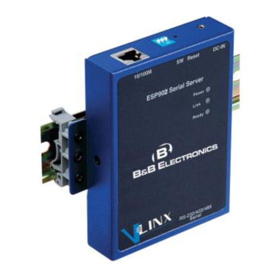
VLINX Models ESP901 and ESP902 Ethernet Serial Servers Ethernet to Serial connections for RS-232, RS-422 or RS-485 devices. The ESP901 features a single serial port and the ESP902 features two serial ports. The serial ports can be accessed over a LAN/WAN using , or connections. -
Page 10: Features
. Virtual COM port provides access to any of Ports (COM & LPT) the ports on the ESP901 and ESP902, like any other serial port (legacy, PCI, USB or PCMCIA) on the computer. Any program running on the computer and using Windows-based COM ports can access the serial devices attached to the . -
Page 11: Communication Modes
UDP/server with a designated communication port number. The virtual COM driver is the TCP or UDP client. Manual Documentation Number: ESP901-902_5012m Chapter 1 B&B Electronics Mfg Co Inc – 707 Dayton Rd - PO Box 1040 - Ottawa IL 61350 - Ph 815-433-5100 - Fax 815-433-5104 – www.bb-elec.com... -
Page 12: Paired Mode
UDP application. Chapter 1 Manual Documentation Number: ESP901-902_5012m B&B Electronics Mfg Co Inc – 707 Dayton Rd - PO Box 1040 - Ottawa IL 61350 - Ph 815-433-5100 - Fax 815-433-5104 – www.bb-elec.com B&B Electronics Ltd – Westlink Commercial Pk – Oranmore, Galway, Ireland – Ph +353 91-792444 – Fax +353 91-792445 – www.bb-europe.com... -
Page 13: Serial Server Quick Start Guide
Step 4: Apply power to the Serial Server Manual Documentation Number: ESP901-902_5012m Chapter 1 B&B Electronics Mfg Co Inc – 707 Dayton Rd - PO Box 1040 - Ottawa IL 61350 - Ph 815-433-5100 - Fax 815-433-5104 – www.bb-elec.com... -
Page 14: Software Installation
Search all reachable servers Chapter 1 Manual Documentation Number: ESP901-902_5012m B&B Electronics Mfg Co Inc – 707 Dayton Rd - PO Box 1040 - Ottawa IL 61350 - Ph 815-433-5100 - Fax 815-433-5104 – www.bb-elec.com B&B Electronics Ltd – Westlink Commercial Pk – Oranmore, Galway, Ireland – Ph +353 91-792444 – Fax +353 91-792445 – www.bb-europe.com... -
Page 15: Install Virtual Com Ports On Pc
Step 4: Communications with the serial device should now be operational. Manual Documentation Number: ESP901-902_5012m Chapter 1 B&B Electronics Mfg Co Inc – 707 Dayton Rd - PO Box 1040 - Ottawa IL 61350 - Ph 815-433-5100 - Fax 815-433-5104 – www.bb-elec.com... - Page 16 Introduction Chapter 1 Manual Documentation Number: ESP901-902_5012m B&B Electronics Mfg Co Inc – 707 Dayton Rd - PO Box 1040 - Ottawa IL 61350 - Ph 815-433-5100 - Fax 815-433-5104 – www.bb-elec.com B&B Electronics Ltd – Westlink Commercial Pk – Oranmore, Galway, Ireland – Ph +353 91-792444 – Fax +353 91-792445 – www.bb-europe.com...
-
Page 17: Chapter 2: Making The Hardware Connections
Package Checklist are shipped with the following ESP901 and ESP902 Serial Servers items included: ESP901 or ESP902 Serial Server Module Power supply This Operation Manual CD-ROM disc with manual, VLINX ESP Manager and Virtual COM Driver software for Windows 2000, XP, Server 2003, Vista, Server 2008 &... -
Page 18: Indicator Lights
Reset 2.5 mm Tip (+) Figure 6. Top View of ESP901 and ESP902 (when mounted vertically) Chapter 2 Manual Documentation Number: ESP901-902_5012m B&B Electronics Mfg Co Inc – 707 Dayton Rd - PO Box 1040 - Ottawa IL 61350 - Ph 815-433-5100 - Fax 815-433-5104 – www.bb-elec.com... -
Page 19: Dip Switches
Serial Server Console Mode, configuration of the (using an RS-232 connection Serial Server through the serial port on the ESP901 or Serial Port 1 on the ESP902) from a PC running a terminal program such as . When HyperTerminal enters... -
Page 20: Serial Ports
Port 2 The RS-232 interfaces are configured as DTEs. The connectors for all ports are DB-9M. Serial Port DB-9 Male Figure 8. The ESP901 Serial Port Connector Serial Port 1 Serial Port 2 DB-9 Male DB-9 Male Figure 9. The ESP902 Serial Port Connectors... -
Page 21: Default Mode
PC via its serial Upgrade Mode port to the ESP901 serial port or ESP902 Serial Port 1. Upgrading also can be accomplished via the network connection, using the ESP Manager software and a virtual COM port. -
Page 22: Rs-422 Mode
Chapter 2 Manual Documentation Number: ESP901-902_5012m B&B Electronics Mfg Co Inc – 707 Dayton Rd - PO Box 1040 - Ottawa IL 61350 - Ph 815-433-5100 - Fax 815-433-5104 – www.bb-elec.com B&B Electronics Ltd – Westlink Commercial Pk – Oranmore, Galway, Ireland – Ph +353 91-792444 – Fax +353 91-792445 – www.bb-europe.com... -
Page 23: Serial Server Serial Port Connector Pin-Outs
For more information on RS-232, RS-422 and RS-485 pin-outs, cable connections and loopback connections refer to Appendices A, B and C Manual Documentation Number: ESP901-902_5012m Chapter 2 B&B Electronics Mfg Co Inc – 707 Dayton Rd - PO Box 1040 - Ottawa IL 61350 - Ph 815-433-5100 - Fax 815-433-5104 – www.bb-elec.com... - Page 24 Making Hardware Connections Chapter 2 Manual Documentation Number: ESP901-902_5012m B&B Electronics Mfg Co Inc – 707 Dayton Rd - PO Box 1040 - Ottawa IL 61350 - Ph 815-433-5100 - Fax 815-433-5104 – www.bb-elec.com B&B Electronics Ltd – Westlink Commercial Pk – Oranmore, Galway, Ireland – Ph +353 91-792444 – Fax +353 91-792445 – www.bb-europe.com...
-
Page 25: Chapter 3: Installing The Vlinx Esp Software
The Run Dialogue Box window will be displayed. Install Shield Wizard Manual Documentation Number: ESP901-902_5012m Chapter 3 B&B Electronics Mfg Co Inc – 707 Dayton Rd - PO Box 1040 - Ottawa IL 61350 - Ph 815-433-5100 - Fax 815-433-5104 – www.bb-elec.com... - Page 26 The installation progress will be shown until complete. Chapter 3 Manual Documentation Number: ESP901-902_5012m B&B Electronics Mfg Co Inc – 707 Dayton Rd - PO Box 1040 - Ottawa IL 61350 - Ph 815-433-5100 - Fax 815-433-5104 – www.bb-elec.com B&B Electronics Ltd – Westlink Commercial Pk – Oranmore, Galway, Ireland – Ph +353 91-792444 – Fax +353 91-792445 – www.bb-europe.com...
-
Page 27: Updating An Existing Installation
Figure 17. The InstallShield Wizard Modify, Repair or Remove Screen Manual Documentation Number: ESP901-902_5012m Chapter 3 B&B Electronics Mfg Co Inc – 707 Dayton Rd - PO Box 1040 - Ottawa IL 61350 - Ph 815-433-5100 - Fax 815-433-5104 – www.bb-elec.com... -
Page 28: Opening The Esp Manager
ESP Manager Displaying all ESP90x Serial Servers Chapter 3 Manual Documentation Number: ESP901-902_5012m B&B Electronics Mfg Co Inc – 707 Dayton Rd - PO Box 1040 - Ottawa IL 61350 - Ph 815-433-5100 - Fax 815-433-5104 – www.bb-elec.com B&B Electronics Ltd – Westlink Commercial Pk – Oranmore, Galway, Ireland – Ph +353 91-792444 – Fax +353 91-792445 – www.bb-europe.com... -
Page 29: Chapter 4: Using Esp Manager
OFF position Figure 19. Ethernet Connection via a LAN Manual Documentation Number: ESP901-902_5012m Chapter 4 B&B Electronics Mfg Co Inc – 707 Dayton Rd - PO Box 1040 - Ottawa IL 61350 - Ph 815-433-5100 - Fax 815-433-5104 – www.bb-elec.com... -
Page 30: Software Setup
Serial Servers Chapter 4 Manual Documentation Number: ESP901-902_5012m B&B Electronics Mfg Co Inc – 707 Dayton Rd - PO Box 1040 - Ottawa IL 61350 - Ph 815-433-5100 - Fax 815-433-5104 – www.bb-elec.com B&B Electronics Ltd – Westlink Commercial Pk – Oranmore, Galway, Ireland – Ph +353 91-792444 – Fax +353 91-792445 – www.bb-europe.com... -
Page 31: Software Overview
COM settings must match port settings. Serial Server Manual Documentation Number: ESP901-902_5012m Chapter 4 B&B Electronics Mfg Co Inc – 707 Dayton Rd - PO Box 1040 - Ottawa IL 61350 - Ph 815-433-5100 - Fax 815-433-5104 – www.bb-elec.com B&B Electronics Ltd – Westlink Commercial Pk – Oranmore, Galway, Ireland – Ph +353 91-792444 – Fax +353 91-792445 – www.bb-europe.com... - Page 32 Chapter 4 Manual Documentation Number: ESP901-902_5012m B&B Electronics Mfg Co Inc – 707 Dayton Rd - PO Box 1040 - Ottawa IL 61350 - Ph 815-433-5100 - Fax 815-433-5104 – www.bb-elec.com B&B Electronics Ltd – Westlink Commercial Pk – Oranmore, Galway, Ireland – Ph +353 91-792444 – Fax +353 91-792445 – www.bb-europe.com...
-
Page 33: Server Icons Pane
- Displays the currently selected TCP or UDP mode for Protocol Serial Server Manual Documentation Number: ESP901-902_5012m Chapter 4 B&B Electronics Mfg Co Inc – 707 Dayton Rd - PO Box 1040 - Ottawa IL 61350 - Ph 815-433-5100 - Fax 815-433-5104 – www.bb-elec.com... -
Page 34: Status Bar
The Search Setup Window Chapter 4 Manual Documentation Number: ESP901-902_5012m B&B Electronics Mfg Co Inc – 707 Dayton Rd - PO Box 1040 - Ottawa IL 61350 - Ph 815-433-5100 - Fax 815-433-5104 – www.bb-elec.com B&B Electronics Ltd – Westlink Commercial Pk – Oranmore, Galway, Ireland – Ph +353 91-792444 – Fax +353 91-792445 – www.bb-europe.com... -
Page 35: Configure Server Properties
Server configuration settings. Details for setting Properties are described in the next chapter. Manual Documentation Number: ESP901-902_5012m Chapter 4 B&B Electronics Mfg Co Inc – 707 Dayton Rd - PO Box 1040 - Ottawa IL 61350 - Ph 815-433-5100 - Fax 815-433-5104 – www.bb-elec.com... - Page 36 Step 8: Chapter 4 Manual Documentation Number: ESP901-902_5012m B&B Electronics Mfg Co Inc – 707 Dayton Rd - PO Box 1040 - Ottawa IL 61350 - Ph 815-433-5100 - Fax 815-433-5104 – www.bb-elec.com B&B Electronics Ltd – Westlink Commercial Pk – Oranmore, Galway, Ireland – Ph +353 91-792444 – Fax +353 91-792445 – www.bb-europe.com...
- Page 37 Each port must be configured separately. Manual Documentation Number: ESP901-902_5012m Chapter 4 B&B Electronics Mfg Co Inc – 707 Dayton Rd - PO Box 1040 - Ottawa IL 61350 - Ph 815-433-5100 - Fax 815-433-5104 – www.bb-elec.com...
- Page 38 Using ESP Manager Chapter 4 Manual Documentation Number: ESP901-902_5012m B&B Electronics Mfg Co Inc – 707 Dayton Rd - PO Box 1040 - Ottawa IL 61350 - Ph 815-433-5100 - Fax 815-433-5104 – www.bb-elec.com B&B Electronics Ltd – Westlink Commercial Pk – Oranmore, Galway, Ireland – Ph +353 91-792444 – Fax +353 91-792445 – www.bb-europe.com...
-
Page 39: Chapter 5: Configuring The Serial Server Properties
Figure 29. The Four Methods of Configuring Server Properties Manual Documentation Number: ESP901-902_5012m Chapter 5 B&B Electronics Mfg Co Inc – 707 Dayton Rd - PO Box 1040 - Ottawa IL 61350 - Ph 815-433-5100 - Fax 815-433-5104 – www.bb-elec.com... -
Page 40: Description Of The Server Properties
DHCP request to the DHCP server, which will assign a dynamic IP Chapter 5 Manual Documentation Number: ESP901-902_5012m B&B Electronics Mfg Co Inc – 707 Dayton Rd - PO Box 1040 - Ottawa IL 61350 - Ph 815-433-5100 - Fax 815-433-5104 – www.bb-elec.com... -
Page 41: Ip Address
- The command will return the Ping results indicating 4 replies Figure 31. Pinging using the DOS command window Manual Documentation Number: ESP901-902_5012m Chapter 5 B&B Electronics Mfg Co Inc – 707 Dayton Rd - PO Box 1040 - Ottawa IL 61350 - Ph 815-433-5100 - Fax 815-433-5104 – www.bb-elec.com... -
Page 42: Netmask
Virtual COM Mode is not being used. Chapter 5 Manual Documentation Number: ESP901-902_5012m B&B Electronics Mfg Co Inc – 707 Dayton Rd - PO Box 1040 - Ottawa IL 61350 - Ph 815-433-5100 - Fax 815-433-5104 – www.bb-elec.com B&B Electronics Ltd – Westlink Commercial Pk – Oranmore, Galway, Ireland – Ph +353 91-792444 – Fax +353 91-792445 – www.bb-europe.com... -
Page 43: Flow Control
Client Manual Documentation Number: ESP901-902_5012m Chapter 5 B&B Electronics Mfg Co Inc – 707 Dayton Rd - PO Box 1040 - Ottawa IL 61350 - Ph 815-433-5100 - Fax 815-433-5104 – www.bb-elec.com B&B Electronics Ltd – Westlink Commercial Pk – Oranmore, Galway, Ireland – Ph +353 91-792444 – Fax +353 91-792445 – www.bb-europe.com... -
Page 44: Tcp Alive Timeout
Ethernet port. If only Delimiter 1 is set (Delimiter 2 is zero or blank), upon receiving Delimiter 1 the ESP901/902 will put all the data in the serial buffer in an Ethernet packet and send it out the Ethernet port. -
Page 45: Port Status
Serial Server Console Mode port (the serial Port on ESP901 or Port 1 on ESP902), displaying screen and allowing configuration of the Server Properties server and its ports. – When this mode is selected and the server is updated,... -
Page 46: Connection At
Connection At When the field is set to Connection Mode Client Client (no , this field becomes active, allowing the ESP901/902 (acting heartbeat) as a client) to connect to the server either on or on Power up Data (first character arriving). - Page 47 Figure 36. The Search VLINX ESP Dialogue Box Manual Documentation Number: ESP901-902_5012m Chapter 5 B&B Electronics Mfg Co Inc – 707 Dayton Rd - PO Box 1040 - Ottawa IL 61350 - Ph 815-433-5100 - Fax 815-433-5104 – www.bb-elec.com...
- Page 48 Chapter 5 Manual Documentation Number: ESP901-902_5012m B&B Electronics Mfg Co Inc – 707 Dayton Rd - PO Box 1040 - Ottawa IL 61350 - Ph 815-433-5100 - Fax 815-433-5104 – www.bb-elec.com B&B Electronics Ltd – Westlink Commercial Pk – Oranmore, Galway, Ireland – Ph +353 91-792444 – Fax +353 91-792445 – www.bb-europe.com...
-
Page 49: Web Server
If you leave any Web Server page without saving, any changes you have made will be ignored. Manual Documentation Number: ESP901-902_5012m Chapter 5 B&B Electronics Mfg Co Inc – 707 Dayton Rd - PO Box 1040 - Ottawa IL 61350 - Ph 815-433-5100 - Fax 815-433-5104 – www.bb-elec.com... - Page 50 Server Properties Configuration Chapter 5 Manual Documentation Number: ESP901-902_5012m B&B Electronics Mfg Co Inc – 707 Dayton Rd - PO Box 1040 - Ottawa IL 61350 - Ph 815-433-5100 - Fax 815-433-5104 – www.bb-elec.com B&B Electronics Ltd – Westlink Commercial Pk – Oranmore, Galway, Ireland – Ph +353 91-792444 – Fax +353 91-792445 – www.bb-europe.com...
-
Page 51: Chapter 6: Installing Virtual Com Ports
Search all reachable servers Figure 38. The Search Setup Window Manual Documentation Number: ESP901-902_5012m Chapter 6 B&B Electronics Mfg Co Inc – 707 Dayton Rd - PO Box 1040 - Ottawa IL 61350 - Ph 815-433-5100 - Fax 815-433-5104 – www.bb-elec.com... - Page 52 Logo testing. Chapter 6 Manual Documentation Number: ESP901-902_5012m B&B Electronics Mfg Co Inc – 707 Dayton Rd - PO Box 1040 - Ottawa IL 61350 - Ph 815-433-5100 - Fax 815-433-5104 – www.bb-elec.com B&B Electronics Ltd – Westlink Commercial Pk – Oranmore, Galway, Ireland – Ph +353 91-792444 – Fax +353 91-792445 – www.bb-europe.com...
- Page 53 The Serial Server must be set to match. Manual Documentation Number: ESP901-902_5012m Chapter 6 B&B Electronics Mfg Co Inc – 707 Dayton Rd - PO Box 1040 - Ottawa IL 61350 - Ph 815-433-5100 - Fax 815-433-5104 – www.bb-elec.com...
-
Page 54: Matching The Serial Server And Virtual Com Port Settings
Properties Chapter 6 Manual Documentation Number: ESP901-902_5012m B&B Electronics Mfg Co Inc – 707 Dayton Rd - PO Box 1040 - Ottawa IL 61350 - Ph 815-433-5100 - Fax 815-433-5104 – www.bb-elec.com B&B Electronics Ltd – Westlink Commercial Pk – Oranmore, Galway, Ireland – Ph +353 91-792444 – Fax +353 91-792445 – www.bb-europe.com... - Page 55 Device Manager if Windows does not auto refresh. Manual Documentation Number: ESP901-902_5012m Chapter 6 B&B Electronics Mfg Co Inc – 707 Dayton Rd - PO Box 1040 - Ottawa IL 61350 - Ph 815-433-5100 - Fax 815-433-5104 – www.bb-elec.com...
- Page 56 Installing Virtual COM Port Chapter 6 Manual Documentation Number: ESP901-902_5012m B&B Electronics Mfg Co Inc – 707 Dayton Rd - PO Box 1040 - Ottawa IL 61350 - Ph 815-433-5100 - Fax 815-433-5104 – www.bb-elec.com B&B Electronics Ltd – Westlink Commercial Pk – Oranmore, Galway, Ireland – Ph +353 91-792444 – Fax +353 91-792445 – www.bb-europe.com...
-
Page 57: Chapter 7: Removing Virtual Com Ports
Highlight the mapped COM port number to be removed. Figure 44. The ESP Manager Window Manual Documentation Number: ESP901-902_5012m Chapter 7 B&B Electronics Mfg Co Inc – 707 Dayton Rd - PO Box 1040 - Ottawa IL 61350 - Ph 815-433-5100 - Fax 815-433-5104 – www.bb-elec.com... -
Page 58: Removing The Virtual Com Port Using Device Manager
System Chapter 7 Manual Documentation Number: ESP901-902_5012m B&B Electronics Mfg Co Inc – 707 Dayton Rd - PO Box 1040 - Ottawa IL 61350 - Ph 815-433-5100 - Fax 815-433-5104 – www.bb-elec.com B&B Electronics Ltd – Westlink Commercial Pk – Oranmore, Galway, Ireland – Ph +353 91-792444 – Fax +353 91-792445 – www.bb-europe.com... - Page 59 Device window will appear. Removal Manual Documentation Number: ESP901-902_5012m Chapter 7 B&B Electronics Mfg Co Inc – 707 Dayton Rd - PO Box 1040 - Ottawa IL 61350 - Ph 815-433-5100 - Fax 815-433-5104 – www.bb-elec.com B&B Electronics Ltd – Westlink Commercial Pk – Oranmore, Galway, Ireland – Ph +353 91-792444 – Fax +353 91-792445 – www.bb-europe.com...
- Page 60 COM ports Chapter 7 Manual Documentation Number: ESP901-902_5012m B&B Electronics Mfg Co Inc – 707 Dayton Rd - PO Box 1040 - Ottawa IL 61350 - Ph 815-433-5100 - Fax 815-433-5104 – www.bb-elec.com B&B Electronics Ltd – Westlink Commercial Pk – Oranmore, Galway, Ireland – Ph +353 91-792444 – Fax +353 91-792445 – www.bb-europe.com...
-
Page 61: Chapter 8: Upgrading The Serial Server Firmware
ESP Manager using a direct PC connection via the ESP901 serial port, ESP902 Port 1, or using a virtual COM port. If connecting directly to a computer serial port, use a null modem cable between the Computer RS-232 port and the ESP901 serial port or ESP902 Port 1. -
Page 62: Upgrading The Firmware
Click Chapter 8 Manual Documentation Number: ESP901-902_5012m B&B Electronics Mfg Co Inc – 707 Dayton Rd - PO Box 1040 - Ottawa IL 61350 - Ph 815-433-5100 - Fax 815-433-5104 – www.bb-elec.com B&B Electronics Ltd – Westlink Commercial Pk – Oranmore, Galway, Ireland – Ph +353 91-792444 – Fax +353 91-792445 – www.bb-europe.com... -
Page 63: Chapter 9: Using Console Mode
Manual Documentation Number: ESP901-902_5012m Chapter 9 B&B Electronics Mfg Co Inc – 707 Dayton Rd - PO Box 1040 - Ottawa IL 61350 - Ph 815-433-5100 - Fax 815-433-5104 – www.bb-elec.com... -
Page 64: Navigating The Configuration Menus
Console Mode Configuration Screens Chapter 9 Manual Documentation Number: ESP901-902_5012m B&B Electronics Mfg Co Inc – 707 Dayton Rd - PO Box 1040 - Ottawa IL 61350 - Ph 815-433-5100 - Fax 815-433-5104 – www.bb-elec.com B&B Electronics Ltd – Westlink Commercial Pk – Oranmore, Galway, Ireland – Ph +353 91-792444 – Fax +353 91-792445 – www.bb-europe.com... -
Page 65: Using A Password
Reset Manual Documentation Number: ESP901-902_5012m Chapter 9 B&B Electronics Mfg Co Inc – 707 Dayton Rd - PO Box 1040 - Ottawa IL 61350 - Ph 815-433-5100 - Fax 815-433-5104 – www.bb-elec.com B&B Electronics Ltd – Westlink Commercial Pk – Oranmore, Galway, Ireland – Ph +353 91-792444 – Fax +353 91-792445 – www.bb-europe.com... - Page 66 Using Console Mode Chapter 9 Manual Documentation Number: ESP901-902_5012m B&B Electronics Mfg Co Inc – 707 Dayton Rd - PO Box 1040 - Ottawa IL 61350 - Ph 815-433-5100 - Fax 815-433-5104 – www.bb-elec.com B&B Electronics Ltd – Westlink Commercial Pk – Oranmore, Galway, Ireland – Ph +353 91-792444 – Fax +353 91-792445 – www.bb-europe.com...
-
Page 67: Chapter 10: Using The Web Server
Figure 52. The Web Server Page Manual Documentation Number: ESP901-902_5012m Chapter 10 B&B Electronics Mfg Co Inc – 707 Dayton Rd - PO Box 1040 - Ottawa IL 61350 - Ph 815-433-5100 - Fax 815-433-5104 – www.bb-elec.com... - Page 68 The following page will appear: Chapter 10 Manual Documentation Number: ESP901-902_5012m B&B Electronics Mfg Co Inc – 707 Dayton Rd - PO Box 1040 - Ottawa IL 61350 - Ph 815-433-5100 - Fax 815-433-5104 – www.bb-elec.com...
- Page 69 Server the browser window. Manual Documentation Number: ESP901-902_5012m Chapter 10 B&B Electronics Mfg Co Inc – 707 Dayton Rd - PO Box 1040 - Ottawa IL 61350 - Ph 815-433-5100 - Fax 815-433-5104 – www.bb-elec.com...
- Page 70 Using the Web Server Chapter 10 Manual Documentation Number: ESP901-902_5012m B&B Electronics Mfg Co Inc – 707 Dayton Rd - PO Box 1040 - Ottawa IL 61350 - Ph 815-433-5100 - Fax 815-433-5104 – www.bb-elec.com B&B Electronics Ltd – Westlink Commercial Pk – Oranmore, Galway, Ireland – Ph +353 91-792444 – Fax +353 91-792445 – www.bb-europe.com...
-
Page 71: Chapter 11: Using Telnet
Console mode you may not be able to access it using Telnet. In this case use ESP Manager, Console Mode or Web Server for configuration. Manual Documentation Number: ESP901-902_5012m Chapter 11 B&B Electronics Mfg Co Inc – 707 Dayton Rd - PO Box 1040 - Ottawa IL 61350 - Ph 815-433-5100 - Fax 815-433-5104 – www.bb-elec.com... -
Page 72: Navigating The Configuration Menu
Space Bar Chapter 11 Manual Documentation Number: ESP901-902-5012m B&B Electronics Mfg Co Inc – 707 Dayton Rd - PO Box 1040 - Ottawa IL 61350 - Ph 815-433-5100 - Fax 815-433-5104 – www.bb-elec.com B&B Electronics Ltd – Westlink Commercial Pk – Oranmore, Galway, Ireland – Ph +353 91-792444 – Fax +353 91-792445 – www.bb-europe.com... -
Page 73: Using Telnet
Using Telnet Figure 56. Telnet Configuration Screens Manual Documentation Number: ESP901-902_5012m Chapter 11 B&B Electronics Mfg Co Inc – 707 Dayton Rd - PO Box 1040 - Ottawa IL 61350 - Ph 815-433-5100 - Fax 815-433-5104 – www.bb-elec.com B&B Electronics Ltd – Westlink Commercial Pk – Oranmore, Galway, Ireland – Ph +353 91-792444 – Fax +353 91-792445 – www.bb-europe.com... - Page 74 Chapter 11 Manual Documentation Number: ESP901-902-5012m B&B Electronics Mfg Co Inc – 707 Dayton Rd - PO Box 1040 - Ottawa IL 61350 - Ph 815-433-5100 - Fax 815-433-5104 – www.bb-elec.com B&B Electronics Ltd – Westlink Commercial Pk – Oranmore, Galway, Ireland – Ph +353 91-792444 – Fax +353 91-792445 – www.bb-europe.com...
-
Page 75: Chapter 12: Esp901 And Esp902 Technical Data
VLINX ESP Manager and Virtual COM Driver software for Windows 2000, XP, Server 2003, Vista, Server 2008 & Win 7 Dimensions ESP901/ESP902: 3.4 x 4.5 x 0.90 in (8.5 x 11.5 x 2.3 cm) Power & Power Requirements: 12 VDC @ 200 mA (ESP901), 300mA... - Page 76 ESP901 and ESP902 Technical Data RS-232(DTE): TXD, RXD, RTS, CTS, DTR, DSR, DCD, Serial Interfaces RS-422: TXDB(+), TXDA(−), RXDB(+), RXDA(−), RTS(+), RTS(−), CTS(+), CTS(−) and GND RS-485: Data B (+), Data A (–) and GND Baud Rate: 110 bps to 230.4 k bps...
- Page 77 ESP901 and ESP902 Technical Data Server Name ESP901 or ESP902 Default Server Settings Serial Number: xxxxxxxxx (printed on bottom of unit) Password: Blank DHCP: Disable IP Address: 192.168.0.1 Net Mask: 255.255.255.0 Gateway: 192.168.0.254 Fixed – see bottom label MAC Address: Version&Date:...
- Page 78 ESP901 and ESP902 Technical Data Figure 58. Dimensional Diagram of the ESP901 Figure 59. Dimensional Diagram of the ESP902 Chapter 12 Manual Documentation Number: ESP901-902_5012m B&B Electronics Mfg Co Inc – 707 Dayton Rd - PO Box 1040 - Ottawa IL 61350 - Ph 815-433-5100 - Fax 815-433-5104 – www.bb-elec.com...
-
Page 79: Appendix A: Rs-232 Connections
Ring Indicator Figure 60. RS-232 Connections in a DB-9 Connector Manual Documentation Number: ESP901-902_5012m Appendix A B&B Electronics Mfg Co Inc – 707 Dayton Rd - PO Box 1040 - Ottawa IL 61350 - Ph 815-433-5100 - Fax 815-433-5104 – www.bb-elec.com... -
Page 80: Rs-232 Straight-Through Cable Connections
Figure 62. Crossover DB-9 to DB-9 RS-232 Serial Cable Appendix A Manual Documentation Number: ESP901-902_5012m B&B Electronics Mfg Co Inc – 707 Dayton Rd - PO Box 1040 - Ottawa IL 61350 - Ph 815-433-5100 - Fax 815-433-5104 – www.bb-elec.com... -
Page 81: Rs-232 Straight-Through Db-9 To Db-25 Conversion Connections
Figure 64. DB-9 to DB-25 Crossover (null modem) Cable Connections Manual Documentation Number: ESP901-902_5012m Appendix A B&B Electronics Mfg Co Inc – 707 Dayton Rd - PO Box 1040 - Ottawa IL 61350 - Ph 815-433-5100 - Fax 815-433-5104 – www.bb-elec.com... -
Page 82: Rs-232 Dte Loopback Connections
Carrier. Appendix A Manual Documentation Number: ESP901-902_5012m B&B Electronics Mfg Co Inc – 707 Dayton Rd - PO Box 1040 - Ottawa IL 61350 - Ph 815-433-5100 - Fax 815-433-5104 – www.bb-elec.com B&B Electronics Ltd – Westlink Commercial Pk – Oranmore, Galway, Ireland – Ph +353 91-792444 – Fax +353 91-792445 – www.bb-europe.com... -
Page 83: Appendix B: Rs-422 Connections
RTSA (−) Figure 66. RS-422 Connections in a DB-9 Connector Manual Documentation Number: ESP901-902_5012m Appendix B B&B Electronics Mfg Co Inc – 707 Dayton Rd - PO Box 1040 - Ottawa IL 61350 - Ph 815-433-5100 - Fax 815-433-5104 – www.bb-elec.com... - Page 84 RTS/CTS line pairs. Appendix B Manual Documentation Number: ESP901-902_5012m B&B Electronics Mfg Co Inc – 707 Dayton Rd - PO Box 1040 - Ottawa IL 61350 - Ph 815-433-5100 - Fax 815-433-5104 – www.bb-elec.com B&B Electronics Ltd – Westlink Commercial Pk – Oranmore, Galway, Ireland – Ph +353 91-792444 – Fax +353 91-792445 – www.bb-europe.com...
- Page 85 Figure 69. RS-422 Connection with No Flow Control Manual Documentation Number: ESP901-902_5012m Appendix B B&B Electronics Mfg Co Inc – 707 Dayton Rd - PO Box 1040 - Ottawa IL 61350 - Ph 815-433-5100 - Fax 815-433-5104 – www.bb-elec.com...
- Page 86 RS-422 Connections Appendix B Manual Documentation Number: ESP901-902_5012m B&B Electronics Mfg Co Inc – 707 Dayton Rd - PO Box 1040 - Ottawa IL 61350 - Ph 815-433-5100 - Fax 815-433-5104 – www.bb-elec.com B&B Electronics Ltd – Westlink Commercial Pk – Oranmore, Galway, Ireland – Ph +353 91-792444 – Fax +353 91-792445 – www.bb-europe.com...
-
Page 87: Appendix C: Rs-485 Connections
Serial Server used, as it does not tri-state the transmitter in RS-422 mode. Manual Documentation Number: ESP901-902_5012m Appendix C B&B Electronics Mfg Co Inc – 707 Dayton Rd - PO Box 1040 - Ottawa IL 61350 - Ph 815-433-5100 - Fax 815-433-5104 – www.bb-elec.com... - Page 88 RS-485 Connections Appendix D Manual Documentation Number: ESP901-902_5012m B&B Electronics Mfg Co Inc – 707 Dayton Rd - PO Box 1040 - Ottawa IL 61350 - Ph 815-433-5100 - Fax 815-433-5104 – www.bb-elec.com B&B Electronics Ltd – Westlink Commercial Pk – Oranmore, Galway, Ireland – Ph +353 91-792444 – Fax +353 91-792445 – www.bb-europe.com...
-
Page 89: Appendix D: Network Connections
Brown Figure 72. Pin-out for a Standard Ethernet Cable Manual Documentation Number: ESP901-902_5012m Appendix D B&B Electronics Mfg Co Inc – 707 Dayton Rd - PO Box 1040 - Ottawa IL 61350 - Ph 815-433-5100 - Fax 815-433-5104 – www.bb-elec.com... -
Page 90: Crossover Ethernet Cable Rj-45 Pin-Out
Pin-out for a Crossover Ethernet Cable Appendix D Manual Documentation Number: ESP901-902_5012m B&B Electronics Mfg Co Inc – 707 Dayton Rd - PO Box 1040 - Ottawa IL 61350 - Ph 815-433-5100 - Fax 815-433-5104 – www.bb-elec.com B&B Electronics Ltd – Westlink Commercial Pk – Oranmore, Galway, Ireland – Ph +353 91-792444 – Fax +353 91-792445 – www.bb-europe.com... - Page 91 © B&B Electronics – December 2010 Manual Documentation Number: ESP901-902_5012m B&B Electronics Mfg Co Inc – 707 Dayton Rd - PO Box 1040 - Ottawa IL 61350 - Ph 815-433-5100 - Fax 815-433-5104 – www.bb-elec.com B&B Electronics Ltd – Westlink Commercial Pk – Oranmore, Galway, Ireland – Ph +353 91-792444 – Fax +353 91-792445 – www.bb-europe.com...
Need help?
Do you have a question about the ESP901 and is the answer not in the manual?
Questions and answers