Table of Contents
Advertisement
Advertisement
Table of Contents

Related Manuals for MSI K8NM-FISR


Summary of Contents for MSI K8NM-FISR
- Page 1 K8NM Series MS-7034 (v1.X) M-ATX Mainboard G52-M7034X3...
-
Page 2: Fcc-B Radio Frequency Interference Statement
Manual Rev: 1.2 Release Date: July 2004 FCC-B Radio Frequency Interference Statement This equipment has been tested and found to comply with the limits for a class B digital device, pursuant to part 15 of the FCC rules. These limits are designed to provide reasonable protection against harmful interference when the equipment is operated in a commercial environment. -
Page 3: Copyright Notice
Copyright Notice The material in this document is the intellectual property of MICRO-STAR INTERNATIONAL. We take every care in the preparation of this document, but no guarantee is given as to the correctness of its contents. Our products are under continual improvement and we reserve the right to make changes without notice. -
Page 4: Technical Support
Alternatively, please try the following help resources for further guidance. Visit the MSI homepage & FAQ site for technical guide, BIOS updates, driver updates, and other information: http://www.msi.com.tw & http://www.msi. -
Page 5: Table Of Contents
CONTENTS FCC-B Radio Frequency Interference Statement ............ii Copyright Notice ......................iii Revision History ......................iii Technical Support ......................iv Safety Instructions ...................... iv Chapter 1. Getting Started ................... 1-1 Mainboard Specifications .................. 1-2 Mainboard Layout ....................1-4 Packing Contents ....................1-5 Chapter 2. - Page 6 Front USB Connectors: JUSB1/JUSB2 ............ 2-20 Front Panel Audio Connector: JAUD1 ............. 2-20 CD-In Connector: JCD1 ................2-21 SPDIF Connector: JSP1 ................2-21 IEEE 1394 Connector: J1394_1 (optional) ..........2-22 Jumpers ......................2-23 Clear CMOS Jumper: JBAT1 ..............2-23 Slots ........................2-24 AGP (Accelerated Graphics Port) Slot ...........
- Page 7 Installing the RAID Driver (for bootable RAID Array) ....... 4-8 Initializing and Using the Disk Array ............4-10 RAID Drives Management ................4-12 Viewing RAID Array Configurations ............4-12 Setting Up a Spare RAID Disk ..............4-14 Rebuilding a RAID Mirrored Array ............4-20 Chapter 5.
-
Page 8: Chapter 1. Getting Started
Getting Started Chapter 1. Getting Started Getting Started Thank you for choosing the K8NM (MS-7034) v1.X Micro ATX ® mainboard. The K8NM mainboard is based on NVIDIA nForce™3 250 chipset for optimal system efficiency. Designed to fit the ad- vanced AMD ®... -
Page 9: Mainboard Specifications
MS-7034 M-ATX Mainboard Mainboard Specifications Supports 64-bit Athlon64 (Socket-754) for AMD K8 Athlon™ processor up to 3700 (For the latest information about CPU, please visit http://www.msi.com.tw/program/ products/mainboard/mbd/pro_mbd_cpu_support.php) Chipset NVIDIA nForce3 250 - HyperTransport link to the AMD Athlon 64 CPU - HyperTransport @ 800MHz, running at up to 6400MB/s - AGP3.0 8X interface at 533 MT/s (million transfers per second) - Page 10 Micro-ATX Form Factor: 24.5 cm (L) x 24.5 cm (W) 9 mounting holes MSI Reminds You... 1. Please note that users cannot install OS, either WinME or Win98, in their SATA hard drive. Under these two OSs, SATA can only be used as a normal storage device.
-
Page 11: Mainboard Layout
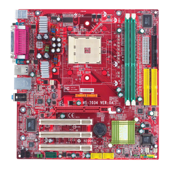
MS-7034 M-ATX Mainboard Mainboard Layout T: mouse B: keyboard FDD1 JPW1 C_FAN1 SATA2 SATA1 REALTEK RTL8201CL/ Line-In 8100S Co-lay Line-Out B:Mic AGP Slot IDE 2 IDE 1 DDR1 DDR2 NB_FAN1 PCI Slot 1 VT6307 NVIDIA PCI Slot 2 nFORCE3 BIOS Codec PCI Slot 3 JCD1... -
Page 12: Packing Contents
Getting Started Packing Contents MSI Driver/Utility CD SATA Cable MSI motherboard Round Cable of Power Cable D-Bracket 2 (optional) IDE Devices Round Cable of User’s Guide Back IO Shield Floppy Disk... -
Page 13: Chapter 2. Hardware Setup
Hardware Setup Chapter 2. Hardware Setup Hardware Setup This chapter tells you how to install the CPU, memory modules, and expansion cards, as well as how to setup the jumpers on the mainboard. Also, it provides the instructions on connecting the periph- eral devices, such as the mouse, keyboard, etc. -
Page 14: Quick Components Guide
MS-7034 M-ATX Mainboard Quick Components Guide DDR DIMMs, p.2-7 JPW1, p.2-9 C_FAN1, p.2-15 CPU, p.2-3 JLED1, p.2-19 JWR1, p.2-9 Back Panel FDD1, I/O, p.2-11 p.2-15 SATA1, SATA2, IDE1/2, p.2-17 p.2-16 AGP1, p.2-24 NB_FAN1, p.2-15 PCI Slots 1~3, p.2-24 S_FAN1, JCD1, p.2-21 p.2-15 JSP1, p.2-21 JFP2, p.2-18... -
Page 15: Central Processing Unit: Cpu
If you do not have the heat sink and cooling fan, contact your dealer to purchase and install them before turning on the computer. For the latest information about CPU, please visit http://www.msi.com.tw/ program/products/mainboard/mbd/pro_mbd_cpu_support.php. MSI Reminds You... -
Page 16: Cpu Installation Procedures For Socket 754
MS-7034 M-ATX Mainboard CPU Installation Procedures for Socket 754 1. Please turn off the power and Open Lever unplug the power cord before installing the CPU. Sliding 90 degree Plate 2. Pull the lever sideways away from the socket. Make sure to raise the lever up to a 90-degree angle. -
Page 17: Installing Amd Athlon64 Cpu Cooler Set
Hardware Setup Installing AMD Athlon64 CPU Cooler Set When you are installing the CPU, make sure the CPU has a heat sink and a cooling fan attached on the top to prevent overheating. If you do not have the heat sink and cooling fan, contact your dealer to purchase and install them before turning on the computer. - Page 18 7. Locate the Fix Lever, Safety Hook and the Fixed Bolt. Lift up the in- tensive fixed lever. MSI Reminds You... While disconnecting the Safety Hook from the fixed bolt, it is necessary to keep an eye on Safety Hook...
-
Page 19: Memory
The mainboard provides two 184-pin unbuffered DDR266/DDR333/DDR400 DDR SDRAM, and supports the memory size up to 2GB without ECC. To operate properly, at least one DIMM module must be installed. For the updated supporting memory modules, please visit http://www.msi. com.tw/program/products/mainboard/mbd/pro_mbd_trp_list.php. DDR DIMM Slots... -
Page 20: Ddr Module Combination
The plastic clip at each side of the DIMM slot will automatically close. Notch Volt MSI Reminds You... You can barely see the golden finger if the module is properly inserted into the socket. -
Page 21: Power Supply
JPW1 Pin Definition SIGNAL JPW1 MSI Reminds You... 1. These two connectors connect to the ATX power supply and have to work together to ensure stable operation of the mainboard. 2. Power supply of 300 watts (and above) is highly recommended for... -
Page 22: Important Notification About Power Issue
MS-7034 M-ATX Mainboard Important Notification about Power Issue NForce chipset is very sensitive to ESD (Electrostatic Discharge), therefore this issue mostly happens while the users intensively swap memory modules under S5 (power-off) states, and the power code is plugged while installing modules. Due to several pins are very sensitive to ESD, so this kind of memory-replacement actions might cause chipset system unable to boot. -
Page 23: Back Panel
Hardware Setup Back Panel The back panel provides the following connectors: L-in L-out 1394 Parallel Mouse (optional) Keyboard COM1 COM2 USB Port USB Port Mouse/Keyboard Connector ® The mainboard provides a standard PS/2 mouse/keyboard mini DIN connector ® ® for attaching a PS/2 mouse/keyboard. -
Page 24: Serial Port Connector: Com Ports
MS-7034 M-ATX Mainboard Serial Port Connector: COM ports The mainboard offers two 9-pin male DIN connectors as the serial ports. The ports are 16550A high speed communication ports that send/receive 16 bytes FIFOs. You can attach a serial mouse or other serial devices directly to the connectors. Pin Definition 1 2 3 4 5 SIGNAL... -
Page 25: Lan (Rj-45) Jack (Optional)
Line In 1/8” Stereo Audio Connectors Line Out MSI Reminds You... For advanced audio application, Realtek ALC 655 is provided to offer support for 6-channel audio operation and can turn rear audio connectors from 2-channel to 4-/6-channel audio. For more information on 6-channel audio operation, please refer to Appendix. -
Page 26: Parallel Port Connector: Lpt1
MS-7034 M-ATX Mainboard Parallel Port Connector: LPT1 The mainboard provides a 25-pin female centronic connector as LPT. A parallel port is a standard printer port that supports Enhanced Parallel Port (EPP) and Ex- tended Capabilities Parallel Port (ECP) mode. Pin Definition SIGNAL DESCRIPTION STROBE... -
Page 27: Connectors
C_FAN1 S_FAN1 S_FAN2 NB_FAN1 MSI Reminds You... 1. Always consult the vendors for proper CPU cooling fan. 2. C_FAN1 supports the fan control. You can install Core Center utility that will automatically control the CPU fan speed according to the actual CPU temperature. -
Page 28: Hard Disk Connectors: Ide1/Ide2
IDE2 (Secondary IDE Connector) IDE2 can also connect a Master and a Slave drive. MSI Reminds You... If you install two hard disks on cable, you must configure the second drive to Slave mode by setting its jumper. Refer to the hard disk documentation supplied by hard disk vendors for jumper setting instructions. -
Page 29: Serial Ata Hdd Connectors: Sata1/Sata2
Take out the dust cover and connect to the hard disk devices Optional Serial ATA cable Connect to SATA1 or SATA2 MSI Reminds You... Please do not fold the Serial ATA cable into 90-degree angle. Otherwise, the loss of data may occur during transmission. 2-17... -
Page 30: Front Panel Connectors: Jfp1/Jfp2
MS-7034 M-ATX Mainboard Front Panel Connectors: JFP1/JFP2 The mainboard provides two front panel connectors for electrical connection ® to the front panel switches and LEDs. JFP1 is compliant with Intel Front Panel I/O Connectivity Design Guide. Power Power Speaker Switch JFP2 JFP1 Power... -
Page 31: D-Bracket™ 2 Connector: Jled1
Hardware Setup D-Bracket™ 2 Connector: JLED1 The mainboard comes with a JLED1 connector for you to connect to D-Bracket™ 2. D-Bracket™ 2 is a USB Bracket that supports both USB1.1 & 2.0 spec. It integrates four LEDs and allows users to identify system problem through 16 various combina- tions of LED signals. -
Page 32: Front Usb Connectors: Jusb1/Jusb2
Left channel audio signal to front panel AUD_RET_L Left channel audio signal return from front panel MSI Reminds You... If you don’t want to connect to the front audio header, pins 5 & 6, 9 & 10 have to be jumpered in order to have signal output directed to the rear audio ports. -
Page 33: Cd-In Connector: Jcd1
Hardware Setup CD-In Connector: JCD1 The connector is for CD-ROM audio connector. JCD1 SPDIF Connector: JSP1 The connector is used to connect SPDIF (Sony & Philips Digital Interconnect Format) interface for digital audio transmission. JSP1 Pin Definition SIGNAL VCCS SPDIF0 JSP1 Connected to JSP1 The JSP1 supports SPDIF output... -
Page 34: Ieee 1394 Connector: J1394_1 (Optional)
MS-7034 M-ATX Mainboard IEEE 1394 Connector: J1394_1 (optional) The mainboard provides one IEEE1394 pin header that allows you to connect IEEE 1394 ports via an external IEEE1394 bracket (optional). Pin Definition SIGNAL SIGNAL TPA+ TPA- Ground Ground TPB+ TPB- J1394_1 Cable power Cable power Key (no pin) -
Page 35: Jumpers
JBAT1 Keep Data Clear Data MSI Reminds You... You can clear CMOS by shorting 2-3 pin while the system is off. Then return to 1-2 pin position. Avoid clearing the CMOS while the system is on; it will damage the mainboard. -
Page 36: Slots
MS-7034 M-ATX Mainboard Slots The mainboard provides one AGP slot and three 32-bit PCI bus slots. AGP (Accelerated Graphics Port) Slot The AGP slot allows you to insert the AGP graphics card. AGP is an interface specification designed for the throughput demands of 3D graphics. It introduces a 66MHz, 32-bit channel for the graphics controller to directly access main memory. -
Page 37: Chapter 3. Bios Setup
An error message appears on the screen during system boot up, and requests you to run SETUP. You want to change the default settings for customized features. MSI Reminds You... 1. The items under each BIOS category described in this chapter are under continuous update for better system performance. -
Page 38: Entering Setup
MS-7034 M-ATX Mainboard Entering Setup Power on the computer and the system will start POST (Power On Self Test) process. When the message below appears on the screen, press <DEL> key to enter Setup. P r e s s D E L t o e n t e r S E T U P If the message disappears before you respond and you still wish to enter Setup, restart the system by turning it OFF and On or pressing the RESET button. -
Page 39: Control Keys
BIOS Setup Control Keys < > Move to the previous item < > Move to the next item < > Move to the item in the left hand < > Move to the item in the right hand <Enter> Select the item <Esc>... -
Page 40: The Main Menu
MS-7034 M-ATX Mainboard The Main Menu ® Once you enter Phoenix-Award BIOS CMOS Setup Utility, the Main Menu will appear on the screen. The Main Menu allows you to select from twelve setup functions and two exit choices. Use arrow keys to select among the items and press <Enter> to accept or enter the sub-menu. - Page 41 BIOS Setup Load Fail-Safe Defaults Use this menu to load factory default settings into the BIOS for stable system perfor- mance operations. Load Optimized Defaults Use this menu to load the BIOS values for the best system performance, but the system stability may be affected.
-
Page 42: Standard Cmos Features
MS-7034 M-ATX Mainboard Standard CMOS Features The items in Standard CMOS Features Menu includes some basic setup items. Use the arrow keys to highlight the item and then use the <PgUp> or <PgDn> keys to select the value you want in each item. Date This allows you to set the system to the date that you want (usually the current date). - Page 43 BIOS Setup Landing Zone Cylinder location of the landing zone. Sector Number of sectors. Drive A This item allows you to set the type of floppy drive installed. Available options: [None], [360K, 5.25 in.], [1.2M, 5.25 in.], [720K, 3.5 in.], [1.44M, 3.5 in.], [2.88M, 3.5 in.]. Video The setting controls the type of video adapter used for the primary monitor of the system.
-
Page 44: Advanced Bios Features
MS-7034 M-ATX Mainboard Advanced BIOS Features Small Logo(EPA) Display This item enables you to show the EPA logo (brand specific graphics) on the bootup screen. Settings are: [Disabled] Shows the normal POST screen at boot. [Enabled] Shows a still image (EPA logo) on the screen at boot. Hard Disk Boot Priority Press <Enter>... - Page 45 The items allow you to set the sequence of boot devices where BIOS attempts to load the disk operating system. MSI Reminds You... Available settings for “1st/2nd/3rd Boot Device” vary depending on the bootable devices you have installed. For example, if you did not install a floppy drive, the setting “Floppy”...
- Page 46 MS-7034 M-ATX Mainboard Option Description [Setup] The password prompt appears only when end users try to run Setup. [System] A password prompt appears every time when the computer is powered on or when end users try to run Setup. APIC Function This field is used to enable or disable the APIC (Advanced Programmable Interrupt Controller).
-
Page 47: Advanced Chipset Features
BIOS Setup Advanced Chipset Features AGP Aperture Size This setting controls just how much system RAM can be allocated to AGP for video purposes. The aperture is a portion of the PCI memory address range dedicated to graphics memory address space. Host cycles that hit the aperture range are for- warded to the AGP without any translation. -
Page 48: Integrated Peripherals
MS-7034 M-ATX Mainboard Integrated Peripherals IDE Function Setup Press <Enter> to enter the sub-menu and the following screen appears: OnChip IDE Channel 0/1 The integrated peripheral controller contains an IDE interface with support for two IDE channels. Choose [Enabled] to activate each channel separately. Settings: [Enabled] and [Disabled]. - Page 49 BIOS Setup IDE Prefetch Mode The onboard IDE drive interfaces support IDE prefetching, for faster drive accesses. When you install a primary and/or secondary add-in IDE interface, set this option to [Disabled] if the interface does not support prefetching. The settings are: [Enabled] and [Disabled].
- Page 50 MS-7034 M-ATX Mainboard USB KB/Storage Support Select [Enabled] if you need to use a USB-interfaced keyboard or storage device in the operating system. Setting options: [Enabled] and [Disabled]. USB Mouse Support Select [Enabled] if you need to use a USB-interfaced mouse in the operating system. The settings are: [Enabled] and [Disabled].
- Page 51 BIOS Setup Onboard Serial Port 1/2 Select an address and corresponding interrupt for the first/second serial port. The settings are: [3F8/IRQ4], [2E8/IRQ3], [3E8/IRQ4], [2F8/IRQ3], [Disabled] and [Auto]. Onboard Parallel Port There is a built-in parallel port on the on-board Super I/O chipset that provides Standard, ECP, and EPP features.
-
Page 52: Power Management Setup
MS-7034 M-ATX Mainboard Power Management Setup MSI Reminds You... S3-related functions described in this section are available only when your BIOS supports S3 sleep mode. Sleep State This item specifies the power saving modes for ACPI function. If your operating... - Page 53 BIOS Setup [DPMS Support] Initial display power management signalling. HDD Power Down If HDD activity is not detected for the length of time specified in this field, the hard disk drive will be powered down while all other devices remain active. Settings are [Disabled] and [1] through [15] Min.
- Page 54 MS-7034 M-ATX Mainboard S3 wake up by PS2/Keyboard, S3 wake up by PS2/Mouse These fields allow the activity of the PS2 (keyboard and mouse) to wake up the system from S3 sleep state. Settings: [Enabled] and [Disabled]. 3-18...
-
Page 55: Pnp/Pci Configurations
BIOS Setup PNP/PCI Configurations This section describes configuring the PCI bus system and PnP (Plug & Play) feature. PCI, or Peripheral Component Interconnect, is a system which allows I/O devices to operate at speeds nearing the speed the CPU itself uses when communicating with its special components. - Page 56 MS-7034 M-ATX Mainboard MSI Reminds You... IRQ (Interrupt Request) lines are system resources allocated to I/O devices. When an I/O device needs to gain the attention of the operating system, it signals this by causing an IRQ to occur. After receiving the signal, when the operating system is ready, the system will interrupt itself and perform the service required by the I/O device.
-
Page 57: H/W Monitor
BIOS Setup H/W Monitor This section shows the status of your CPU, fan, overall system status, etc. Monitor function is available only if there is hardware monitoring mechanism onboard. Chassis Intrusion Detect The field enables or disables the feature of recording the chassis intrusion status and issuing a warning message if the chassis is once opened. - Page 58 MS-7034 M-ATX Mainboard PC Health Status Press <Enter> and the following sub-menu appears. Current System/CPU Temperature, NB/CPU Fan Speed, Vcore, +12V, +3.3V, +5.0V, Battery, +5VSB These items display the current status of all of the monitored hardware de- vices/components such as CPU voltage, temperatures and all fans’ speeds. 3-22...
-
Page 59: Cpu/Dram Setting
BIOS Setup CPU/DRAM Setting The items in CPU/DRAM Setting Menu includes some important settings of CPU, AGP and DRAM functions. CPU/DRAM Setting Current CPU Clock, Current DDR Clock These two items show the current clocks of CPU & DDR memory frequency. Read- only. - Page 60 EMI generated by modulating the pulses so that the spikes of the pulses are reduced to flatter curves. MSI Reminds You... 1. If you do not have any EMI problem, leave the setting at [Disabled] for optimal system stability and performance. But if you are plagued by EMI, select the value of Spread Spectrum for EMI reduction.
-
Page 61: Load Fail-Safe/Optimized Defaults
BIOS Setup Load Fail-Safe/Optimized Defaults The two options on the main menu allow users to restore all of the BIOS settings to the default Fail-Safe or Optimized values. The Optimized Defaults are the default values set by the mainboard manufacturer specifically for optimal performance of the mainboard. -
Page 62: Set Supervisor/User Password
Security Option is set to System, the password is required both at boot and at entry to Setup. If set to Setup, password prompt only occurs when you try to enter Setup. MSI Reminds You... About Supervisor Password & User Password:... -
Page 63: Chapter 4. Nvidia Raid Introduction
nVIDIA RAID Introduction Chapter 5. nVidia RAID In- troduction NVIDIA RAID Introduction NVIDIA brings Redundant Array of Independent Disks (RAID) technology—which is used by the world’s leading businesses—to the common PC desktop. This technology uses multiple drives to either increase total disk space or to offer data protection. For all levels, RAID techniques optimize storage solutions by using multiple disks grouped together and treating them as a single storage resource. -
Page 64: Introduction
MSI Reminds You... Please note that users cannot install OS, either WinME or Win98, in their SATA hard drive. Under these two OSs, SATA can only be used as a normal storage device. -
Page 65: Raid Configuration
nVIDIA RAID Introduction RAID Configuration Basic Configuration Instructions The following are the basic steps for configuring NVRAID: Non-Bootable RAID Array 1. Choose the hard disks that are to be RAID enabled in the system BIOS. (Check p. 3-13 for details.) 2. - Page 66 Channel 1, controller 0, Master 1.1.M Channel 1, controller 1, Slave MSI Reminds You... There is no such thing as Slave drive in Serial ATA. All drives are considered to be Master since there is a one to one connection...
- Page 67 nVIDIA RAID Introduction Using the Define a New Array Window If necessary, press the tab key to move from field to field until the appropriate field is highlighted. • Selecting the RAID Mode By default, this is set to [Mirroring]. To change to a different RAID mode, press the down arrow key until the mode that you want appears in the RAID Mode box—either [Mirroring], [Striping], [Spanning], or [Stripe Mirroring].
- Page 68 MS-7034 M-ATX Mainboard Completing the RAID BIOS Setup 1. After assigning your RAID array disks, press F7. The Clear disk data prompt appears. 2. Press Y if you want to wipe out all the data from the RAID array, otherwise press N.
-
Page 69: Nvidia Raid Utility Installation
nVIDIA RAID Introduction NVIDIA RAID Utility Installation Installing the NVIDIA RAID Software Under Windows (for Non-bootable RAID Array) The existing Windows IDE Parallel ATA driver (as well as the Serial ATA driver if SATA is enabled) must be upgraded to use the NVIDIA IDE Parallel ATA driver (as well as the NV Serial ATA driver if SATA is enabled). -
Page 70: Installing The Raid Driver (For Bootable Raid Array)
Please follow the instruction below to make an nVIDIA Serial ATA RAID driver for yourself. 1. Insert the MSI CD into the CD-ROM drive. 2. Ignore the Setup screen and use “Explorer” to browse the CD. 3. Copy all the contents (including the sub-folders) in the \\nVidia\System\CK8S\Win2k-XP\IDE\WinXP to a formatted floppy disk. - Page 71 This will not be an issue with a signed driver. MSI Reminds You... Each time you add a new hard drive to a RAID array, the RAID driver will have to be installed under Windows once for that hard drive. After...
-
Page 72: Initializing And Using The Disk Array
MS-7034 M-ATX Mainboard Initializing and Using the Disk Array The RAID array is now ready to be initialized under Windows. 1. Launch Computer Management by clicking “Start” --> “Settings” --> “Control Panel” then open the “Administrative Tools” folder and double click on “Computer Management”. - Page 73 nVIDIA RAID Introduction 5. Check the disk in the list if you want to make the array a dynamic disk, then click Next. The Completing the Initialize and Convert Disk Wizard window appears. 6. Click Finish. The “Computer Management” window appears. The actual disks listed will depend on your system, and the unallocated partition is the total combined storage of two hard disks.
-
Page 74: Raid Drives Management
\\nVidia\System\CK8S\Win2k-XP\IDE\WinXP of the setup CD accompanied with your mainboard). The RAID configuration information appears in the right-side pane, as shown below. MSI Reminds You... The information in the figures in this part may very from what it is shown in your system. - Page 75 nVIDIA RAID Introduction NVRAID Striped Array The figure below shows an example of a two hard drive striped array using identical 55.90 GB IDE hard drives (ST360015A), where one drive is configured as Master and the other drive is configured as Slave. The total disk space used is 111.80 GB. NVRAID Striped Mirror Array The figure below shows an example of a four hard drive stripe-mirrored array.
-
Page 76: Setting Up A Spare Raid Disk
MS-7034 M-ATX Mainboard Setting Up a Spare RAID Disk You can designate a hard drive to be used as a spare drive for a RAID 1 or RAID 0+1 array2. The spare drive can take over for a failed disk. NVRAID supports two types of spare drives: •... - Page 77 nVIDIA RAID Introduction Assigning a Dedicated Disk To mark a disk as dedicated, or reserve it for use by a specific array, Step 1: Mark the Disk as a Free Disk 1. Enter the system BIOS setup and make sure that the drive that you want to mark as free is RAID enabled.
- Page 78 MS-7034 M-ATX Mainboard 3. Click Next. The RAID Array Selection page appears. 4. From the RAID Array Selection page, select one of the arrays from the list. This is the array to which you want to allocate the dedicated free disk. 5.
- Page 79 nVIDIA RAID Introduction Method 2: Select an array and then assign a free disk to it. 1. Right click on the array to which you want to assign a dedicated free disk. The pop- up menu appears. 2. Select Designate Spare from the menu to launch the Spare Disk Allocation Wizard. 3.
- Page 80 MS-7034 M-ATX Mainboard 5. Click Next. The Completing the NVIDIA Spare Disk Allocation page appears. 6. Click Finish. You have now assigned a dedicated free disk to a mirrored array. Once a dedicated disk has been assigned to a particular array, it can be removed at any time.
- Page 81 nVIDIA RAID Introduction Example of Dedicating a Free Disk in a RAID 1 or RAID 0+1 Array You can also assign a dedicated free disk to a RAID 1 or a RAID 0+1 array, using the same process. 1. Right-click either the free disk that you want to dedicate to an array, the array type, or the array drives as shown in the figure below.
-
Page 82: Rebuilding A Raid Mirrored Array
MS-7034 M-ATX Mainboard Rebuilding a RAID Mirrored Array Rebuilding is the process of recovering data from one hard drive to another. All data is copied from one hard drive to another and then the data is synchronized between the two hard drives. This only applies to RAID 1 array as well as a RAID 0+1 array. Rebuilding Instructions After creating a mirrored array, you can rebuild the array using the following steps: 1. - Page 83 nVIDIA RAID Introduction 4. Click Next. The Disk Selection page appears. 5. Select the drive that you want to rebuild by clicking it from the list, then click Next. The Completing the NVIDIA Rebuild Array page appears. 6. Click Finish. The array rebuilding starts after a few seconds, and a small pop-up message appears towards the bottom right corner of the screen as shown in the figure below.
- Page 84 MS-7034 M-ATX Mainboard More About Rebuilding Arrays • Rebuilding Occurs in the Background The rebuilding process is very slow (it can take up to a day) and occurs in the background so as not to affect the performance of the system. •...
-
Page 85: Chapter 5. Installation Of Driver & Utility
Driver & Utility Installation of Driver & Utility MSI provides a setup CD along with your mainboard, which contains the required drivers for your system, and many other use- ful and powerful utility to bring you the best experience for your... -
Page 86: Utility Installation
MS-7034 M-ATX Mainboard Utility Installation Click on the Utility tab and the screen below will display. Click on the utility you like to install, and follow the proceeding instructions. -
Page 87: Driver Installation
Installation of Driver and Utility Driver Installation Click on the Driver tab and the screen below will display. Click on the driver you like to install, and follow the proceeding instructions. NVIDIA nForce3 System Driver This driver is only available for Windows 2000 and Windows XP operating system. Please follow the following step to install the driver correctly. - Page 88 MS-7034 M-ATX Mainboard 2. Then the following screen displays the available components to install. All the components shown here will be selected to be installed by default. Then click Next. 3. The system will start installing the selected driver components automatically. 4.
- Page 89 Installation of Driver and Utility 5. Then the following screen displays the installation of NVIDIA IDE SW Driver. Click Yes to continue. 6. Then the following screen displays the installation of NVIDIA Firewall and ForceWare Network Access Manager. It is a software firewall to protect the softwares from hacking.
-
Page 90: Realtek Ac97 Audio Driver
MS-7034 M-ATX Mainboard Realtek AC97 Audio Driver 1. Click on this button to install the Realtek AC97 Audio Driver. Then the welcome dialogue will display. Click Next to continue. The installation process will launch automatically. 2. The following screen indicates the installation is complete. Click Yes to restart your computer or click No to restart it later. -
Page 91: Live Update
BIOS/VGA Driver/OSD/Utility online so that you don’t need to search for the correct BIOS/driver version throughout the whole Web site. To use the function, you need to install the “MSI Live Update 3” application. After the installation, the “MSI Live Update 3”... -
Page 92: Core Center (For Amd Processor)
MS-7034 M-ATX Mainboard Core Center (for AMD Processor) Click on the Core Center icon in the main menu and the Core Center program will be enabled. Cool’n’Quiet This utility provides a CPU temperature detection function called Cool’n’Quiet. ® Cool’n’Quiet is a special feature designed only for AMD Athlon64 processor, and with Cool’n’Quiet, the system will be capable of detecting the temperature of the CPU according to the CPU’s working loading. - Page 93 CPU fan speed in 8 different modes, from High Speed to Low speed. If you choose Cool’n’Quiet, the system will automatically configure an optimal setting for you. MSI Reminds You... To ensure that Cool’n’Quiet function is activated and will be working properly, it is required to double confirm that: 1.
-
Page 94: Pc Alerttm 4
MS-7034 M-ATX Mainboard PC Alert PC Alert™ 4 The PC Alert 4 is a utility you can find in the CD-ROM disk. The utility is just like your PC doctor that can detect the following PC hardware status during real time operation: monitor CPU &... - Page 95 CPU and chipset. Right-click the mouse to select the skin you want to switch to. Cute MSI Reminds You... 1. The new feature COOLER XP will work only if your mainboard sup- ports AMD Athlon™ XP CPU.
-
Page 96: Appendix: Using 4- Or 6-Channel Audio Function
Using 4- or 6-Channel Audio Function Appendix: Using 4- or 6-Channel Audio Function The motherboard is equipped with Realtek ALC655 chip, which provides support for 6-channel audio output, including 2 Front, 2 Rear, 1 Center and 1 Subwoofer channel. ALC655 allows the board to attach 4 or 6 speakers for better surround sound effect. -
Page 97: Installing The Audio Driver
(Please note the screen below might be different depending on the different mainboard you purchased.) 2. Click Realtek AC97 Audio Drivers. MSI Reminds You... The AC97 Audio Configuration software utility is under con- tinuous update to enhance audio applications. Hence, the program screens shown here in this appendix may be slightly different from the latest software utility and shall be held for reference only. -
Page 98: Using 4- Or 6-Channel Audio Function
Using 4- or 6-Channel Audio Function 3. Click Next to start installing files into the system. 4. Click Finish to restart the system. Select this option... -
Page 99: Using The Back Panel
MS-7034 M-ATX Mainboard Using 4- or 6-Channel Audio Function After installing the audio driver, you are able to use the 4-/6-channel audio feature now. To enable 4- or 6-channel audio operation, first connect 4 or 6 speakers to the appropriate audio connectors, and then select 4- or 6- channel audio setting in the software utility. - Page 100 Using 4- or 6-Channel Audio Function...
- Page 101 MS-7034 M-ATX Mainboard Connecting the Speakers When you have set the Multi-Channel Audio Function mode properly in the software utility, connect your speakers to the correct phone jacks in accordance with the setting in software utility. 2-Channel Mode for Stereo-Speaker Output Refer to the following diagram and caption for the function of each phone jack on the back panel when 2-Channel Mode is selected.
- Page 102 Using 4- or 6-Channel Audio Function 4-Channel Mode for 4-Speaker Output The audio jacks on the back panel always provide 2-channel analog audio output function, however these audio jacks can be transformed to 4- or 6- channel analog audio jacks by selecting the corresponding multi-channel operation from No.
- Page 103 Out function when 4-Channel Mode for 6-Speaker Output is selected. MSI Reminds You... If the Center and Subwoofer speaker exchange their audio chan- nels when you play video or music on the computer, a converter may be required to exchange center and subwoofer audio...
-
Page 104: Testing The Connected Speakers
Front Left Rear Right Rear Left Subwoofer MSI Reminds You... 6 speakers appear on the “Speaker Test” window only when you select “6-Channel Mode” in the “No. of Speakers” column. If you select “4-Channel Mode”, only 4 speakers appear on the... - Page 105 MS-7034 M-ATX Mainboard 4. While you are testing the speakers in 6-Channel Mode, if the sound com- ing from the center speaker and subwoofer is swapped, you should select Swap Center/Subwoofer Output to readjust these two channels. Select this function A-10...
-
Page 106: Playing Karaok
Using 4- or 6-Channel Audio Function Playing KaraOK The KaraOK function will automatically remove human voice (lyrics) and leave melody for you to sing the song. Note that this function applies only for 2-channel audio operation. Playing KaraOK 1. Click the audio icon from the window tray at the lower-right corner of the screen.
Need help?
Do you have a question about the K8NM-FISR and is the answer not in the manual?
Questions and answers