Table of Contents
Advertisement
Welcome!
This owners manual is written in easy english and
uses a lot of drawings to simply the installation and
use of the above amplifiers.
Your DLS amplifiers must be installed correctly in
order to work well. This manual will show you how
to install the amplifier like a pro. Please read the
entire manual before beginning the installation.
Install the amplifier yourself if you feel confident
with our instructions and if you have the proper tools.
However if you feel unsure, turn over the installation
job to someone better suited to it.
Warranty Service
This amplifier is covered by warranty, depending on
the conditions in the country where it is sold. If the
amplifier is returned for service, please include the
original dated receipt with the product.
Technical Assistance
For technical assistance ask the shop where the
product was sold or the distributor in your very
country. Information can also be found on our WEB-
site www.dls.se
We follow a policy of continuous advancement in
development. For this reason all or part of specifica-
tions & designs may be changed without prior notice.
DECLARATION OF CONFORMITY
DLS amplifiers for vehicles are manufactured in
accordance with the EU directive EEC 95/54 (72/245/
EEC) and are marked with the approval number.
They are also marked in accordance with the WEEE-
directive 2002/96/EC.
The products are also produced in accordance with
the EU RoHS directive 2002/95/EC.
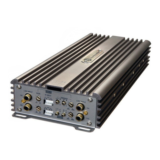
How to install and operate the
DLS amplifier models
CC-2
CC-4
CC-500
Contents
Features...............................................
Installation............................................
Routing Wires........................................
Tools and materials needed......................
Wiring & crossovers:
Power and remote wiring............................. 3-4
Low & High level input wiring ......................
Input level control, BASS EQ, etc ...............
Features on each model .............................
CC-500 speaker wiring:
One or more subwoofers............................... 6
Front speakers........................................
Subwoofer.............................................
Four speakers........................................
Two speakers and bridged subwoofer........
Two subwoofers or a stereo speaker pair
connected in bridge mode .........................
Testing................................................
Troubleshooting....................................
Professional tips...................................
Specifications.......................................
This product must be returned to the
separate collection system for electronic
products. Do not dispose this product
together with general household waste.
DLS amplifiers are designed and engineered by:
DLS Svenska AB
P.O. Box 13029 - SE-40251 Göteborg - Sweden
Tel: +46 31 840060 - Fax: +46 31 844021
E-mail: info@dls.se
www.dls.se
Sound tuned in England.
2
2
2
3
4
5
5
7
7
8
8
9
10
10
11
12
Advertisement
Table of Contents

Related Manuals for DLS CC-2


Summary of Contents for DLS CC-2
-
Page 1: Table Of Contents
Tools and materials needed………..... use of the above amplifiers. Wiring & crossovers: Your DLS amplifiers must be installed correctly in Power and remote wiring......3-4 order to work well. This manual will show you how Low & High level input wiring ...... -
Page 2: Features
The amplifier power terminals on CC-2 & CC-4 IMPORTANT! accept AWG 5 cables, so If possible buy AWG 5 = Use the metal screws coming with the amplifier 16 mm cable for best performance. -
Page 3: Tools And Materials Needed
Grease to protect the ground connection from oxidation Battery + pole DLS FH1 Material: fuse holder Speaker wire: minimum 12 AWG = 4 mm for subwoofers con- nected to CC-500 13 –... -
Page 4: Low & High Level Input Wiring
Most trunk-mount amplifiers need a 20 Black: To ground feet RCA cable ( appr 5 – 6 meters). Blue: CH3 - Connect to input socket CH1 / CH2 on CC-2. Yellow: CH3 + Or R/ L on CC-500. Hi level input plug. -
Page 5: Features On Each Model
Input Level control - GAIN Bass EQ / Bass boost CC-2 / CC-500 Bass EQ or Bass boost is used The GAIN control, MIN – MAX, to increase the bass volume at a matches the output of your radio specific frequency (60 Hz). - Page 6 CC-500 Speaker wiring CC-500 Two 4 ohm subwoofers One 4 ohm or 2 ohm subwoofer NOTE! NOTE! Subwoofer impedance can be 4 ohm or 2 ohm. Two 4 ohm subwoofers gives a 2 ohm load when Minimum amplifier load is 1 ohm, lower impedan- connected in this way.
-
Page 7: Speaker Wiring
CC-2 Speaker wiring CC-2 Two fullrange speakers to channel 1 / 2 One 4 ohm subwoofer bridged NOTE! Minimum speaker impedance in bridged connec- tion is 4 ohm, this connection gives a 2 ohm load NOTE! with a 4 ohm subwoofer (the load is halved when Minimum amplifier load is 2 ohm in stereo mode, connected in bridge mode). -
Page 8: Front Speakers
CC-4 Speaker wiring CC-4 1. Four fullrange speakers to CC-4. One pair 2. Two fullrange speakers and one subwoofer in front and one pair in rear. bridged to CC-4 (3-channel mode). Subwoofer Rear Front 4 ohm speakers speakers Front speakers Rear or front stereo speakers Front and rear stereo speakers connected to channels 1 / 2 and subwoofer... - Page 9 CC-4 Speaker wiring CC-4 3. Two subwoofers or stereo speakers brid- Filter settings front channels CH 1 / 2 ged to CC-4. Filter settings rear channels CH 3 / 4 The low pass filter is mostly used for sub- woofers. It will allow low frequencies only and blocks higher frequen- cies.
-
Page 10: Testing
4. Check the amplifier protection fuses. Are these broken change to new ones with the same value. If short circuiting continues, contact your local DLS dealer. A fault may exist in the amplifier. 5. To start the amplifier requires a remote voltage of Test power wiring 9-15 volt. -
Page 11: Professional Tips
If noise remains regardless of cable position, try to use so called Quasi-balanced signal NOTE! Tweeters can not be tested this way, dou- cables. DLS PRO-cables are Quasibalanced. ble check the connections instead. Professional Tip: Professional Tip: Installing in trunk... -
Page 12: Specifications
Power terminal size 2 AWG / 33 mm Speaker terminal size 7 AWG / 10 mm Weight 2,4 kg CC-2 CC-4 Number of channels Amplifier class Power output RMS in 4 ohm 2 x 110 W 4 x 50 W...
Need help?
Do you have a question about the CC-2 and is the answer not in the manual?
Questions and answers