Table of Contents
Advertisement
Quick Links
Welcome!
This owners manual is written in easy english and
uses a lot of drawings to simply the installation and
use of the above amplifiers.
Your DLS amplifiers must be installed correctly in
order to work well. This manual will show you how
to install the amplifier like a pro. Please read the
entire manual before beginning the installation.
Install the amplifier yourself if you feel confident
with our instructions and if you have the proper tools.
However if you feel unsure, turn over the installation
job to someone better suited to it.
Warranty Service
This amplifier is covered by warranty, depending on
the conditions in the country where it is sold. If the
amplifier is returned for service, please include the
original dated receipt with the product.
Technical Assistance
For technical assistance ask the shop where the
product was sold or the distributor in your very
country. Information can also be found on our WEB-
site www.dls.se
We follow a policy of continuous advancement in
development. For this reason all or part of specifica-
tions & designs may be changed without prior notice.
DECLARATION OF CONFORMITY
DLS amplifiers for vehicles are manufactured in
accordance with the EU directive EEC 95/54 (72/245/
EEC) and are marked with the approval number.
They are also marked in accordance with the WEEE-
directive 2002/96/EC.
The products are also produced in accordance with
the EU RoHS directive 2002/95/EC.
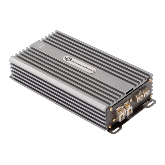
How to install and operate the
DLS amplifier models
CCi2 / CCi4
CCi44 / CCi44-40
CCi500 / CCi500-40
Contents
Features...............................................
Installation............................................
Routing Wires........................................
Tools and materials needed......................
Power and remote wiring............................. 3-4
Low & High level input wiring ......................
Input level control, BASS EQ, etc ...............
Features on each model .............................
CCi500 / CCI500-40 speaker wiring:
One or more subwoofers............................... 6
Front speakers........................................
Subwoofer.............................................
Four speakers........................................
Two subwoofers or a stereo speaker pair
connected in bridge mode .........................
Testing................................................
Troubleshooting....................................
Professional tips...................................
Specifications.......................................
This product must be returned to the
separate collection system for electronic
products. Do not dispose this product
together with general household waste.
DLS amplifiers are engineered by DLS Sweden,
a part of:
Winn Scandinavia AB
Elementvägen 15 - SE-702 27 Örebro - Sweden
Tel: +46 19 20 67 65 - E-mail: info@dls.se
www.dls.se
Sound tuned in England.
2
2
2
3
4
5
5
7
7
8
8
9
10
10
11
12
Advertisement
Table of Contents

Related Manuals for DLS CCi500-40


Summarization of Contents
Warranty and Technical Information
Warranty Service
Information regarding warranty coverage and return procedures for serviced amplifiers.
Technical Assistance
Guidance on obtaining technical support through dealers or the official website.
Declaration of Conformity
Details on compliance with EU directives for vehicle amplifiers.
Amplifier Installation and Wiring
Installation Guidelines
Instructions for choosing a mounting location and preparing for installation.
Disconnect Battery
Essential safety step to disconnect the battery's negative terminal before starting.
Routing Wires
Guidance on safely routing power, RCA, and speaker cables.
Power and Ground Connections
Tools and Material Needed
List of required tools and materials for installation.
Power Wiring
Instructions for connecting the main power supply with fuse holder.
Ground Terminal (GND)
Procedure for establishing a clean and secure ground connection.
Power and Protect Lights
Explanation of the amplifier's indicator lights.
Signal Input Wiring
Remote Terminal (REM)
Connecting the remote turn-on/off signal from the head unit.
High Level Input Wiring
Connecting the amplifier using speaker outputs from the head unit.
Low Level Input Wiring
Connecting the amplifier using RCA outputs from the head unit.
Amplifier Controls and Filters
Input Level Control (GAIN)
Adjusting input gain to match head unit output.
High Pass Filter (HPF)
Blocking low frequencies to protect speakers.
Low Pass Filter (LPF)
Allowing low frequencies for subwoofers.
Bass EQ and Subsonic Filter
Adjusting bass boost and filtering ultra-low frequencies.
Model-Specific Features
Overview of filters and features for CCi500, CCi2, and CCi4 models.
CCi500 / CCi500-40 Speaker Wiring and Settings
Speaker Wiring Configurations
Diagrams for connecting two 4-ohm subwoofers or one 4/2-ohm subwoofer.
Low Pass Filter Settings
Adjusting LPF for subwoofers and selecting slope.
Phase Switch Adjustment
Adjusting subwoofer phase for optimal sound staging.
Remote Sub Level Control
Connecting and using the external remote bass control.
CCi2 Speaker Wiring and Settings
CCi2 Speaker Wiring
Diagrams for connecting two full-range speakers or a bridged subwoofer.
Filter Settings for Stereo Use
Setting HPF for stereo speaker channels.
Filter Settings for Subwoofer Use
Setting LPF for subwoofer connection.
CCi4 / CCi44 / CCi44-40 Speaker Wiring and Settings
Speaker Wiring: Four Speakers
Connecting front and rear stereo speakers to channels 1/2 and 3/4.
Speaker Wiring: Bridged Subwoofer
Connecting front speakers to channels 1/2 and a subwoofer to channels 3/4.
Filter Settings for Front Channels
Setting HPF for front channels 1/2.
Filter Settings for Rear Channels
Setting LPF for rear channels 3/4.
CCi4 / CCi44 / CCi44-40 Bridged Wiring
Speaker Wiring: Two Bridged Speakers
Wiring diagram for two 4-ohm subwoofers or speakers bridged to CCi4/CCi44.
Filter Settings for Bridged Channels
Setting LPF for subwoofers and HPF for stereo speakers.
Troubleshooting and Testing
Troubleshooting Common Issues
Diagnosing amplifier problems like no power, fuse blowing, or overheating.
Testing Procedures
Steps to verify power wiring and speaker connections after installation.
Professional Tips and Best Practices
Noise Problems Solutions
Tips for eliminating engine whine and constant noise.
Speaker Polarity Check
Ensuring speakers are connected in phase for optimal sound.
Wire Management and Connections
Advice on securing wires, crimping, and separating signal from power wires.
Need help?
Do you have a question about the CCi500-40 and is the answer not in the manual?
Questions and answers