Table of Contents
Advertisement
How to install and
operate the
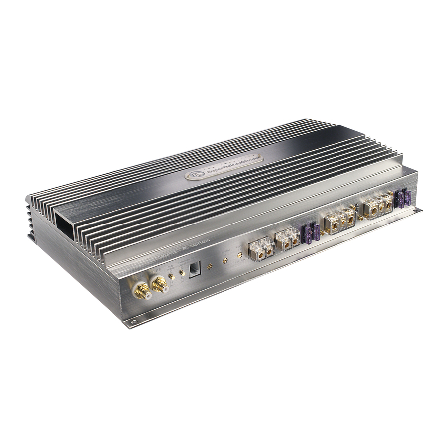
DLS ULTIMATE
A-series amplifiers
A1, A2, A3, A4, A5,
A6, A7 & A8
Welcome!
This owners manual is written in easy english and
uses a lot of drawings to simply the installation and
use of the above amplifiers.
Your DLS amplifier must be installed correctly in
order to work well. This manual will show you how
to install the amplifier like a pro. Please read the
entire manual before beginning the installation.
Install the amplifier yourself if you feel confident with
our instructions and if you have the proper tools.
However if you feel unsure, turn over the installa-
tion job to someone better suited to it.
Warranty Service
This amplifier is covered by warranty, depending
on the conditions in the country where it is sold. If
the amplifier is returned for service, please include
the original dated receipt with the product.
Technical Assistance
For technical assistance ask the shop where the product
was sold, or the distributor in your country.
You can always phone the DLS Helpdesk in Sweden
+ 46 31 84 00 60 or send an e-mail to info@dls.se.
Information can also be found on our WEB-site
www.dls.se
Contents
Caution.....................................
Installation................................
Tools and materials needed..........
Amplifier installation kit................
Routing Wires............................
Power terminals..........................
Inputs and controls......................
Input wiring...................................
Input level control..........................
Phase control................................
Remote bass level.........................
Protection circuits..........................
Input & controls A7.......................
Crossovers / filters.......................
Crossovers / filters A7....................
Professional tips............................
Wiring examples:
DLS A1 & A2.................................
DLS A3.........................................
DLS A4.........................................
DLS A5.........................................
DLS A6.........................................
DLS A7.........................................
DLS A8.........................................
Testing......................................
Trouble-shooting..........................
Specifications..............................
Approval of electromagnetic compatability
according to the EEC Directive 95/54/EC for
DLS A1, A2, A3, A4, A5, A6, A7 & A8.
E 11
Approval No: 10R-020962
2
2
3
3
3
4
5
5
5
5
5
5
6
7
8
9
10-11
12-13
14-16
17
18
19-22
23-24
25
25
26-27
Advertisement
Table of Contents

Related Manuals for DLS ULTIMATE A1


Summary of Contents for DLS ULTIMATE A1
-
Page 1: Table Of Contents
DLS A6... DLS A7... DLS A8... Testing……………………………….. Trouble-shooting…………………….. Specifications………………………... Approval of electromagnetic compatability according to the EEC Directive 95/54/EC for DLS A1, A2, A3, A4, A5, A6, A7 & A8. E 11 Approval No: 10R-020962 10-11 12-13 14-16 19-22 23-24... -
Page 2: Caution
These are the minimum sizes of power cables we recommend for the different models: Cable length:< 1,5 m 1,5 - 4 m A1/A2 10 mm 16 mm A3 / A4 / A5 16 mm 21 mm... -
Page 3: Tools And Materials Needed
Tools and material needed Tools: Flat and Phillips screwdrivers Wire cutter Wire stripper Electric drill with drills Crimping tool Digital multimeter or test lamp Wire brush, scraper or a piece of an abrasive sheet to remove paint for a good ground connection Grease to protect the ground connection from oxidation Material:... -
Page 4: Wiring
Wiring Power, remote and fan terminals Power terminal for A1, A2, A5, A7, A8 Connect the fuse holder as close to the vehicle battery + as possible, using AWG 5 = 16 mm (see table on page 2). Use ring crimp terminal cable to connect to battery +. -
Page 5: Protection Circuits
12 feet ( 2 – 3 meters) RCA cables. Avoid placing the RCA cable close to spea- ker cables, power cables and remote control cable. DLS A1, A2 and A3 uses a single pair of RCA inputs while three and four channels... - Page 6 Input and controls A7 FRONT SPEAKERS HP-filter LEVEL +LEFT- +RIGHT- 3,5V 80 400 7V 0,2V x20 change by bottom switch Input Wiring DLS A7 has a more sofisticated input configuration and can be connected in different ways which are described here.
-
Page 7: Crossovers / Filters
2-way speakersystem. Crossovers on each model DLS A1 DLS A1 has an internal adjustable HP-filter that can be switched in/out. It can be set from 20 up to 200 Hz. It also has an internal fixed LP-filter that can be set to either 70 or 90 Hz. - Page 8 HP-filter FRONT SPEAKERS LEVEL +LEFT- +RIGHT- 3,5V 80 400 7V 0,2V x20 change by bottom switch Crossovers / filters on A7 DLS A7 amplifier include highpass filter (HP), lowpass filter (LP). On the two front channels the HP- filter can be switched between two different frequency ranges, likewise for the LP-filter on the rear channels.
-
Page 9: Noise Problems
Professional Tip: NOISE PROBLEMS WHINING NOISE VARYING WITH ENGINE REVOLUTIONS: Do this: Rewire the power supply (12 V) to source unit direct from battery. Rewire ground wire from source unit to clean position on chassis. Check all power connections to ensure that they are clean and tight. - Page 10 The main difference between DLS A1 and A2 is the lowpass filter and the power output. A1 has a 3-way filter selector under the bottom plate and A2 has a continously variable filter on the front.
-
Page 11: Bridge Mode
LEVEL HP-filter LEFT RIGHT 20 200 7,0V Pre out 1 107,3 Remote For power cable, speaker cable and fuse size selection we refer to page 4. DLS A1 HP-filter LEVEL 3,5V 7,0V 0,2V 20 200 SPEAKERS LEVEL +LEFT- +RIGHT- 3,5V... - Page 12 Power capacitor as in the example. DLS A3 can be connected in different ways: 1. As a stereo amplifier connected with a speaker system of coaxial, 2-way or 3-way type. Two speaker systems can be connected in parallel, one front and one rear system.
- Page 13 1 107,3 Use a 2 mm hexagon key to speaker terminals. Use a 2,5 mm hexagon key to DC input termin- als on A1 Use a 4 mm hexagon key to DC input terminals on A2, A3, A4 DC - FEED DLS A3...
- Page 14 Power Fan 12 V capacitor Use a 2 mm hexagon key to speaker terminals. Use a 2,5 mm hexagon key to DC input terminals on A1 Use a 4 mm hexagon key to DC input terminals on A2, A3, A4...
- Page 15 20 200 20 200 Use a 2 mm hexagon key to speaker terminals. Use a 2,5 mm hexagon key to DC input terminals on A1 Use a 4 mm hexagon key to DC input terminals on A2, A3, A4 ULTIMATE A4...
- Page 16 20 200 Button in Use a 2 mm hexagon key to speaker terminals. Use a 2,5 mm hexagon key to DC input terminals on A1 Use a 4 mm hexagon key to DC input terminals on A2, A3, A4 ULTIMATE A4...
- Page 17 WIRING EXAMPLES A5 Connection of a front system in stereo and a subwoofer in mono. DC - FEED DLS A5 POWER IN FUSES 30 A x 3 BATT+ REM GND Fuse 100 A Battery 12 volt HP-filter setting: 80 Hz Button in REAR SPEAKERS LEVEL...
- Page 18 WIRING EXAMPLES A6 Connection of two 4 ohm subwoofers You can use all DLS subwoofers in this example. All speakers must be 2-4 ohm. If you have subwoofer with dual voice coils, connect one voice coil to each output terminal. For power cable, speaker cable and fuse size selection we refer to page 2.
- Page 19 WIRING EXAMPLES A7 Example 1: Speaker wiring with front speakers, rear speakers and one or more subwoofers HP-filter: 80 Hz Button in FRONT SPEAKERS HP-filter LEVEL +LEFT- +RIGHT- 3,5V 80 400 7V 0,2V x20 change by bottom switch DC - FEED DLS A7 For DC-feed, see page 4 If you have problems with the mid bass driver ”reaching the bottom”...
- Page 20 WIRING EXAMPLES A7 Example 2: Speaker wiring with active crossover to a front speaker system and one or more subwoofers HP-filter setting: 4 kHz Button in HP-filter FRONT SPEAKERS LEVEL +LEFT- +RIGHT- 3,5V 80 400 7V 0,2V x20 change by bottom switch Pre out front Tweeters with active high-pass...
- Page 21 WIRING EXAMPLES A7 Example 3: System with front speaker system, rear fill speakers and one or more subwoofers Highpass filter 80 Hz Button in FRONT SPEAKERS HP-filter LEVEL +LEFT- +RIGHT- 3,5V 80 400 7V 0,2V x20 change by bottom switch Filter Filter Two-way front system...
- Page 22 WIRING EXAMPLES A7 Example 4: Speaker wiring with acive/passive crossover to a 3-way front speaker system and one or more subwoofers HP-filter setting: 400 Hz Button in HP-filter FRONT SPEAKERS LEVEL +LEFT- +RIGHT- 3,5V 80 400 7V 0,2V x20 change by bottom switch Filter Filter...
- Page 23 WIRING EXAMPLES A8 Example 1: Speaker wiring with front and rear speakers LP-filter not in use Button Out FRONT SPEAKERS LEVEL +LEFT- +RIGHT- 5V 0,5V HP-filter change by bottom switch Use one RCA cable with Y-split, or two separate RCA-cables for signal from head unit to amplifier.
- Page 24 WIRING EXAMPLES A8 Example 2: Speaker wiring with subwoofers in bridge mode to both front and rear channels LP-filter setting: 70 - 80 Hz. Button in FRONT SPEAKERS LEVEL LP-filter +LEFT- +RIGHT- 50 125 5V 0,5V HP-filter change by bottom switch Pre out front Subwoofer...
-
Page 25: Testing
Testing Before you finish the installation, you should do the following tests to make sure the wiring is correct and everything is operating properly. Reconnect Battery When wiring is complete, reconnect the battery negative terminal. Test power wiring Turn on the head unit but do not turn up the volume. -
Page 26: Specifications
SPECIFICATIONS A1 to A6 Model Number of channels Working mode Power output at 13,8 Volt, 20 Hz - 20 kHz, THD max 0,1%: RMS power output in 4 ohm 2 x 45 W RMS power output in 2 ohm 2 x 80 W... -
Page 27: Specifications A7 & A8
SPECIFICATIONS A7 & A8 Model RMS output per channel at 13,8 volts, 20 Hz - 20 kHz , < 0,1% distortion. Front and rear channels: Power output in 4 ohm Power output in 2 ohm Power output in bridge mode Subchannel: Power output in4 ohm Power output in 2 ohm... - Page 28 DLS Svenska AB P.O. Box 13029 S-40251 Göteborg, Sweden Tel: +46 31 840060 Fax: +46 31 844021 E-mail: info@dls.se www.dls.se...
Need help?
Do you have a question about the ULTIMATE A1 and is the answer not in the manual?
Questions and answers