Table of Contents
Advertisement
Quick Links
Welcome!
This owners manual is written in easy english and
uses a lot of drawings to simply the installation and
use of the above amplifiers.
Your DLS amplifiers must be installed correctly in
order to work well. This manual will show you how
to install the amplifier like a pro. Please read the
entire manual before beginning the installation.
Install the amplifier yourself if you feel confident
with our instructions and if you have the proper tools.
However if you feel unsure, turn over the installation
job to someone better suited to it.
Warranty Service
This amplifier is covered by warranty, depending on
the conditions in the country where it is sold. If the
amplifier is returned for service, please include the
original dated receipt with the product.
Technical Assistance
For technical assistance ask the shop where the
product was sold or the distributor in your very
country. Information can also be found on our WEB-
site www.dls.se
We follow a policy of continuous advancement in
development. For this reason all or part of specifica-
tions & designs may be changed without prior notice.
DECLARATION OF CONFORMITY
DLS amplifiers for vehicles are manufactured in
accordance with the EU directive EEC 95/54 (72/245/
EEC) and are marked with the approval number.
They are also marked in accordance with the WEEE-
directive 2002/96/EC.
The products are also produced in accordance with
the EU RoHS directive 2002/95/EC.
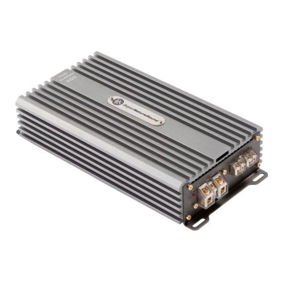
How to install and operate the
DLS amplifier models
CCi2 / CCi4
CCi44 / CCi44-40
CCi500 / CCi500-40
Contents
Features...............................................
Installation............................................
Routing Wires........................................
Tools and materials needed......................
Power and remote wiring............................. 3-4
Low & High level input wiring ......................
Input level control, BASS EQ, etc ...............
Features on each model .............................
CCi500 / CCI500-40 speaker wiring:
One or more subwoofers............................... 6
Front speakers........................................
Subwoofer.............................................
Four speakers........................................
Two subwoofers or a stereo speaker pair
connected in bridge mode .........................
Testing................................................
Troubleshooting....................................
Professional tips...................................
Specifications.......................................
This product must be returned to the
separate collection system for electronic
products. Do not dispose this product
together with general household waste.
DLS amplifiers are engineered by DLS Sweden,
a part of:
Winn Scandinavia AB
Elementvägen 15 - SE-702 27 Örebro - Sweden
Tel: +46 19 20 67 65 - E-mail: info@dls.se
www.dls.se
Sound tuned in England.
2
2
2
3
4
5
5
7
7
8
8
9
10
10
11
12
Advertisement
Table of Contents

Related Manuals for DLS CCi500


Summarization of Contents
Installation
Before you begin installation
Preparation steps before installing the amplifier.
Amplifier location
Guidance on selecting an appropriate place to mount the amplifier.
Disconnect Battery
Instruction to disconnect the vehicle battery prior to installation.
Power wiring
Power terminal (+12V)
Instructions for connecting the main power supply to the amplifier.
Ground Terminal (GND)
Guidance on establishing a proper chassis ground connection.
Power Light / Protect light
Explanation of the amplifier's indicator lights.
Low level Input Wiring
Low level input
Details on connecting RCA cables for audio input.
High Level Input wiring
CCi500 / CCi500-40 / CCi2
Wiring example for high level input on specific models.
CCi4 / CCi44 / CCi44-40
Wiring example for high level input on 4-channel models.
Speaker wiring CCi500 / CCi500-40
Two 4 ohm subwoofers
Wiring diagram for connecting two 4-ohm subwoofers.
One 4 ohm or 2 ohm subwoofer
Wiring diagram for a single 4-ohm or 2-ohm subwoofer.
Speaker wiring CCi2
Two fullrange speakers to channel 1/2
Wiring diagram for two full-range speakers.
One 4 ohm subwoofer bridged
Wiring diagram for a 4-ohm subwoofer bridged to channel 1/2.
Speaker wiring CCi4 / CCi44 / CCi44-40
1. Four fullrange speakers. One pair in front and one pair in rear.
Wiring for four full-range speakers across front and rear channels.
2. Two fullrange speakers and one subwoofer bridged to CCi4 / CCi44 (3-channel mode).
Wiring for two speakers and a bridged subwoofer.
Speaker wiring CCi4 / CCi44 / CCi44-40
3. Two subwoofers or stereo speakers bridged to CCi4 / CCi44.
Wiring for two subwoofers or stereo speakers in bridged mode.
Troubleshooting
THE AMPLIFIER IS DEAD
Steps to diagnose a completely non-functional amplifier.
AMPLIFIER PROTECTION FUSE BLOWS AT LOW VOLUME
Troubleshooting steps for blown protection fuses at low volume.
THE AMPLIFIER TURNS OFF AFTER 10 - 30 MINUTES
Diagnosing amplifier shutdown due to overheating or impedance.
NO OUTPUT FROM ONE OR MORE SPEAKERS
Steps to identify issues with speaker output.
Testing
Reconnect Battery
Instruction to reconnect the battery after wiring is complete.
Test power wiring
Procedure to test the amplifier's power connections.
Test speaker connections
Procedure to verify speaker wiring and connections.
Professional Tip
NOISE PROBLEMS
Troubleshooting advice for engine-related noise issues.
CONSTANT WHINING NOISE
Steps to resolve continuous whining noise in the audio system.
SPEAKER POLARITY CHECK
Guide to checking and ensuring correct speaker phasing.
Installing in trunk
Advice on routing wires and installing the amplifier in the trunk.
Securing wires
Tips on using wire ties to bundle cables safely.
Crimp connections
Instructions for making secure crimp connections.
Speaker and power wires
Guidance on separating speaker and power wires to prevent noise.
Need help?
Do you have a question about the CCi500 and is the answer not in the manual?
Questions and answers