Table of Contents
Advertisement
Quick Links
Welcome!
This owners manual is written in easy english and
uses a lot of drawings to simply the installation and
use of the above amplifiers.
Your DLS amplifiers must be installed correctly in
order to work well. This manual will show you how
to install the amplifier like a pro. Please read the
entire manual before beginning the installation.
Install the amplifier yourself if you feel confident
with our instructions and if you have the proper tools.
However if you feel unsure, turn over the installation
job to someone better suited to it.
Warranty Service
This amplifier is covered by warranty, depending on
the conditions in the country where it is sold. If the
amplifier is returned for service, please include the
original dated receipt with the product.
Technical Assistance
For technical assistance ask the shop where the
product was sold or the distributor in your very
country. Information can also be found on our WEB-
site www.dls.se
We follow a policy of continuous advancement in
development. For this reason all or part of specifica-
tions & designs may be changed without prior notice.
DECLARATION OF CONFORMITY
DLS amplifiers for vehicles are manufactured in
accordance with the EU directive EEC 95/54 (72/245/
EEC) and are marked with the approval number.
They are also marked in accordance with the WEEE-
directive 2002/96/EC.
The products are also produced in accordance with
the EU RoHS directive 2002/95/EC.
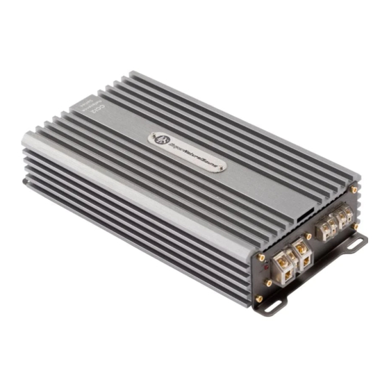
How to install and operate the
DLS amplifier models
CCi2 / CCi4
CCi44 / CCi44-40
CCi500 / CCi500-40
Contents
Features...............................................
Installation............................................
Routing Wires........................................
Tools and materials needed......................
Power and remote wiring............................. 3-4
Low & High level input wiring ......................
Input level control, BASS EQ, etc ...............
Features on each model .............................
CCi500 / CCI500-40 speaker wiring:
One or more subwoofers............................... 6
Front speakers........................................
Subwoofer.............................................
Four speakers........................................
Two subwoofers or a stereo speaker pair
connected in bridge mode .........................
Testing................................................
Troubleshooting....................................
Professional tips...................................
Specifications.......................................
This product must be returned to the
separate collection system for electronic
products. Do not dispose this product
together with general household waste.
DLS amplifiers are engineered by DLS Sweden,
a part of:
Winn Scandinavia AB
Elementvägen 15 - SE-702 27 Örebro - Sweden
Tel: +46 19 20 67 65 - E-mail: info@dls.se
www.dls.se
Sound tuned in England.
2
2
2
3
4
5
5
7
7
8
8
9
10
10
11
12
Advertisement
Table of Contents

Related Manuals for DLS CCi44


Summarization of Contents
Installation
Amplifier Location
Guidance on selecting a suitable location for the amplifier, considering heat and air circulation.
Disconnect Battery
Essential safety step: always disconnect the negative battery terminal before starting installation.
Routing Wires
Professional Tip: Power Cable Gauge
Guidance on selecting appropriate power cable gauge for optimal sound and future expansion.
Power Wiring
Power Terminal (+12V)
Instructions for connecting the +12V power terminal, including fuse holder placement.
Ground Terminal (GND)
Guidance on establishing a clean and secure chassis ground connection for the amplifier.
Indicator Lights
Explanation of the green power and red protect indicator lights on the amplifier.
Remote Terminal (REM)
Remote Connection for RCA Input
How to connect the remote turn-on/off signal from the car stereo via RCA cable.
Alternative Remote Connection
Connecting the remote signal to the ignition key or accessories fuse when no stereo output is available.
Automatic Start with High Level Input
Note that the amplifier starts automatically when using high-level input.
High Level Input Wiring
High Level Input General
Using speaker output signal from the head unit when RCA outputs are unavailable.
High Level Input for CCi500/CCi500-40/CCi2
Wiring diagram for high-level input on CCi500/CCi500-40 and CCi2 models.
High Level Input for CCi4/CCi44/CCi44-40
Wiring for the four-channel CCi4/CCi44/CCi44-40 using high-level input.
Low Level Input Wiring
Low Level Input Description
Using shielded RCA cables for the best sound quality, typically 20 feet.
Low Level Input for CCi4/CCi44/CCi44-40
Connecting CCi4/CCi44/CCi44-40 using separate RCA cables or a Y-split.
Speaker Wiring CCi500 / CCi500-40
Two 4 ohm Subwoofers
Wiring configuration for connecting two 4 ohm subwoofers to the amplifier.
One 4 ohm or 2 ohm Subwoofer
Wiring configuration for connecting a single 4 ohm or 2 ohm subwoofer.
Filter Settings Low Pass Filter
Details on the low pass filter settings and selectable slopes for subwoofers.
Phase Switch
Guidance on adjusting the phase switch for optimal front stage imaging with subwoofers.
Remote Sub Level Control
Instructions for connecting and using the external remote sub level control box.
Speaker Wiring CCi2
Two Fullrange Speakers to Channel 1/2
Wiring diagram for connecting two fullrange speakers to channels 1 and 2.
One 4 ohm Subwoofer Bridged
Wiring diagram for connecting a 4 ohm subwoofer in bridged mode.
Filter Settings CH 1/2 for 2-channel Stereo Use
High pass filter settings for stereo use on channels 1 and 2.
Filter Settings CH 1/2 for Subwoofer Use
Low pass filter settings for subwoofer use on channels 1 and 2.
Speaker Wiring CCi4 / CCi44 / CCi44-40
1. Four Fullrange Speakers
Connecting front and rear stereo speakers to respective channels.
2. Two Fullrange Speakers and One Subwoofer Bridged
Connecting two fullrange speakers and a subwoofer in bridged mode.
Filter Settings Front Channels CH 1/2
High pass filter settings for front channels 1 and 2, used for fullrange speakers.
Filter Settings Rear Channels CH 3/4
High pass filter settings for rear channels 3 and 4, used for fullrange speakers.
Speaker Wiring CCi4 / CCi44 / CCi44-40 (Continued)
3. Two Subwoofers or Stereo Speakers Bridged
Connecting two subwoofers or stereo speakers in bridged mode.
Filter Settings Front Channels CH 1/2
Low pass filter settings for channels 1/2 when used for subwoofers.
Filter Settings Rear Channels CH 3/4
High pass filter settings for channels 3/4 when used for bridging stereo speakers.
Troubleshooting
The Amplifier Is Dead
Steps to diagnose and resolve issues when the amplifier shows no power.
Amplifier Protection Fuse Blows at Low Volume
Troubleshooting steps for when protection fuses blow even at low volume levels.
The Amplifier Turns Off After 10-30 Minutes
Diagnosing overheating issues due to inadequate ventilation or impedance.
No Output From One or More Speakers
Steps to identify and fix issues with a single speaker or channel not producing sound.
Testing
Reconnect Battery
Instruction to reconnect the battery negative terminal after wiring is complete.
Test Power Wiring
Procedure to test power connections and ensure the amplifier turns on correctly.
Test Speaker Connections
Verifying speaker wiring and ensuring all speakers operate properly.
Professional Tips
Noise Problems: Whining Noise Varying with Engine Revolutions
Steps to diagnose and eliminate engine-speed-related whining noise.
Noise Problems: Constant Whining Noise
Troubleshooting steps for persistent constant whining noise issues.
Speaker Polarity Check
Guide on checking speaker polarity to ensure proper phase alignment and sound quality.
Installing in Trunk
Advice on running wires and mounting the amplifier when installing in the car trunk.
Securing Wires
Tips on using wire ties to bundle cables neatly and safely.
Crimp Connections
Step-by-step guide for making secure crimp connections for wiring.
Speaker and Power Wires
Guidance on routing speaker and power wires separately to prevent interference.
Need help?
Do you have a question about the CCi44 and is the answer not in the manual?
Questions and answers