
Related Manuals for JBL Bass2/Basswave


Summary of Contents for JBL Bass2/Basswave
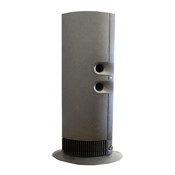
- Page 1 Bass2/Basswave Powered Subwoofer TECHNICAL MANUAL JBL Consumer Products Inc. 80 Crossways Park West Woodbury, N.Y. 11797 1-800-336-4JBL in the USA A Harman International Company Part No.: 1112-BASS2/BASSWAVE...
-
Page 2: Table Of Contents
Line level and speaker level inputs. * Early versions of the Bass2/Basswave will cycle into a standby mode when the signal source is absent after a predetermined time; the green LED turns OFF when this happens on the 120 volt version, the LED cycles to RED on the 230 volt version. -
Page 3: Disassembly Procedures
For this reason, the Bass2/Basswave Subwoofer may differ in some respect from its published specifications and descriptions, but will always equal or exceed the... -
Page 4: Bass2/Basswave Exploded View
Powered Subwoofer BASS2/BASSWAVE BASS2/BASSWAVE EXPLODED VIEW... -
Page 5: Test Procedure
Powered Subwoofer BASS2/BASSWAVE TEST PROCEDURES Equipment needed: buzzes or any other noises. If any unusual noises are heard, remove driver and test. Functional/signal generator True RMS Multimeter Driver Function Integrated amplifier 1. Follow instructions on page 2 (“To Access Lower Cables - line level (RCA) and speaker cables Woofer”). -
Page 6: Wiring Diagram
1. Remove jumper wire JW12. WIRING DIAGRAM 2. Change resistor R24 to a 22k ohm, 5%, 1/8W. (JBL part# HM185-02202-00). 3. Change capacitor C19 to a .0047 uf cap. (JBL part# 3679472120). 4. Cut trace at SW1 (middle pin which runs to JW12). -
Page 7: Parts Lists
Powered Subwoofer BASS2/BASSWAVE BASS2/BASSWAVE PARTS LIST ELECTRICAL PARTS LIST Ref. Number Part Number Description Quantity R12, 13, 16, 17 307972-001 MF, 511-OHM, 1%, 1/2W Ref. Number Part Number Description Quantity 282822-001 MF, 12.1-OHM, 1%, 1/4W Capacitors 282833-001 MF, 16.5Ω, 1%, 1/4W HM14-0682 0.022µf, 5%, 50V... -
Page 8: Integrated Circuit Diagrams
Powered Subwoofer BASS2/BASSWAVE INTEGRATED CIRCUIT DIAGRAMS U1 - TL074 OP AMP (1/4 SHOWN) OUTPUT 1 OUTPUT 4 -INPUT 1 -INPUT 4 +INPUT 1 +INPUT 4 -INPUT +INPUT OUTPUT +INPUT 2 +INPUT 3 -INPUT 2 -INPUT 3 OUTPUT 2 OUTPUT 3... -
Page 9: Schematic Diagrams
Bass2/Basswave POWERED SUBWOOFER Bass2/Basswave Schematic Diagram TL074 +40V +15V +40V +15V -40V -15V R46 IS REPLACED BY 22 GA JUMPER WIRE FOR -40V -004, -005 & -006 ASSY. FOR -001, -002, -004 & CR10 -005 : 430 OHM +15V FOR -003, & -006 : 2K OHM. -
Page 10: Pot-Sub Board For 230V Versions 2
R46 IS REPLACED BY 22 GA JUMPER WIRE FOR -004, -005 & -006 ASSY. FOR -001, -002, -004 & -005 : 430 OHM FOR -003, & -006 : 2K OHM. JW13 EACH END TO P4 AND P5 ON POT-SUB BOARD FOR 230V VERSIONS (-002 &...
Need help?
Do you have a question about the Bass2/Basswave and is the answer not in the manual?
Questions and answers