JBL BassPro Service Manual
Hide thumbs
Also See for BassPro:
- Quick start manual (38 pages) ,
- Service manual (10 pages) ,
- Owner's manual (9 pages)

Related Manuals for JBL BassPro


Summary of Contents for JBL BassPro
- Page 1 BassPro Powered Subwoofer SERVICE MANUAL JBL Consumer Products 250 Crossways Park Dr. Woodbury, New York 11797 Rev0 5/2003...
- Page 2 CONTENTS SPECIFICATIONS ..........1 DETAILED SPECIFICATIONS.
-
Page 3: Specifications
BASSPRO AUTO SUBWOOFER SPECIFICATIONS GENERAL CONDITIONS: TEST INPUT SIGNAL FOR LINE IN – 2CH/60Hz/250mV. TEST OUTPUT – 1 W ATT 4 Ohms LOAD (Bridge). POWER SOURCE DC14.4V/12A min TEST CONDITIONS: ALL TEST SIGNALS FROM LINE IN UNLESS OTHER REMARKS. CROSSOVER VR AT MAX POSITION UNLESS OTHER REMARKS. -
Page 4: Connections
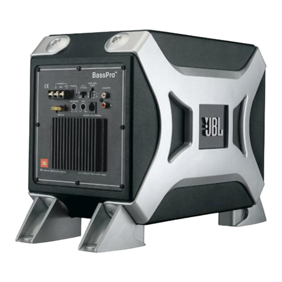
Figure 7. Please observe Positive Battery (BATT +12) and Ground met in the vehicle’s firewall. If a factory a +5 to +12 Vdc signal for BassPro the following installation tips: grommet is not available, install one. to turn on when using the line-level ( ) connections. - Page 5 BassPro APPLICATIONS Connection Panel BassPro is equipped with two line- Subwoofer Level Control level (RCA) inputs and two high-level inputs. To help you plan the installation of BassPro, we have included two system application diagrams in Figures 8 and 9. For more installation...
-
Page 6: Controls & Functions
AUTO TURN-ON: For speaker- 3. Turn the head unit ON and play a that help simplify sonic integration with will glow red when the BassPro is level connections, used this switch to selection of your favorite music almost any vehicle’s unique acoustic operating. - Page 7 Feed between the RJ11 receptacle on the UNDER-DASH MOUNTING the Subwoofer Level Control’s BassPro and the receptacle on the Select a mounting location that allows potentiometer shaft (with the knob Subwoofer Level Control (Figure 6).
-
Page 8: Troubleshooting
1. Inputs are not connected. Check connections. 2. Head-unit fader controls are not set properly. Adjust head-unit controls to feed audio signals to BassPro. 3. Incorrect GAIN control setting. Output sounds muddy or distorted. 1. GAIN is set too high. -
Page 9: Exploded View
BASS PRO EXPLODED VIEW Ref. Description Part Number Enclosure 241-060-00587 Side Baffles 301-ABS-00353 Logo 316-ABS-00538 Port Tube 249-ABS-00148 Right Bracket 325-ABS-00421 Left Bracket 325-ABS-00420 Plug (Screw Cap) 338-ABS-00126 Screw 351-FM04039A572 Screw 352-HM04014D611 16PF11BZW-AW01 Woofer (DCR = 3.6Ω x 4) Screw 325-FM04018A576 Amplifier Not For Sale... -
Page 14: Electrical Parts List
BassPro Electrical Parts List PART NO. DESCRIPTION REFERENCE DESIGNATOR Semiconductors 190-06m4558l I.C. NJRC NJM4558L Dual Op-Amp 190-14m13700n I.C. NS LM13700 Dual Op-Amp IC301 190-16a73770 I.C. TDA7377 Power Amp IC101,121 192-027c1815gr Transistor 2SC1815GR NPN Q31,40,301 192-028a1015gr Transistor 2SA1015GR PNP Q32,41,42 195-10204hd... - Page 15 PART NO. DESCRIPTION REFERENCE DESIGNATOR 135-3475m50 Electrolytic Cap. 4.7U 50V ±20% C304 135-3476m50 Electrolytic Cap. 47U 50V ±20% C41,102,123 135-4338m25 Electrolytic Cap. 3300U 25V ±20% Miscellaneous 120-12101k3 Inductor 100UH 1/2W 122-14050k4160 Inductor Ferrite 5uH 15A CR630*5R0KUM 154-k020a800 Fuse 20A 32V ATC UL/CSA 155-9f30240 Fuse Holder F30240100P 162-a040d001...
Need help?
Do you have a question about the BassPro and is the answer not in the manual?
Questions and answers