Table of Contents
Advertisement
Advertisement
Table of Contents

Related Manuals for Super X9SCi-LN4


Summary of Contents for Super X9SCi-LN4
- Page 1 X9SCi-LN4 X9SCi-LN4F X9SCA X9SCA-F USER’S MANUAL Revision 1.1...
- Page 2 Manual Revision 1.1 Release Date: February 6, 2013 Unless you request and receive written permission from Super Micro Computer, Inc., you may not copy any part of this document. Information in this document is subject to change without notice. Other products and companies referred to herein are trademarks or registered trademarks of their respective companies or mark holders.
-
Page 3: About This Motherboard
X9SCi-LN4/X9SCi-LN4F/X9SCA/X9SCA-F supports a single Intel® Xeon E3-1200 series, 2nd generation Intel Core® i3, Pentium®, Celeron® proces- sor in an LGA 1155 socket. With the Intel® C204 chipset built in, the X9SCi-LN4/ X9SCA series motherboard offers substantial enhancement in system performance and storage capability for next generation high end server platforms* in a sleek package. -
Page 4: Conventions Used In The Manual
X9SCi-LN4/X9SCi-LN4F/X9SCA/X9SCA-F Conventions Used in the Manual: Special attention should be given to the following symbols for proper installation and to prevent damage done to the components or injury to yourself: Danger/Caution: Instructions to be strictly followed to prevent catastrophic system failure or to avoid bodily injury Warning: Critical information to prevent damage to the components or data loss. -
Page 5: Contacting Supermicro
Contacting Supermicro Contacting Supermicro Headquarters Address: Super Micro Computer, Inc. 980 Rock Ave. San Jose, CA 95131 U.S.A. Tel: +1 (408) 503-8000 Fax: +1 (408) 503-8008 Email: marketing@supermicro.com (General Information) support@supermicro.com (Technical Support) Web Site: www.supermicro.com Europe Address: Super Micro Computer B.V. -
Page 6: Table Of Contents
System Resource Alert ................. 1-12 ACPI Features ....................1-13 Slow Blinking LED for Suspend-State Indicator ........... 1-13 Power Supply ....................1-13 Super I/O ....................... 1-14 Overview of the Nuvoton WPCM450 Controller ........... 1-14 Chapter 2 Installation Static-Sensitive Devices .................. 2-1 Precautions ..................... - Page 7 Table of Contents Memory Population Guidelines ..............2-11 Motherboard Installation ................2-13 Tools Needed ....................2-13 Location of Mounting Holes ................2-13 Installing the Motherboard ................2-14 Connectors/IO Ports ..................2-15 Motherboard I/O Backpanel ................2-15 ATX PS/2 Keyboard/Mouse Ports ............2-16 Universal Serial Bus (USB) ..............
- Page 8 X9SCi-LN4/X9SCi-LN4F/X9SCA/X9SCA-F CMOS Clear (JBT1) ................. 2-33 PCI Slot SMB Enable (JI C1/JI C2) ............2-33 VGA Enable (JPG1) ................. 2-34 Watch Dog Enable (JWD) ................ 2-34 USB Wake-Up (JPUSB1) ................. 2-35 BMC Enable (JPB) ................... 2-35 Onboard Indicators ..................2-36 LAN Port LEDs ..................
- Page 9 Table of Contents 4-3 Advanced Setup Configurations..............4-4 BOOT Feature ....................4-4 Quiet Boot ....................4-4 AddOn ROM Display Mode ................ 4-4 Bootup Num-Lock ..................4-4 Wait For 'F1' If Error ................... 4-4 Interrupt 19 Capture ................... 4-4 Watch Dog Function ................... 4-5 Power Button Function ................
- Page 10 X9SCi-LN4/X9SCi-LN4F/X9SCA/X9SCA-F Detect Non-Compliant Device ..............4-8 South Bridge Configuration ..............4-8 USB Functionst ..................4-8 Legacy USB Support .................. 4-9 BIOS EHCI Hand-Off.................. 4-9 IDE/SATA Configuration ................4-9 SATA Mode ....................4-9 IDE Mode ....................4-9 Serial-ATA Controller 0~1 ................4-9 SATA Port0~Port5 ..................
- Page 11 Table of Contents Event Logs ....................4-15 Smbios Event Log ..................4-15 Erase Event Log ..................4-15 When Log is Full ..................4-15 MECI ......................4-15 METW ....................... 4-15 4-5 IPMI Configuration (X9SCi-LN4F, X9SCA-F Only) ........4-16 BMC Support .................... 4-16 Wait For BMC ................... 4-16 BMC Self Test Log.................
- Page 12 X9SCi-LN4/X9SCi-LN4F/X9SCA/X9SCA-F Appendix B Software Installation Instructions Installing Drivers ....................B-1 B-2 Configuring SuperDoctor ® III ................B-2 Appendix C UEFI BIOS Recovery Instructions An Overview to the UEFI BIOS ..................C-1 How to Recover the UEFI BIOS Image (-the Main BIOS Block) .......C-1 To Recover the Main BIOS Block Using a USB-Attached Device ......C-1...
-
Page 13: Chapter 1 Introduction
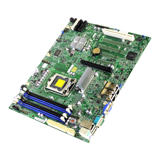
Chapter 1: Introduction Chapter 1 Introduction Overview Checklist Congratulations on purchasing your computer motherboard from an acknowledged leader in the industry. Supermicro boards are designed with the utmost attention to detail to provide you with the highest standards in quality and performance. Please check that the following items have all been included with your motherboard. - Page 14 X9SCi-LN4/X9SCi-LN4F/X9SCA/X9SCA-F X9SCA Series Motherboard Image Note: All graphics shown in this manual were based upon the latest PCB Revision available at the time of publishing of the manual. The motherboard you've received may or may not look exactly the same as the graphics...
- Page 15 Chapter 1: Introduction X9SCi-LN4 Series Motherboard Image Note: All graphics shown in this manual were based upon the latest PCB Revision available at the time of publishing of the manual. The motherboard you've received may or may not look exactly the same as the graphics...
- Page 16 X9SCi-LN4/X9SCi-LN4F/X9SCA/X9SCA-F Motherboard Layout (X9SCA Series) Important Notes to the User • See Chapter 2 for detailed information on jumpers, I/O ports and JF1 front panel connections. • " " indicates the location of "Pin 1". • Jumpers not indicated are for testing only.
- Page 17 Chapter 1: Introduction Motherboard Layout (X9SCi-LN4 Series) Important Notes to the User • See Chapter 2 for detailed information on jumpers, I/O ports and JF1 front panel connections. • " " indicates the location of "Pin 1". • Jumpers not indicated are for testing only.
- Page 18 JPG1 Onboard VGA Enable Pins 1-2 (Enabled) JPL1/JPL2 LAN1/LAN2 Enable Pins 1-2 (Enabled) JPL3/JPL4 LAN3/LAN4 Enable (X9SCi-LN4/-LN4F only) Pins 1-2 (Enabled) JPUSB1 Backpanel USB 0/1 Wake-Up Enable Pins 1-2 (Enabled) Watch Dog Timer Enable Pins 1-2 (Reset) X9SCi-LN4/X9SCi-LN4F/X9SCA/X9SCA-F LED Indicators...
- Page 19 24-pin ATX Main Power Connector (Required) JPW2 +12V 8-pin CPU power Connector (Required) KB, Mouse Keyboard/Mouse Connectors LAN1/LAN2/LAN3/LAN4 Gigabit (RJ45) Ports (LAN3/LAN4 is supported on the X9SCi-LN4 only) IPMI LAN IPMI LAN (X9SCA-F/X8SCi-LN4F models only) SATA 0/1 Serial ATA 3.0 Ports 0/1 (6Mb/s) SATA 2~5 Serial ATA 2.0 Ports 2~5 (3Mb/s)
-
Page 20: Motherboard Features
Integrated Graphics Matrox® G200eW Network Connections Two (2) Intel 82574L (Four for the X9SCi-LN4/-LN4F) Two (2) RJ-45 Rear IO Panel Connectors with Link and Activity LEDs, Four (4) for the X9SCi-LN4/-LN4F Single Realtek RTL8201N PHY to support IPMI 2.0 LAN... - Page 21 PS/2 Keyboard/Mouse ports on the I/O backpanel Serial (COM) Ports Two (2) Fast UART 16550 connections: one 9-pin RS-232 port (Backplane COM1 port) and one header (FP COM2) Super I/O Winbond Super I/O NCT6776F BIOS 64 Mb SPI AMI BIOS SM Flash BIOS ®...
-
Page 22: Block Diagram
X9SCi-LN4/X9SCi-LN4F/X9SCA/X9SCA-F X9SCi-LN4/X9SCi-LN4F/X9SCA/X9SCA-F Block Diagram BLOCK DIAGRAM RoHS 6/6 P9-10 DDR3 (CHA) DIMM1 (SLOT6) DIMM2(Far) PCIe2.0_x16 1333/1066MHz PCIe x16 SLOT 4 UDIMM 5.0Gb Sandy Bridge P11-12 DDR3 (CHB) DIMM1 (SLOT5) DIMM2(Far) PCIe2.0_x4 1333/1066MHz PCIe x8 SLOT (X9SCA/-F only) 5.0Gb SVID VRM 12... -
Page 23: Chipset Overview
Chapter 1: Introduction Chipset Overview The X9SCi-LN4/X9SCA series motherboard supports a single Intel® Xeon E3- 1200 series, 2nd generation Intel Core® i3, Pentium®, Celeron® processor in an LGA 1155 socket. Built upon the functionality and the capability of the C204 chipset, the motherboard provides substantial enhancement to system performance and storage capability for Bromolow server platforms in a sleek package. -
Page 24: Special Features
X9SCi-LN4/X9SCi-LN4F/X9SCA/X9SCA-F Special Features Recovery from AC Power Loss Basic I/O System (BIOS) provides a setting for you to determine how the system will respond when AC power is lost and then restored to the system. You can choose for the system to remain powered off (in which case you must press the power switch to turn it back on), or for it to automatically return to a power-on state. -
Page 25: Acpi Features
Chapter 1: Introduction the Windows OS environment or used with Supero Doctor II in Linux. Supero Doctor is used to notify the user of certain system events. For example, you can also configure Supero Doctor to provide you with warnings when the system temperature, CPU temperatures, voltages and fan speeds go beyond predefined thresholds. -
Page 26: Super I/O
The WPCM450R interfaces with a host system via PCI interface to communicate with the Graphics core. It supports USB 2.0 and 1.1 for remote keyboard/mouse/ virtual media emulation. It also provides LPC interface to control Super IO func- tions. The WPCM450R is connected to the network via an external Ethernet PHY module. -
Page 27: Chapter 2 Installation
Chapter 2: Installation Chapter 2 Installation Static-Sensitive Devices Electrostatic-Discharge (ESD) can damage electronic com ponents. To avoid dam- aging your system board, it is important to handle it very carefully. The following measures are generally sufficient to protect your equipment from ESD. Precautions •... -
Page 28: Processor And Heatsink Installation
X9SCi-LN4/X9SCi-LN4F/X9SCA/X9SCA-F Processor and Heatsink Installation Warning: When handling the processor package, avoid placing direct pressure on the label area of the fan. Important: Always connect the power cord last, and always remove it before adding, removing or changing any hardware components. Make sure that you in- stall the processor into the CPU socket before you install the CPU heatsink. - Page 29 Chapter 2: Installation 2. Gently lift the load lever to open the load plate. Remove the plastic cap. 3. Use your thumb and your index finger to hold the CPU at the North center edge and the South center edge of the CPU. North Center Edge South Center Edge 4.
- Page 30 X9SCi-LN4/X9SCi-LN4F/X9SCA/X9SCA-F 5. Do not rub the CPU against the surface or against any pins of the socket to avoid damaging the CPU or the socket.) 6. With the CPU inside the socket, inspect the four corners of the CPU to make sure that the CPU is properly installed.
-
Page 31: Installing A Passive Cpu Heatsink
Chapter 2: Installation Installing a Passive CPU Heatsink 1. Do not apply any thermal grease to the heatsink or the CPU die -- the re- quired amount has already been applied. 2. Place the heatsink on top of the CPU so that the four mounting holes are aligned with those on the Motherboard's and the Heatsink Bracket under- neath. -
Page 32: Removing The Heatsink
X9SCi-LN4/X9SCi-LN4F/X9SCA/X9SCA-F Removing the Heatsink Warning: We do not recommend that the CPU or the heatsink be removed. However, if you do need to uninstall the heatsink, please follow the instructions below to uninstall the heatsink to prevent damage done to the CPU or the CPU socket. -
Page 33: Installing An Active Fan Cpu Heatsink
Chapter 2: Installation Installing an Active Fan CPU Heatsink 1. Locate the CPU Fan power connec- tor on the motherboard. (Refer to the layout on the right for the CPU Fan location.) 2. Position the heatsink so that the heatsink fan wires are closest to the CPU fan power connector and are Thermal Grease not interfered with other compo-... - Page 34 X9SCi-LN4/X9SCi-LN4F/X9SCA/X9SCA-F motherboard. Gently push the pairs of diagonal fasteners (#1 & #2, and #3 & #4) into the mounting holes until you hear a click. Also, make sure to orient each fastener so that the narrow end of the groove is pointing outward.
-
Page 35: Removing The Heatsink
Chapter 2: Installation Removing the Heatsink Warning: We do not recommend that the CPU or the heatsink be removed. However, if you do need to remove the heatsink, please follow the instructions below to remove the heatsink and to prevent damage done to the CPU or other components. -
Page 36: Installing Ddr3 Memory
X9SCi-LN4/X9SCi-LN4F/X9SCA/X9SCA-F Installing DDR3 Memory Note: Check the Supermicro website for recommended memory mod- ules. CAUTION Exercise extreme care when installing or removing DIMM modules to prevent any possible damage. DIMM Installation 1. Insert the desired number of DIMMs into the memory slots, starting with DIMM1A (Slot 1A, Channel 1, see the next page for the location). -
Page 37: Memory Support
Chapter 2: Installation Memory Support The X9SCi-LN4/X9SCA series supports up to 32GB of Unbuffered (UDIMM) DDR3 ECC 1333/1066 MHz in 4 memory slots. Populating these DIMM modules with a pair of memory modules of the same type and same size will result in interleaved memory, which will improve memory performance. - Page 38 X9SCi-LN4/X9SCi-LN4F/X9SCA/X9SCA-F Possible System Memory Allocation & Availability System Device Size Physical Memory Remaining (-Available) (4 GB Total System Memory) Firmware Hub flash memory (System BIOS) 1 MB 3.99 Local APIC 4 KB 3.99 Area Reserved for the chipset 2 MB 3.99...
-
Page 39: Motherboard Installation
Chapter 2: Installation Motherboard Installation All motherboards have standard mounting holes to fit different types of chassis. Make sure that the locations of all the mounting holes for both motherboard and chassis match. Although a chassis may have both plastic and metal mounting fas- teners, metal ones are highly recommended because they ground the motherboard to the chassis. -
Page 40: Installing The Motherboard
X9SCi-LN4/X9SCi-LN4F/X9SCA/X9SCA-F Installing the Motherboard 1. Install the I/O shield into the chassis. 2. Locate the mounting holes on the motherboard. 3. Locate the matching mounting holes on the chassis. Align the mounting holes on the motherboard against the mounting holes on the chassis. -
Page 41: Connectors/Io Ports
Motherboard I/O Backpanel 1. Keyboard (Purple) 6. COM 1 2. PS/2 Mouse (Green) 7. VGA 3. USB Port 0 8. LAN1 4. USB Port 1 9. LAN2 5. IPMI LAN (X9SCi-LN4F/X9SCA-F Only) 10. LAN3 (X9SCi-LN4/-LN4F Only) 11. LAN4 (X9SCi-LN4/-LN4F Only) 2-15... -
Page 42: Atx Ps/2 Keyboard/Mouse Ports
X9SCi-LN4/X9SCi-LN4F/X9SCA/X9SCA-F ATX PS/2 Keyboard/Mouse PS/2 Keyboard/Mouse Pin Ports Definitions PS2 Keyboard PS2 Mouse The ATX PS/2 keyboard and Pin# Definition Pin# Definition PS/2 mouse are located next to KB Data Mouse Data the Back Panel USB Ports 0/1 on No Connection No Connection the motherboard. -
Page 43: Universal Serial Bus (Usb)
Chapter 2: Installation Universal Serial Bus (USB) Back Panel USB 0/1 Pin Definitions Two Universal Serial Bus ports (USB Pin# Definition Pin# Definition 0/1) are located on the I/O back panel. In addition, six USB connections (USB USB_PN0 USB_PN1 2/3, USB 4/5, USB 12/13) are used USB_PP0 USB_PP1 to provide front chassis access (USB... -
Page 44: Ethernet Ports
(Green, +3V3SB) nection for IPMI 2.0. Two additional TD2- Link 1000 LED Ethernet ports (LAN3/LAN4) are also (Yellow, +3V3SB) available on the X9SCi-LN4/-LN4F. All TD2+ Ground these ports accept RJ45 type cables. TD3- Ground TD3+... -
Page 45: Serial Ports
Chapter 2: Installation Serial Ports Serial Port Pin Definitions (COM1/COM2) A COM Port (COM1) is located on Pin # Definition Pin # Definition the I/O backpanel, and another Serial Connection (COM2) is located below the SATA ports to provide front ac- cess. -
Page 46: Video Connector
X9SCi-LN4/X9SCi-LN4F/X9SCA/X9SCA-F Video Connector VGA Pin Definitions A Video (VGA) connector is located Pin# Definition Pin# Definition next to the COM Port on the I/O Ground backpanel. This connector is used to Green provide a connection for video and Blue MS1: SDA (DDC Data) graphics display. -
Page 47: Front Control Panel
Chapter 2: Installation Front Control Panel JF1 contains header pins for various buttons and indicators that are normally lo- cated on a control panel at the front of the chassis. These connectors are designed specifically for use with Supermicro server chassis. See the figure below for the descriptions of the various control panel buttons and LED indicators. -
Page 48: Front Control Panel Pin Definitions
X9SCi-LN4/X9SCi-LN4F/X9SCA/X9SCA-F Front Control Panel Pin Definitions Power LED Power LED Pin Definitions (JF1) The Power LED connection is located Pin# Definition on pins 15 and 16 of JF1. Refer to the table on the right for pin definitions. Ground HDD LED... -
Page 49: Nic1/Nic2 (Lan1/Lan2)
Chapter 2: Installation NIC1/NIC2 (LAN1/LAN2) LAN1/LAN2 LED Pin Definitions (JF1) The NIC (Network Interface Controller) Pin# Definition LED connection for LAN port 1 is located 9/11 on pins 11 and 12 of JF1, and the LED 10/12 Ground connection for LAN Port 2 is on Pins 9 and 10. -
Page 50: Reset Button
X9SCi-LN4/X9SCi-LN4F/X9SCA/X9SCA-F Reset Button Reset Button The Reset Button connection is located Pin Definitions (JF1) on pins 3 and 4 of JF1. Attach it to a Pin# Definition hardware reset switch on the computer Reset case to reset the system. Refer to the Ground table on the right for pin definitions. -
Page 51: Connecting Cables
Chapter 2: Installation Connecting Cables This section provides brief descriptions and pin-out definitions for onboard headers and connectors. Be sure to use the correct cable for each header or connector. ATX Power 24-pin Connector ATX Main PWR & CPU PWR Pin Definitions (JPW1) Connectors Pin#... -
Page 52: Fan Headers (Fan1~4, Fana)
X9SCi-LN4/X9SCi-LN4F/X9SCA/X9SCA-F Fan Headers (FAN1~4, FANA) Fan Header Pin Definitions The X9SCi-LN4/X9SCA series has five fan Pin# Definition headers (Fan 1~Fan 4 and Fan A). These fans Ground (Black) are 4-pin fan headers. However, Pins 1-3 of the +12V (Red) fan headers are backward compatible with the Tachometer traditional 3-pin fans. -
Page 53: Internal Buzzer (Spkr1)
Chapter 2: Installation Internal Buzzer (SPKR1) Internal Buzzer Pin Definition The Internal Buzzer (SPKR1) can be Pin# Definitions used to provide audible indications for Pin 1 Pos. (+) Beep In various beep codes. See the table on Pin 2 Neg. (-) Alarm the right for pin definitions. -
Page 54: Onboard Power Led (Jled1)
X9SCi-LN4/X9SCi-LN4F/X9SCA/X9SCA-F Onboard Power LED (JLED1) Onboard PWR LED Pin Definitions An onboard Power LED header is Pin# Definition located at JLED1. This Power LED header is connected to Front Control No Connection Panel located at JF1 to indicate the Connection to PWR status of system power. -
Page 55: T-Sgpio 0/1 Headers ( T-Sgpio)
Chapter 2: Installation T-SGPIO 0/1 Headers ( T-SGPIO) Serial_Link-SGPIO Pin Definitions Two T-SGPIO (Serial-Link General Pin# Definition Definition Purpose Input/Output) headers are located near the SATA connectors Ground DATA Out on the motherboard. These headers Load Ground are used to communicate with the Clock enclosure management chip in the NC: No Connections... -
Page 56: Dom Pwr Connector (Jwf1)
X9SCi-LN4/X9SCi-LN4F/X9SCA/X9SCA-F DOM PWR Connector (JWF1) DOM PWR Pin Definitions The Disk-On-Module (DOM) power Pin# Definition connector, located at JWF1, provides 5V (Gen1/Gen) power to a solid_state Ground DOM storage device connected to one Ground of the SATA ports. See the table on the right for pin definitions. -
Page 57: Nic3/Nic4 (Nic Led3/Led4)
LAN3 and LAN4 ports respec- Act LED - tively. Refer to the table on the right for pin definitions. Note: Available only on the X9SCi-LN4/-LN4F. Unit ID Switch UID Switch The rear UID switch, the rear UID LED... -
Page 58: Jumper Settings
See the table on the right for Disabled jumper settings. The default setting is enabled. JPL3/JPL4 are available only on A. LAN Port 1 Enable the X9SCi-LN4/-LN4F. B. LAN Port 2 Enable C. LAN Port 3 Enable D. LAN Port 4 Enable 2-32... -
Page 59: Cmos Clear (Jbt1)
Chapter 2: Installation CMOS Clear (JBT1) JBT1 is used to clear CMOS. Instead of pins, this "jumper" consists of contact pads to prevent accidental clearing of CMOS. To clear CMOS, use a metal object such as a small screwdriver to touch both pads at the same time to short the connection. Always remove the AC power cord from the system before clearing CMOS. -
Page 60: Vga Enable (Jpg1)
X9SCi-LN4/X9SCi-LN4F/X9SCA/X9SCA-F VGA Enable (JPG1) VGA Enable/Disable Jumper Settings (JPG1) JPG1 allows you to enable or disable Both Jumpers Definition the onboard VGA connector. The default Pins 1-2 Enabled position is on pins 1 and 2 to enable Pins 2-3 Disabled VGA. -
Page 61: Usb Wake-Up (Jpusb1)
Chapter 2: Installation USB Wake-Up (JPUSB1) JPUSB1 (Backplane USB 0/1 Wake-up Enable) Use the jumper JPUSB1 to "wake-up" your Pin# Definition system by pressing a key on a USB keyboard Enabled (Default) or clicking the USB mouse connected to the Disabled Backplane USB Ports 0/1. -
Page 62: Onboard Indicators
See the tables at right for more IPMI LAN information. Activity LED Link LED IPMI LAN A. LAN1 (X8ST3-F) B. LAN2 C.IPMI Dedicated LAN (X9SCi-LN4F/ X9SCA-F only) D. LAN3 (X9SCi-LN4/-LN4F Only) E. LAN4 (X9SCi-LN4/-LN4F Only) Motherboard I/O Backpanel 2-36... -
Page 63: Onboard Standby Power Led (Le4)
Chapter 2: Installation Onboard Standby Power LED (LE4) Onboard Standby PWR LED (LE4) An onboard Standby Power LED is located LED Status at LE4. When LE4 is on, the AC power Status Definition Power Supply is Off (Hard cable is connected and the power supply Switch) hard switch is on. -
Page 64: Rear Uid Led (Le5)
X9SCi-LN4/X9SCi-LN4F/X9SCA/X9SCA-F Rear UID LED (LE5) Rear UID LED (LE5) LED Settings The rear UID LED is located at LE5 on the Blue: Solid UID Toggled On backpanel. This LED is used in conjunction with the rear UID switch to provide easy identification of a system that might be in need of service. -
Page 65: Sata Connections
Chapter 2: Installation SATA Connections SATA Connections SATA Connectors Pin Definitions Six Serial ATA (SATA) connectors (I-SATA 0~5) Pin# Signal are located on the motherboard. I-SATA Ports 0/1 Ground support SATA 3.0 (6Mb/s), and I-SATA Ports 2~5 SATA_TXP support SATA 2.0 (3 Mb/s). Serial Link connec- SATA_TXN tions provide faster data transmission than legacy Ground... - Page 66 X9SCi-LN4/X9SCi-LN4F/X9SCA/X9SCA-F Notes 2-40...
-
Page 67: Troubleshooting Procedures
Chapter 3: Troubleshooting Chapter 3 Troubleshooting Troubleshooting Procedures Use the following procedures to troubleshoot your system. If you have followed all of the procedures below and still need assistance, refer to the ‘Technical Support Procedures’ and/or ‘Returning Merchandise for Service’ section(s) in this chapter. Always disconnect the AC power cord before adding, changing or installing any hardware components. -
Page 68: No Video
X9SCi-LN4/X9SCi-LN4F/X9SCA/X9SCA-F No Video 1. If the power is on, but you have no video--in this case, you will need to re- move all the add-on cards and cables first. 2. Use the speaker to determine if any beep codes exist. (Refer to Appendix A for details on beep codes.) -
Page 69: Technical Support Procedures
Chapter 3: Troubleshooting Technical Support Procedures Before contacting Technical Support, please make sure that you have followed all the steps listed below. Also, Note that as a motherboard manufacturer, Supermicro does not sell directly to end users, so it is best to first check with your distributor or reseller for troubleshooting services. -
Page 70: Frequently Asked Questions
X9SCi-LN4/X9SCi-LN4F/X9SCA/X9SCA-F Frequently Asked Questions Question: What type of memory does my motherboard support? Answer: The X9SCi-LN4/X9SCi-LN4F/X9SCA/X9SCA-F supports up to 32GB of unbuffered ECC DDR3 SDRAM (1.5V, 1333/1066 MHz). See Section 2-3 for details on installing memory. Question: How do I update my BIOS? Answer: It is recommended that you do not upgrade your BIOS if you are not experiencing any problems with your system. - Page 71 USB floppy drive instead of the onboard floppy drive. For the IPMI jumper location, please check Chapter 1. Question: What is the heatsink part number for my X9SCi-LN4/X9SCi-LN4F/ X9SCA/X9SCA-F motherboard? Answer: For the 1U passive heatsink, ask for SNK-P0046P (back plate is included).
-
Page 72: Battery Removal And Installation
X9SCi-LN4/X9SCi-LN4F/X9SCA/X9SCA-F Battery Removal and Installation Battery Battery Lock Battery Removal To remove the onboard battery, follow the steps below: 1. Power off your system and unplug your power Battery Holder cable. 2. Locate the onboard battery as shown below. 3. Using a tool such as a pen or a small screwdriver, push the battery lock outwards to unlock it. -
Page 73: Returning Merchandise For Service
Chapter 3: Troubleshooting Returning Merchandise for Service A receipt or copy of your invoice marked with the date of purchase is required before any warranty service will be rendered. You can obtain service by calling your vendor for a Returned Merchandise Authorization (RMA) number. For faster service, you may also obtain RMA authorizations online (http://www.supermicro. - Page 74 X9SCi-LN4/X9SCi-LN4F/X9SCA/X9SCA-F Notes...
-
Page 75: Introduction
BIOS Introduction This chapter describes the AMI BIOS Setup Utility for the X9SCi-LN4/X9SCi-LN4F/ X9SCA/X9SCA-F. The AMI ROM BIOS is stored in a Flash EEPROM and can be easily updated. This chapter describes the basic navigation of the AMI BIOS Setup Utility setup screens. -
Page 76: How To Start The Setup Utility
X9SCi-LN4/X9SCi-LN4F/X9SCA/X9SCA-F How to Start the Setup Utility Normally, the only visible Power-On Self-Test (POST) routine is the memory test. As the memory is being tested, press the <Delete> key to enter the main menu of the AMI BIOS Setup Utility. From the main menu, you can access the other setup screens. -
Page 77: System Overview: The Following Bios Information Will Be Displayed
<Tab> key or the arrow keys to move between fields. The date must be entered in Day MM/DD/YY format. The time is entered in HH:MM:SS format. (Note: The time is in the 24-hour format. For example, 5:30 P.M. appears as 17:30:00.) Supermicro X9SCi-LN4/X9SCi-LN4F/X9SCA/X9SCA-F Version Build Date... -
Page 78: Advanced Setup Configurations
Boot Feature Setting. Processor & Clock Options Chipset Configuration IDE/SATA Configuration PCIe/PCI/PnP Configuration Super IO Configuration Remote Access Configuration Hardware Health Configuration ACPI Configuration Trusted Computing Configuration : Select Screen ... -
Page 79: Watch Dog Function
Chapter 4: AMI BIOS 19 at boot and allow the drives that are attached to these host adaptors to function as bootable disks. If this item is set to Disabled, the ROM BIOS of the host adap- tors will not capture Interrupt 19, and the drives attached to these adaptors will not function as bootable devices. -
Page 80: Adjacent Cache Line Prefetch (Available When Supported By The Cpu)
X9SCi-LN4/X9SCi-LN4F/X9SCA/X9SCA-F Adjacent Cache Line Prefetch (Available when supported by the CPU) The CPU fetches the cache line for 64 bytes if this option is set to Disabled. The CPU fetches both cache lines for 128 bytes as comprised if Enabled. -
Page 81: Cpu C3 Report, Cpu C6 Report
Chapter 4: AMI BIOS and frequency. This makes the processor more energy effiicient, resulting in further gains. The options are HW_ALL, SW_ALL and SW-ANY. CPU C3 Report, CPU C6 Report This BIOS feature enables or disables C3 (ACPI C2) or C6 (ACPI C3) report- ing to the operating system. -
Page 82: Vt-D
X9SCi-LN4/X9SCi-LN4F/X9SCA/X9SCA-F VT-d Select Enabled to enable Intel's Virtualization Technology support for Direct I/O VT-d by reporting the I/O device assignments to VMM through the DMAR ACPI Tables. This feature offers fully-protected I/O resource- sharing across the Intel platforms, providing the user with greater reliabil- ity, security and availability in networking and data-sharing. -
Page 83: Legacy Usb Support
Chapter 4: AMI BIOS Legacy USB Support This feature enables support for legacy USB devices. Select Auto to disable legacy support if USB devices are not present. Select Dis- able to have USB devices available only for EFI applicatioins. The options are Enabled, Disabled and Auto. -
Page 84: Sata Port0~Port5
X9SCi-LN4/X9SCi-LN4F/X9SCA/X9SCA-F SATA Port0~Port5 This item displays the information detected on the installed SATA drives on the particular SATA port. Staggered Spin Up Set this item to Enabled to enable Staggered Spin-up support. The options are Enabled and Disabled. External SATA Port Set this item to Enabled to enable eSATA support. -
Page 85: Sr-Iov Support
Load Onboard LAN1 Option ROM/Load Onboard LAN2 Option ROM This feature is to enable or disable the onboard option ROMs. The options are Disabled and Enabled. Super IO Device Configuration Serial Port 1 / Serial Port 2 Select Enabled to enable the onboard serial port. The options are Enabled and Disabled. -
Page 86: Hardware Health Configuration
X9SCi-LN4/X9SCi-LN4F/X9SCA/X9SCA-F Terminal Type : Select ANSI, VT100, VT100+, or VT-UTF8 Bits per Second (BPS): 9600, 19200, 57600, or 115200 Data Bits: 8 or 7 Parity: None, Even, Odd, Mark, or Space Stop Bits: 1 or 2 Flow Control: None or Hardware RTS/CTS... -
Page 87: Cpu Temperature Display Mode
Chapter 4: AMI BIOS onboard fans to run at 30% of the Initial PWM Cycle for best power efficiency and maximum quietness. The options are Full Speed (@100% of PWM Cycle), Standard (@50% of PWM Cycle), and Optimal (@30% of PWM Cycle). CPU Temperature Display Mode This feature displays the CPU temperature detected by DTS (i.e., +34 C) or tem-... -
Page 88: Acpi Configuration
X9SCi-LN4/X9SCi-LN4F/X9SCA/X9SCA-F ACPI Configuration Use this feature to configure Advanced Configuration and Power Interface (ACPI) power management settings for your system. High Precision Event Timers Select Enabled to activate the High Performance Event Timer (HPET) that produces periodic interrupts at a much higher frequency than a Real-time Clock (RTC) does in... -
Page 89: Event Logs
Chapter 4: AMI BIOS Event Logs BIOS SETUP UTILTY Main Advanced Event Logs IPMI Boot Security Exit Change Smbios Event Log Settings Press <Enter> to change the Smbios Event Log View Smbios Event Log configuration. View System Event Log ... -
Page 90: Ipmi Configuration (X9Sci-Ln4F, X9Sca-F Only)
X9SCi-LN4/X9SCi-LN4F/X9SCA/X9SCA-F IPMI Configuration (X9SCi-LN4F, X9SCA-F Only) Intelligent Platform Management Interface (IPMI) is a set of common interfaces that IT administrators can use to monitor system health and to manage the system as a whole. For more information on the IPMI specifications, please visit Intel's website at www.intel.com. -
Page 91: When Sel Full
Chapter 4: AMI BIOS SEL Components - Change this item to enable or disable all features of System Event Logging. The options are Enabled and Disabled. When Enabled, the following can be configured: Erase SEL - This option erases all logged SEL events. The options are No, Yes, On Next reset and Yes, On Every reset. -
Page 92: Boot Settings
X9SCi-LN4/X9SCi-LN4F/X9SCA/X9SCA-F Boot Settings Use this feature to configure Boot Settings: BIOS SETUP UTILTY Main Advanced Event Logs IPMI Boot Security Exit Setup Prompt Timeout Number of seconds to wait for setup Boot Options Priority activation key. 65535 (0xFFFF) means indefinite waiting. -
Page 93: Security Settings
Chapter 4: AMI BIOS Security Settings • If the Administrator password is defined ONLY - this controls access to the BIOS setup ONLY. • If the User's password is defined ONLY - this password will need to be entered during each system startup or boot, and will also have Administrator rights in the setup. -
Page 94: Exit Options
X9SCi-LN4/X9SCi-LN4F/X9SCA/X9SCA-F Exit Options Select the Exit tab from the BIOS Setup Utility screen to enter the Exit BIOS Setup screen. BIOS SETUP UTILTY Main Advanced Event Logs IPMI Boot Security Exit Save Changes and Exit Exit system setup after Discard Changes and Exit saving the changes. -
Page 95: Restore User Defaults
Chapter 4: AMI BIOS To set this feature, select Save as User Defaults from the Exit menu and press <Enter>. This enables the user to save any changes to the BIOS setup for future use Restore User Defaults To set this feature, select Restore User Defaults from the Exit menu and press <En- ter>. - Page 96 X9SCi-LN4/X9SCi-LN4F/X9SCA/X9SCA-F Notes 4-22...
-
Page 97: A-1 Bios Error Beep Codes
Appendix A: POST Error Beep Codes Appendix A BIOS Error Beep Codes During the POST (Power-On Self-Test) routines, which are performed each time the system is powered on, errors may occur. Non-fatal errors are those which, in most cases, allow the system to continue with bootup. - Page 98 X9SCi-LN4/X9SCi-LN4F/X9SCA/X9SCA-F User's Manual Notes...
-
Page 99: Appendix B Software Installation Instructions
Appendix B: Software Installation Instructions Appendix B Software Installation Instructions B-1 Installing Drivers After you've installed the Windows Operating System, a screen as shown below will appear. You are ready to install software programs and drivers that have not yet been installed. To install these software programs and drivers, click the icons to the right of these items. -
Page 100: Configuring Superdoctor ® Iii
X9SCi-LN4/X9SCi-LN4F/X9SCA/X9SCA-F B-2 Configuring SuperDoctor ® The SuperDoctor III program is a Web-based management tool that supports remote management capability. It includes Remote and Local Management tools. The local management tool is called the SD III Client. The SuperDoctor III program included on the CDROM that came with your motherboard allows you to monitor the envi- ronment and operations of your system. - Page 101 Appendix B: Software Installation Instructions SuperDoctor III Interface Display Screen-II (Remote Control) Note: The SuperDoctor III software and manual may be downloaded from our Website at: http://www.supermicro.com/products/accessories/software/SuperDoctorIII.cfm. For Linux, we still recommend that you use SuperDoctor II, this version is also available for download at the link above.
- Page 102 X9SCi-LN4/X9SCi-LN4F/X9SCA/X9SCA-F Notes...
-
Page 103: Appendix C Uefi Bios Recovery Instructions
UEFI BIOS Recovery Appendix C UEFI BIOS Recovery Instructions Warning! Do not upgrade the BIOS unless your system has a BIOS-related issue. Flashing the wrong BIOS can cause irreparable damage to the system. In no event shall Supermicro be liable for direct, indirect, special, incidental, or consequential damages arising from a BIOS update. - Page 104 1. Using a different machine, copy the "Super.ROM" binary image file into the disc Root "\" Directory of a USB device or a writeable CD/DVD. Note: If you cannot locate the "Super.ROM" file in your driver disk, visit our website at www.supermicro.com to download the BIOS image into a USB flash device and rename it to "Super ROM"...
- Page 105 UEFI BIOS Recovery Aptio Setup Utility - Copyright (C) 2011 American Megatrends, Inc. Recovery WARNING! System rmware is being updated. Keyboard is locked. DO NOT TURN THE POWER OFF!!! Once rmware update is completed press any key to reboot the system Flash update progress Select Screen Select Item...
- Page 106 X9SCi-LN4/X9SCi-LN4F/X9SCA/X9SCA-F 8. When a DOS prompt appears, type AMI.BAT BIOSname.### at the prompt. Note: Do not interrupt this process until BIOS flashing is completed. 9. After seeing the message that BIOS update is completed, unplug the AC power cable to clear CMOS, and then plug in the AC power cable to power on the system.
- Page 107 (Disclaimer Continued) The products sold by Supermicro are not intended for and will not be used in life support systems, medical equipment, nuclear facilities or systems, aircraft, aircraft devices, aircraft/emergency communication devices or other critical systems whose failure to perform be reasonably expected to result in significant injury or loss of life or catastrophic property damage.
Need help?
Do you have a question about the X9SCi-LN4 and is the answer not in the manual?
Questions and answers