Sign In
Upload
Download
Table of Contents
Contents
Add to my manuals
Delete from my manuals
Share
URL of this page:
HTML Link:
Bookmark this page
Add
Manual will be automatically added to "My Manuals"
Print this page
×
Bookmark added
×
Added to my manuals
Manuals
Brands
Super Manuals
Motherboard
X10SLL-F
User manual
Super X10SLL-F User Manual
Hide thumbs
1
2
3
4
5
Table Of Contents
6
7
8
9
10
11
12
13
14
15
16
17
18
19
20
21
22
23
24
25
26
27
28
29
30
31
32
33
34
35
36
37
38
39
40
41
42
43
44
45
46
47
48
49
50
51
52
53
54
55
56
57
58
59
60
61
62
63
64
65
66
67
68
69
70
71
72
73
74
75
76
77
78
79
80
81
82
83
84
85
86
87
88
89
90
91
92
93
94
95
96
97
98
99
100
101
102
103
104
105
106
107
108
109
110
111
page
of
111
Go
/
111
Contents
Table of Contents
Troubleshooting
Bookmarks
Table of Contents
About this Motherboard
Manual Organization
Conventions Used in the Manual
Contacting Supermicro
Table of Contents
Chapter 1 Introduction
Overview
Checklist
Motherboard Features
System Block Diagram
Chipset Overview
Intel C224/C222 Express Chipset Features
Special Features
Recovery from AC Power Loss
PC Health Monitoring
ACPI Features
Power Supply
Chapter 2 Installation
Standardized Warning Statements
Battery Handling
Product Disposal
Static-Sensitive Devices
Precautions
Unpacking
Processor and Heatsink Installation
Installing the LGA1150 Processor
Installing an Active CPU Heatsink with Fan
Removing the Heatsink
Installing DDR3 Memory
DIMM Installation
Removing Memory Modules
Memory Support
Memory Population Guidelines
Motherboard Installation
Tools Needed
Location of Mounting Holes
Installing the Motherboard
Connectors/Io Ports
Backplane I/O Panel
Serial Ports
Video Connection
Universal Serial Bus (USB)
Ethernet Ports
Front Control Panel
Front Control Panel Pin Definitions
NMI Button
Power LED
Hdd Led
Nic1/Nic2
Overheat (Oh)/Fan Fail LED
Power Fail LED
Reset Button
Power Button
Connecting Cables
ATX Main PWR & CPU PWR Connectors (JPW1 & JPW2)
Fan Headers (Fan 1- Fan 4/Fan A)
Chassis Intrusion (JL1)
Internal Buzzer
Power Led/Speaker
DOM PWR Connector (JSD1)
Wake-Up-LAN
T-SGPIO 1/2 Headers
TPM Header/Port 80 Header
Power SMB (I 2 C) Connector
Ipmb
Jumper Settings
Explanation of Jumpers
GLAN Enable/Disable
Watch Dog Enable/Disable
PCI Slot SMB Enable
C1/I 2 C2)
VGA Enable
BIOS Recovery
Management Engine (ME) Recovery
Manufacturer Mode Select
Onboard Indicators
LAN1/LAN2 Leds
Ipmi_Dedicated LAN Leds (for F Models)
Onboard Power LED
BMC Heartbeat LED (for -F Models)
2-10 Serial ATA (SATA) Connections
SATA Connections (for the X10SLM-F)
SATA Connections (for the X10SLL-F/X10SLL-SF/X10SLL-S)
Chapter 3 Troubleshooting
Troubleshooting Procedures
Memory Errors
Technical Support Procedures
Frequently Asked Questions
Battery Removal and Installation
Returning Merchandise for Service
Chapter 4 BIOS
Introduction
Main Setup
Advanced Setup Configurations
Power Configuration
Chipset Configuration
Memory Configuration
Sata Configuration
Acpi Settings
Intel Server Platform Services Configuration
Super Io Configuration
Console Redirection Settings
Event Logs
View Smbios Event Log
Bmc Network Configuration
Boot Settings
Security Settings
Save & Exit
Appendix A BIOS Error Beep Codes
BIOS Error Beep Codes
Appendix B Software Installation Instructions
B-1 Installing Software Programs
B-2 Installing Superdoctor5
Appendix C UEFI BIOS Recovery Instructions
C-1 an Overview to the UEFI BIOS
How to Recover the UEFI BIOS Image (-The Main BIOS Block
To Recover the Main BIOS Block Using a USB-Attached Device
Appendix D Dual Boot Block
D-1 Introduction
BIOS Boot Block
BIOS Boot Block Corruption Occurrence
D-2 Steps to Reboot the System by Using Jumper JBR1
Advertisement
Quick Links
1
Motherboard Features
2
Boot Settings
Download this manual
X10SLM-F
X10SLL-F
X10SLL-SF
X10SLL-S
USER'S MANUAL
Revision 1.1b
Table of
Contents
Previous
Page
Next
Page
1
2
3
4
5
Advertisement
Table of Contents
Need help?
Do you have a question about the X10SLL-F and is the answer not in the manual?
Ask a question
Questions and answers
Related Manuals for Super X10SLL-F
Motherboard Super X10SLX-F User Manual
X10slx-f (109 pages)
Motherboard Super X10SBA User Manual
(99 pages)
Motherboard Super X10DRi User Manual
Motherboard super x10dri; x10dri-t (117 pages)
Motherboard Super X10SLM-F User Manual
(111 pages)
Motherboard Super X9SCi-LN4 User Manual
X9sci-ln4; x9sci-ln4f; x9sca; x9sca-f (107 pages)
Motherboard Super X8DTi User Manual
Super motherboard user's manual (98 pages)
Motherboard Super X8DT3 User Manual
Super motherboard user's manual (98 pages)
Motherboard Super X8DTi-F User Manual
Super motherboard user's manual (98 pages)
Motherboard Super X8DTL-i User Manual
Motherboard (97 pages)
Motherboard Super X8DTL-iF User Manual
Motherboard (97 pages)
Motherboard Super X8DTL-3 User Manual
Motherboard (97 pages)
Motherboard Super X8DT6 User Manual
(99 pages)
Motherboard Super X7SPA-L User Manual
(101 pages)
Motherboard Super X8SIE User Manual
(113 pages)
Motherboard Super PDSMi User Manual
Super pdsmi motherboard (100 pages)
Summarization of Contents
Preface
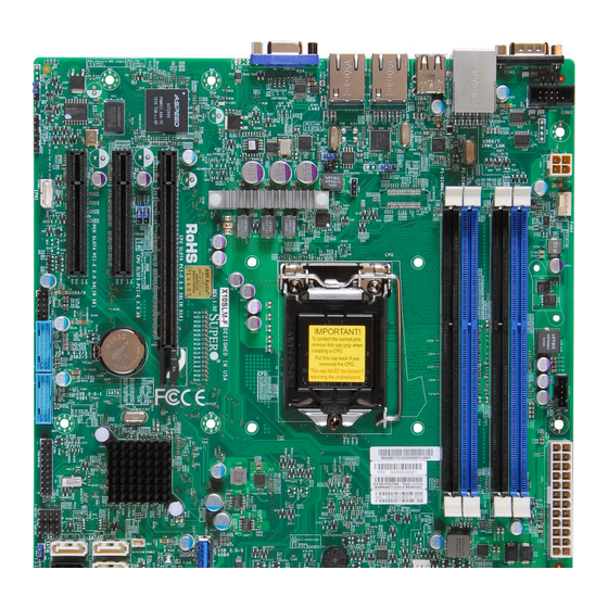
About This Motherboard
Describes the motherboard, its processors, and chipset.
Manual Organization
Outlines the structure and content of each chapter.
Conventions Used in the Manual
Explains symbols and their meanings in the manual.
Contacting Supermicro
Provides contact details for Supermicro headquarters and regional offices.
Chapter 1 Introduction
1-1 Overview
Introduces the motherboard and lists included components in the retail box.
1-2 Chipset Overview
Details the Intel C224/C222 Express chipset features and capabilities.
1-3 Special Features
Covers features like AC Power Loss recovery and system resource alerts.
1-4 PC Health Monitoring
Explains system health monitoring, fan control, and temperature monitoring.
1-5 ACPI Features
Describes Advanced Configuration and Power Interface for power management.
1-6 Power Supply
Discusses power supply requirements, connectors, and recommendations.
Chapter 2 Installation
2-1 Standardized Warning Statements
Provides industry-standard warnings for installation and handling.
2-2 Static-Sensitive Devices
Explains ESD precautions and proper handling procedures.
2-3 Processor and Heatsink Installation
Guides on installing the CPU and its heatsink correctly.
2-4 Installing DDR3 Memory
Details the process of installing DDR3 memory modules.
2-5 Motherboard Installation
Provides instructions on mounting the motherboard into the chassis.
2-6 Connectors/IO Ports
Describes various onboard connectors and back panel I/O ports.
2-7 Connecting Cables
Explains pin-out definitions for onboard headers and connectors.
2-8 Jumper Settings
Details the function and configuration of motherboard jumpers.
2-9 Onboard Indicators
Explains the status and meaning of onboard LEDs.
2-10 Serial ATA (SATA) Connections
Describes SATA port configurations and pin definitions.
Chapter 3 Troubleshooting
3-1 Troubleshooting Procedures
Offers step-by-step guidance for common system issues.
3-2 Technical Support Procedures
Outlines steps before contacting technical support.
3-3 Frequently Asked Questions
Addresses common user queries and their solutions.
3-4 Battery Removal and Installation
Details how to remove and install the CMOS battery.
3-5 Returning Merchandise for Service
Explains the process for warranty service and RMA.
Chapter 4 BIOS
4-1 Introduction
Introduces the AMI BIOS Setup Utility and its navigation.
4-2 Main Setup
Describes the main BIOS setup screen and its elements.
4-3 Advanced Setup Configurations
Covers various advanced BIOS settings.
4-4 Event Logs
Explains how to configure and view system event logs.
4-5 Boot Settings
Details options for configuring system boot order and devices.
4-6 Security Settings
Covers BIOS password and security configurations.
4-7 Save & Exit
Explains how to save changes and exit the BIOS setup.
Appendix A BIOS Error Beep Codes
A-1 BIOS Error Beep Codes
Lists beep codes and their corresponding error messages.
Appendix B Software Installation Instructions
B-1 Installing Software Programs
Guides on installing drivers and utilities from Supermicro.
B-2 Installing SuperDoctor5
Explains how to install the SuperDoctor5 hardware monitoring tool.
Appendix C UEFI BIOS Recovery Instructions
C-1 An Overview to the UEFI BIOS
Provides a general introduction to UEFI BIOS.
C-2 How to Recover the UEFI BIOS Image (-the Main BIOS Block)
Explains the UEFI BIOS recovery process.
C-3 To Recover the Main BIOS Block Using a USB-Attached Device
Details recovery using a USB device.
Appendix D Dual Boot Block
D-1 Introduction
Introduces the Dual Boot Block feature for BIOS recovery.
D-2 Steps to Reboot the System by Using Jumper JBR1
Provides instructions for rebooting using JBR1 jumper.
Table of Contents
Save PDF
Print
Rename the bookmark
Delete bookmark?
Delete from my manuals?
Login
Sign In
OR
Sign in with Facebook
Sign in with Google
Upload manual
Upload from disk
Upload from URL
Need help?
Do you have a question about the X10SLL-F and is the answer not in the manual?
Questions and answers