Table of Contents
Advertisement
Advertisement
Table of Contents

Related Manuals for Super X10DRi


Summary of Contents for Super X10DRi
- Page 1 X10DRi X10DRi-T USER’S MANUAL Revision 1.0...
- Page 2 Manual Revision 1.0 Release Date: Sept. 23, 2014 Unless you request and receive written permission from Super Micro Computer, Inc., you may not copy any part of this document. Information in this document is subject to change without notice. Other products and companies referred to herein are trademarks or registered trademarks of their respective companies or mark holders.
-
Page 3: About This Motherboard
PC users. It provides information for the installation and use of the X10DRi/X10DRi-T motherboard. About This Motherboard The Super X10DRi/X10DRi-T motherboard supports dual Intel E5-2600v3 Series Processors (Socket R3) that offer new Intel Microarchitecture 22nm Process Technology, delivering system performance, power efficiency, and feature sets to address the needs of next-generation computer users. -
Page 4: Conventions Used In The Manual
X10DRi/X10DRi-T Motherboard User’s Manual Conventions Used in the Manual Pay special attention to the following symbols for proper system installation: Warning: Important information given to ensure proper system installation or to prevent damage to the components or injury to yourself;... -
Page 5: Contacting Supermicro
Preface Contacting Supermicro Headquarters Address: Super Micro Computer, Inc. 980 Rock Ave. San Jose, CA 95131 U.S.A. Tel: +1 (408) 503-8000 Fax: +1 (408) 503-8008 Email: marketing@supermicro.com (General Information) support@supermicro.com (Technical Support) Website: www.supermicro.com Europe Address: Super Micro Computer B.V. -
Page 6: Table Of Contents
X10DRi/X10DRi-T Motherboard User’s Manual Table of Contents Preface Chapter 1 Overview Overview ......................1-1 Processor and Chipset Overview..............1-11 Special Features ................... 1-12 System Health Monitoring ................1-12 ACPI Features ....................1-13 Power Supply ....................1-13 Advanced Power Management ..............1-14... - Page 7 Table of Contents NIC1/NIC2 LED Indicators ............... 2-23 Overheat (OH)/Fan Fail/PWR Fail/UID LED ..........2-24 Power Fail LED ..................2-24 Reset Button ................... 2-25 Power Button ................... 2-25 Connecting Cables ..................2-26 Power Connectors ................... 2-26 Fan Headers ..................... 2-27 Chassis Intrusion ..................
- Page 8 X10DRi/X10DRi-T Motherboard User’s Manual Proper Battery Disposal .................. 3-6 Frequently Asked Questions ................3-7 Returning Merchandise for Service..............3-8 Chapter 4 BIOS Introduction ...................... 4-1 Main Setup ...................... 4-2 Advanced Setup Configurations..............4-4 Event Logs ....................4-29 IPMI ....................... 4-31 Security Settings ...................
-
Page 9: Chapter 1 Overview
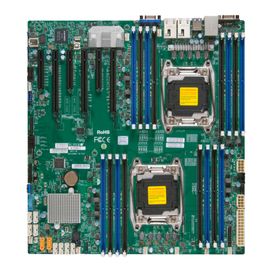
Chapter 1: Overview Chapter 1 Overview Overview Checklist Congratulations on purchasing your computer motherboard from an acknowledged leader in the industry. Supermicro boards are designed with the utmost attention to detail to provide you with the highest standards in quality and performance. Please check that the following items have all been included with your motherboard. - Page 10 X10DRi/X10DRi-T Motherboard User’s Manual Motherboard Image Note: All graphics shown in this manual were based upon the latest PCB Revision available at the time of publishing of the manual. The motherboard you've received may or may not look exactly the same as the graphics...
-
Page 11: Motherboard Layout
USB0/1 (2.0) COM1 JUIDB1 LAN CTRL Fan5 LEDM1 IPMI_LAN LAN1 LAN2 BIOS CLOSE 1st CPU2 OPEN 1st X10DRi-(T) Rev. 1.02 T-SGPIO1 T-SGPIO2 T-SGPIO3 Battery CLOSE 1st CPU1 Intel PCH OPEN 1st JSD2 JOH1 JSD1 I-SATA0 Note: For the latest CPU/Memory updates, please refer to our website at... - Page 12 • Jumpers/LED Indicators not indicated are for testing only. • LAN1/LAN2 ports support Gigabit LAN (GLAN) connections on the X10DRi, and 10G (T) LAN connections on the X10DRi-T. • Use only the correct type of onboard CMOS battery as specified by the manufac-...
- Page 13 JTPM1 TPM (Trusted Platform Module)/Port 80 Header JUIDB1 UID (Unit Identification) Button LAN1/LAN2 G-bit Ethernet (GLAN) Ports 1/2 (X10DRi) 10G-bit Ethernet (TLAN) Ports 1/2 (X10DRi-T) (IPMI) LAN IPMI_Dedicated LAN support by the Aspeed controller (I-)SATA 0-5 SATA 3.0 Connectors supported by Intel PCH (I-SATA 0-5),...
- Page 14 X10DRi/X10DRi-T Motherboard User’s Manual (CPU2) Slot4 PCI-Express 3.0 x16 Slot from CPU2 (CPU2)Slot5 PCI-Express 3.0 x8 Slot from CPU2 (CPU1)Slot6 PCI-Express 3.0 x16 Slot from CPU2 (T-)SGPIO1/2/3 Seria_Link General Purpose I/O Headers 1/2/3 (for SATA ports), (T-SGPIO1 for I-SATA0-3, T-SGPIO2 for I-SATA4/5, T-...
-
Page 15: Motherboard Features
Graphics Graphics Controller via Aspeed 2400 BMC • Network Intel i350 Gigabit (10/100/1000 Mb/s) Ethernet Con- troller for LAN 1/LAN 2 ports (X10DRi), • Intel X540 10_Gigabit (T) Ethernet Controller for LAN 1/LAN 2 ports (X10DRi-T), • Aspeed 2400 Base-board Controller (BMC) supports IPMI 2.0... -
Page 16: Peripheral Devices
X10DRi/X10DRi-T Motherboard User’s Manual Serial (COM) Port • One (1) Fast UART 16550 Port • One (1) Header Peripheral USB Devices Devices • Two (2) USB 2.0 ports on the rear I/O panel (USB 0/1), • Two (2) USB 3.0 ports on the rear I/O panel (USB 6/7), •... - Page 17 Chapter 1: Overview • Dual Cooling Zone • Low noise fan speed control • Pulse Width Modulation (PWM) fan control • System PECI (Platform Environment Configuration Interface) Management 2.0 support • UID (Unit Identification)/Remote UID • System resource alert via SuperDoctor 5 •...
-
Page 18: System Block Diagram
X10DRi/X10DRi-T Motherboard User’s Manual #1-8 #2-8 #1-7 #2-7 #1-6 #2-6 #1-5 #2-5 #1-4 #2-4 #1-3 #2-3 #1-2 #2-2 Processor #1-1 Processor #2-1 9.6G DDR-IV DDR-IV 9.6G SLOT 2 #1 #3B #2 #3 PCI-E X16 G3 (LANE REVERSE) SLOT 3 PCI-E X8 G3 (LANE REVERSE) -
Page 19: Processor And Chipset Overview
Processor and Chipset Overview Built upon the functionality and capability of the Intel E5-2600v3 Series processors (Socket R3) and the Intel C612 PCH, the X10DRi/X10DRi-T motherboard provides system performance, power efficiency, and feature sets to address the needs of next-generation computer users. -
Page 20: Special Features
X10DRi/X10DRi-T Motherboard User’s Manual Special Features Recovery from AC Power Loss The Basic I/O System (BIOS) provides a setting that determines how the system will respond when AC power is lost and then restored to the system. You can choose for the system to remain powered off (in which case you must press the power switch to turn it back on), or for it to automatically return to the power-on state. -
Page 21: Acpi Features
It is even more important for processors that have high CPU clock rates. The X10DRi/X10DRi-T motherboard accommodates 24-pin ATX power supplies. Although most power supplies generally meet the specifications required by the CPU, some are inadequate. In addition, two 12V 8-pin power connections are also required to ensure adequate power supply to the system. -
Page 22: Advanced Power Management
X10DRi/X10DRi-T Motherboard User’s Manual Advanced Power Management The following new advanced power management features are supported by this motherboard: Intel Intelligent Power Node Manager (NM) (Available ® when the Supermicro Power Manager [SPM] is Installed) The Intel Intelligent Power Node Manager 3.0 (IPNM) provides your system with ®... -
Page 23: Chapter 2 Installation
Chapter 2: Installation Chapter 2 Installation Standardized Warning Statements The following statements are industry-standard warnings, provided to warn the user of situations which have the potential for bodily injury. Should you have questions or experience difficulty, contact Supermicro's Technical Support department for assis- tance. - Page 24 X10DRi/X10DRi-T Motherboard User’s Manual Attention Danger d'explosion si la pile n'est pas remplacée correctement. Ne la remplacer que par une pile de type semblable ou équivalent, recommandée par le fabricant. Jeter les piles usagées conformément aux instructions du fabricant. ¡Advertencia! Existe peligro de explosión si la batería se reemplaza de manera incorrecta.
-
Page 25: Product Disposal
Chapter 2: Installation Product Disposal Warning! Ultimate disposal of this product should be handled according to all national laws and regulations. 製品の廃棄 この製品を廃棄処分する場合、 国の関係する全ての法律 ・ 条例に従い処理する必要が あります。 警告 本产品的废弃处理应根据所有国家的法律和规章进行。 警告 本產品的廢棄處理應根據所有國家的法律和規章進行。 Warnung Die Entsorgung dieses Produkts sollte gemäß allen Bestimmungen und Gesetzen des Landes erfolgen. -
Page 26: Static-Sensitive Devices
X10DRi/X10DRi-T Motherboard User’s Manual القىانين واللىائح الىطنية جميع وفقا ل ينبغي التعامل معه هذا المنتج من التخلص النهائي عند 경고! 이 제품은 해당 국가의 관련 법규 및 규정에 따라 폐기되어야 합니다. Waarschuwing De uiteindelijke verwijdering van dit product dient te geschieden in overeenstemming met alle nationale wetten en reglementen. -
Page 27: Motherboard Installation
USB0/1 (2.0) COM1 JUIDB1 LAN CTRL Fan5 LEDM1 IPMI_LAN LAN1 LAN2 BIOS CLOSE 1st CPU2 OPEN 1st X10DRi-(T) Rev. 1.02 T-SGPIO1 T-SGPIO2 T-SGPIO3 Battery CLOSE 1st CPU1 Intel PCH OPEN 1st JSD2 JOH1 JSD1 I-SATA0 Caution: 1) To avoid damaging the motherboard and its components, please do not use a force greater than 8 lb/inch on each mounting screw during motherboard installation. -
Page 28: Installing The Motherboard
X10DRi/X10DRi-T Motherboard User’s Manual Installing the Motherboard Note: Always connect the power cord last, and always remove it before adding, removing or changing any hardware components. 1. Install the I/O shield into the chassis. 2. Locate the mounting holes on the motherboard. -
Page 29: Processor And Heatsink Installation
Chapter 2: Installation Processor and Heatsink Installation Warning: When handling the processor package, avoid placing direct pressure on the label area. Also, improper CPU installation or socket/pin misalignment can cause serious damage to the CPU or the motherboard that will require RMA repairs. Be sure to read and follow all instructions thoroughly before installing your CPU and heatsink. - Page 30 X10DRi/X10DRi-T Motherboard User’s Manual 2. Press the second load lever labeled 'Close 1st' to release the load plate that covers the CPU socket from its locking position. Pull lever away from Press down on Load the socket Lever 'Close 1st' 3.
- Page 31 Chapter 2: Installation 4. Use your thumb and the index finger to loosen the lever and open the load plate. 5. Using your thumb and index finger, hold the CPU on its edges. Align the CPU keys, which are semi-circle cutouts, against the socket keys. Socket Keys CPU Keys 6.
- Page 32 X10DRi/X10DRi-T Motherboard User’s Manual 7. With the CPU inside the socket, inspect the four corners of the CPU to make sure that the CPU is properly installed. Gently close Push down and lock the the load plate. lever labelled 'Close 1st'.
-
Page 33: Installing A Passive Cpu Heatsink
Chapter 2: Installation Installing a Passive CPU Heatsink 1. Do not apply any thermal grease to the heatsink or the CPU die -- the re- quired amount has already been applied. 2. Place the heatsink on top of the CPU so that the four mounting holes are aligned with those on the Motherboard and the Heatsink Bracket underneath. -
Page 34: Removing The Heatsink
X10DRi/X10DRi-T Motherboard User’s Manual Removing the Heatsink Warning: We do not recommend that the CPU or the heatsink be removed. However, if you do need to uninstall the heatsink, please follow the instructions below to uninstall the heatsink to prevent damage done to the CPU or the CPU socket. -
Page 35: Installing And Removing The Memory Modules
USB0/1 (2.0) JUIDB1 COM1 LAN CTRL Fan5 LEDM1 IPMI_LAN LAN1 LAN2 BIOS Notches CLOSE 1st CPU2 OPEN 1st X10DRi-(T) Rev. 1.02 T-SGPIO1 T-SGPIO2 T-SGPIO3 Release Tabs Battery CLOSE 1st CPU1 Intel PCH OPEN 1st JSD2 JOH1 JSD1 I-SATA0 3. Align the key of the DIMM module with the receptive point on the memory slot. - Page 36 X10DRi/X10DRi-T Motherboard User’s Manual Memory Support for the X10DRi/X10DRi-T Motherboard The X10DRi/X10DRi-T Motherboard supports up to 1024 GB of Load Reduced (LRDIMM) or 512 GB of Registered (RDIMM) DDR4 (288-pin) ECC 2133/1866/1600 MHz modules in 16 slots. Memory speed support depends upon the CPUs installed in the motherboard.
- Page 37 Chapter 2: Installation Populating RDIMM/LRDIMM ECC Memory Modules Speed (MT/s) Voltage (V) ...
-
Page 38: Control Panel Connectors And I/O Ports
3. Back Panel USB 2.0 Port 1 4. IPMI_Dedicated LAN 5. Back Panel USB 3.0 Port 6 6. Back Panel USB 3.0 Port 7 7. Gigabit LAN 1 (X10DRi), (10G) TLAN 1 (X10DRi-T) 8. Gigabit LAN 2 (X10DRi), (10G) TLAN 2 (X10DRi-T) 9. -
Page 39: Serial Ports
USB0/1 (2.0) JUIDB1 COM1 2. COM2 LAN CTRL Fan5 LEDM1 IPMI_LAN LAN2 LAN1 BIOS 3. VGA CLOSE 1st CPU2 OPEN 1st X10DRi-(T) Rev. 1.02 T-SGPIO1 T-SGPIO2 T-SGPIO3 Battery CLOSE 1st CPU1 Intel PCH OPEN 1st JSD2 JOH1 JSD1 I-SATA0 2-17... -
Page 40: Universal Serial Bus (Usb)
X10DRi/X10DRi-T Motherboard User’s Manual Universal Serial Bus (USB) Back Panel USB (2.0) 0/1 Pin Definitions Two USB 2.0 ports (USB 0/1) and two Pin# Definition Pin# Definition USB 3.0 ports (USB6/7) are located on the I/O backpanel. In addition, USB_PN1 USB_PN0 two internal USB 2.0 headers (J25/... -
Page 41: Ethernet Ports
1_GbE LANs TD0- P3V3SB on the X10 DRi, and 10_GbE LANs TD1+ Link 100 LED on the X10DRi-T. In addition, an (Yellow, +3V3SB) IPMI_Dedicated LAN is located above TD1- Link 1000 LED USB 0/1 ports on the backplane. All (Yellow, +3V3SB) these ports accept RJ45 type cables. -
Page 42: Unit Identifier Switch/Uid Led Indicator
X10DRi/X10DRi-T Motherboard User’s Manual Unit Identifier Switches/UID LED UID Switch Indicators Pin# Definition A rear Unit Identifier (UID) switch and a Ground rear UID LED (LE1) are located next to the Ground VGA port on the motherboard. The front Button In... -
Page 43: Front Control Panel
JF1 Header Pins USB6/7(3.0) USB0/1 (2.0) COM1 JUIDB1 LAN CTRL Fan5 LEDM1 IPMI_LAN LAN1 LAN2 BIOS CLOSE 1st CPU2 OPEN 1st X10DRi-(T) Rev. 1.02 T-SGPIO1 T-SGPIO2 T-SGPIO3 Battery CLOSE 1st CPU1 Intel PCH OPEN 1st JSD2 JOH1 JSD1 I-SATA0 Ground 3.3 V... -
Page 44: Front Control Panel Pin Definitions
X10DRi/X10DRi-T Motherboard User’s Manual Front Control Panel Pin Definitions NMI Button NMI Button Pin Definitions (JF1) The non-maskable interrupt button Pin# Definition header is located on pins 19 and 20 Control of JF1. Refer to the table on the right Ground for pin definitions. -
Page 45: Hdd/Uid Led
C. NIC2 LED IPMI_LAN LAN1 LAN2 BIOS Ground CLOSE 1st CPU2 3.3 V OPEN 1st FP PWRLED X10DRi-(T) UID Switch HDD LED Rev. 1.02 T-SGPIO1 NIC1 Link LED NIC1 Activity LED T-SGPIO2 T-SGPIO3 NIC2 Activity LED NIC2 Link LED Battery... -
Page 46: Overheat (Oh)/Fan Fail/Pwr Fail/Uid Led
X10DRi/X10DRi-T Motherboard User’s Manual Overheat (OH)/Fan Fail/PWR Fail/ OH/Fan Fail/ PWR Fail/Blue_UID UID LED LED Pin Definitions (JF1) Pin# Definition Connect an LED cable to pins 7 Blue_UID LED and 8 of Front Control Panel to use the Overheat/Fan Fail/Power Fail OH/Fan Fail/Power Fail and UID LED connections. -
Page 47: Reset Button
Fan5 LEDM1 IPMI_LAN LAN1 LAN2 BIOS Ground CLOSE 1st CPU2 3.3 V FP PWRLED OPEN 1st X10DRi-(T) UID Switch HDD LED Rev. 1.02 T-SGPIO1 NIC1 Link LED NIC1 Activity LED T-SGPIO2 T-SGPIO3 NIC2 Activity LED NIC2 Link LED Battery OH/Fan Fail/... -
Page 48: Connecting Cables
X10DRi/X10DRi-T Motherboard User’s Manual Connecting Cables Power Connectors ATX Power 24-pin Connector Pin Definitions (JPW1) A 24-pin main power supply connector Pin# Definition Pin # Definition (J24), and two 8-pin CPU power connec- +3.3V +3.3V tors (JPWR1/ JPWR2) are located on the -12V (NC) +3.3V... -
Page 49: Fan Headers
C. Fan 3 BIOS D. Fan 4 CLOSE 1st E. Fan 5 CPU2 F. Fan 6 G. Fan A OPEN 1st H. Fan B I. Chassis Intrusion X10DRi-(T) Rev. 1.02 T-SGPIO1 T-SGPIO2 T-SGPIO3 Battery CLOSE 1st CPU1 Intel PCH OPEN 1st JSD2... -
Page 50: Internal Speaker
JSD1/JSD2 on Ground the motherboard. These connectors, colored Ground in yellow, are used with Supermicro Super- DOMs, which have power-pins built in and do not require separate external power cables. These connectors are also back-compatible with non-Supermicro SATADOMs that require external power. -
Page 51: Tpm/Port 80 Header
COM1 JUIDB1 A. TPM/Port 80 Header LAN CTRL B. JOH1 Fan5 LEDM1 IPMI_LAN LAN1 LAN2 BIOS CLOSE 1st CPU2 OPEN 1st X10DRi-(T) Rev. 1.02 T-SGPIO1 T-SGPIO2 T-SGPIO3 Battery CLOSE 1st CPU1 Intel PCH OPEN 1st JSD2 JOH1 JSD1 I-SATA0 2-29... -
Page 52: Connector
X10DRi/X10DRi-T Motherboard User’s Manual Power SMB (I C) Connector PWR SMB Pin Definitions Power System Management Bus (I Pin# Definition Connector (JPI C1) monitors power Clock supply, fan and system temperatures. Data See the table on the right for pin PMBUS_Alert definitions. -
Page 53: T-Sgpio 1/2/3 Headers
JUIDB1 B. T-SGPIO2 LAN CTRL Fan5 LEDM1 IPMI_LAN LAN1 LAN2 BIOS C. T-SGPIO3 D. Standby PWR CLOSE 1st CPU2 OPEN 1st X10DRi-(T) Rev. 1.02 T-SGPIO1 T-SGPIO2 T-SGPIO3 Battery CLOSE 1st CPU1 Intel PCH OPEN 1st JSD2 JOH1 JSD1 I-SATA0 2-31... -
Page 54: Power Led/Speaker
X10DRi/X10DRi-T Motherboard User’s Manual Power LED/Speaker PWR LED Connector Pin Definitions Pins 1-3 of JD1 are used for power Pin Setting Definition LED indication, and pins 4-7 are for Pin 1 JD1_PIN1 the speaker. See the tables on the Pin 2 FP_PWR_LED right for pin definitions. -
Page 55: Jumper Settings
LAN Enable/Disable LAN Enable Jumper Settings JPL1 enables or disables Gigabit LAN Jumper Setting Definition ports 1/2 on the X10DRi and 10G-LAN Enabled (default) (TLAN) ports 1/2 on the X10DRi-T. See Disabled the table on the right for jumper- settings. -
Page 56: Cmos Clear
X10DRi/X10DRi-T Motherboard User’s Manual CMOS Clear JBT1 is used to clear CMOS. Instead of pins, this "jumper" consists of contact pads to prevent accidental clearing of CMOS. To clear CMOS, use a metal object such as a small screwdriver to touch both pads at the same time to short the connection. -
Page 57: Vga Enable
VGA Enabled USB6/7(3.0) USB0/1 (2.0) COM1 JUIDB1 BMC Enabled LAN CTRL Fan5 LEDM1 IPMI_LAN LAN1 LAN2 BIOS CLOSE 1st CPU2 OPEN 1st X10DRi-(T) Rev. 1.02 T-SGPIO1 T-SGPIO2 T-SGPIO3 Battery CLOSE 1st CPU1 Intel PCH OPEN 1st JSD2 JOH1 JSD1 I-SATA0 2-35... -
Page 58: I 2 C Bus To Pci-Exp. Slots
X10DRi/X10DRi-T Motherboard User’s Manual C Bus to PCI-Exp. Slots C for PCI-E slots Jumper Settings Use Jumpers JI C1 and JI C2 to connect Jumper Setting Definition the System Management Bus (I C) to Pins 1-2 Enabled PCI-Express slots to improve PCI per-... -
Page 59: Onboard Led Indicators
LEDs. The green LED Green Flashing Active indicates activity, while the other 10G-LAN 1/2 Link LED (Left) GLAN 1/2 Link LED (Left) LED State (For X10DRI-T) LED State (For X10DRi) Link LED may be green, amber or LED Color Definition LED Color Definition... -
Page 60: Onboard Power Led
X10DRi/X10DRi-T Motherboard User’s Manual Onboard Power LED Onboard PWR LED Indicator LED States An Onboard Power LED is located at LE2 LED Color Definition on the motherboard. When this LED is on, System Off (PWR cable not connected) the system is on. Be sure to turn off the... -
Page 61: 2-10 Sata Connections
LAN1 LAN2 BIOS D. I-SATA3 E. I-SATA4 CLOSE 1st F. I-SATA5 CPU2 G. S-SATA0 H. S-SATA1 I. S-SATA2 OPEN 1st J. S-SATA3 X10DRi-(T) Rev. 1.02 T-SGPIO1 T-SGPIO2 T-SGPIO3 Battery CLOSE 1st CPU1 Intel PCH OPEN 1st JSD2 JOH1 JSD1 I-SATA0... - Page 62 X10DRi/X10DRi-T Motherboard User’s Manual Notes 2-40...
-
Page 63: Chapter 3 Troubleshooting
Chapter 3: Troubleshooting Chapter 3 Troubleshooting Troubleshooting Procedures Use the following procedures to troubleshoot your system. If you have followed all of the procedures below and still need assistance, refer to the ‘Technical Support Procedures’ and/or ‘Returning Merchandise for Service’ section(s) in this chapter. Note: Always disconnect the power cord before adding, changing or installing any hardware components. -
Page 64: System Boot Failure
X10DRi/X10DRi-T Motherboard User’s Manual No Video 1. If the power is on, but you have no video, remove all the add-on cards and cables. 2. Use the speaker to determine if any beep codes exist. Refer to Appendix A for details on beep codes. -
Page 65: Memory Errors
Chapter 3: Troubleshooting Memory Errors When a No-Memory Beep Code is issued by the system, check the following: 1. Make sure that the memory modules are compatible with the system and that the DIMM modules are properly and fully installed. (For memory compatibility, refer to the Memory Compatibility Chart posted on our website @ http://www. -
Page 66: Technical Support Procedures
X10DRi/X10DRi-T Motherboard User’s Manual tings in the BIOS to make sure that the CPU and System temperatures are within the normal range. Also check the front panel Overheat LED, and make sure that the Overheat LED is not on. 5. Adequate power supply: Make sure that the power supply provides adequate power to the system. - Page 67 Chapter 3: Troubleshooting through its channels, so it is best to first check with your distributor or reseller for troubleshooting services. They should know of any possible problem(s) with the specific system configuration that was sold to you. 1. Please go through the ‘Troubleshooting Procedures’ and 'Frequently Asked Question' (FAQ) sections in this chapter or see the FAQs on our website (http://www.supermicro.com/) before contacting Technical Support.
-
Page 68: Battery Removal And Installation
X10DRi/X10DRi-T Motherboard User’s Manual Battery Removal and Installation Battery Removal To remove the onboard battery, follow the steps below: 1. Power off your system and unplug your power cable. 2. Locate the onboard battery as shown below. 3. Using a tool such as a pen or a small screwdriver, push the battery lock out- wards to unlock it. -
Page 69: Frequently Asked Questions
Chapter 3: Troubleshooting Frequently Asked Questions Question: What are the various types of memory that my motherboard can support? Answer: The motherboard supports Registered ECC DDR4 DIMM modules. To enhance memory performance, do not mix memory modules of different speeds and sizes. -
Page 70: Returning Merchandise For Service
X10DRi/X10DRi-T Motherboard User’s Manual Returning Merchandise for Service A receipt or copy of your invoice marked with the date of purchase is required before any warranty service will be rendered. You can obtain service by calling your ven- dor for a Returned Merchandise Authorization (RMA) number. When returning the... -
Page 71: Chapter 4 Bios
BIOS Introduction This chapter describes the AMI BIOS setup utility for the X10DRi/X10DRi-T. The ROM BIOS is stored in a Flash EEPROM and can be easily updated. This chapter describes the basic navigation of the AMI BIOS setup utility screens. -
Page 72: How To Start The Setup Utility
X10DRi/X10DRi-T User’s Manual How to Start the Setup Utility Normally, the only visible Power-On Self-Test (POST) routine is the memory test. As the memory is being tested, press the <Delete> key to enter the main menu of the AMI BIOS setup utility. From the main menu, you can access the other setup screens. - Page 73 Note: The time is in the 24-hour format. For example, 5:30 P.M. appears as 17:30:00. Supermicro X10DRi Version: This item displays the version of the BIOS ROM used in the system. Build Date: This item displays the date when the version of the BIOS ROM used in the system was built.
-
Page 74: Advanced Setup Configurations
X10DRi/X10DRi-T User’s Manual Advanced Setup Configurations Use the arrow keys to select Advanced setup and press <Enter> to access the submenu items: Warning: Take Caution when changing the Advanced settings. An incorrect value, a very high DRAM frequency or an incorrect BIOS timing setting may cause the system to malfunction. -
Page 75: Power Configuration
Chapter 4: AMI BIOS Wait For 'F1' If Error Select Enabled to force the system to wait until the 'F1' key is pressed if an error occurs. The options are Disabled and Enabled. Interrupt 19 Capture Interrupt 19 is the software interrupt that handles the boot disk function. When this item is set to Immediate, the ROM BIOS of the host adaptors will "capture"... -
Page 76: Cpu Configuration
X10DRi/X10DRi-T User’s Manual CPU Configuration North Bridge This feature allows the user to configure the settings for the Intel North Bridge. IIO Configuration EV DFX (Device Function On-Hide) Features When this feature is set to Enable, the EV_DFX Lock Bits that are located on a processor will always remain clear during electric tuning. - Page 77 Chapter 4: AMI BIOS The following items will be display: PCI-E Port Link Status PCI-E Port Link Max PCI-E Port Link Speed PCI-E Port L0s Exit Latency Use this feature to set the length of time required for the port specified by the user to complete the transition from L0s to L0.
- Page 78 X10DRi/X10DRi-T User’s Manual No PCIe Port Active ECO Use this feature to select a workaround setting to implement the engineering- change order (ECO) on the system when PCI ports are not active. The options are PCU Squelch exit ignore option and Reset the SQ FLOP by CSR option.
- Page 79 Chapter 4: AMI BIOS Coherency Support (Isoch) Select Enable for the Iscoh VT-d engine to pass through ATS to enhance system performance. The options are Enable and Disable. QPI (Quick Path Interconnect) Configuration The following QPI information will be displayed: •...
-
Page 80: Memory Configuration
X10DRi/X10DRi-T User’s Manual Memory Configuration Enforce POR Select Enable to enforce POR restrictions on DDR4 frequency and voltage pro- gramming. The options are Auto, Enforce POR, Disabled and Enforce Stretch Goals. Memory Frequency Use this feature to set the maximum memory frequency for onboard memory modules. -
Page 81: Dimm Information
Chapter 4: AMI BIOS Rank Interleaving Use this item to select a rank memory interleaving method. The options are Auto, 1-Way, 2-Way, 4-Way, and 8-Way. A7 Mode Select Enabled to support the A7 (Addressing) mode to improve memory per- formance. The options are Enable and Disable. DIMM Information This item displays the status of a DIMM module specified by the user. -
Page 82: South Bridge Configuration
X10DRi/X10DRi-T User’s Manual write back one cache line every 16K cycles, if there is no delay caused by internal processing. By using this method, roughly 64 GB of memory behind the IO hub will be scrubbed every day. The options are Enable and Disable. - Page 83 Chapter 4: AMI BIOS XHCI Hand-Off This is a work-around solution for operating systems that do not support XHCI (Ex- tensible Host Controller Interface) hand-off. The XHCI ownership change should be claimed by the XHCI driver. The settings are Enabled and Disabled. EHCI Hand-Off This item is for operating systems that do not support Enhanced Host Controller Interface (EHCI) hand-off.
-
Page 84: Sata Configuration
X10DRi/X10DRi-T User’s Manual SATA Configuration When this submenu is selected, AMI BIOS automatically detects the presence of the SATA devices that are supported by the Intel PCH chip and displays the fol- lowing items: SATA Controller This item enables or disables the onboard SATA controller supported by the Intel PCH chip. - Page 85 Chapter 4: AMI BIOS Port 0 ~ Port 5 SATA Device Type Use this item to specify if the SATA port specified by the user should be con- nected to a Solid State drive or a Hard Disk Drive. The options are Hard Disk Drive and Solid State Drive.
-
Page 86: Ssata Configuration
X10DRi/X10DRi-T User’s Manual Port 0 ~ Port 5 Hot Plug Select Enabled to enable hot-plugging support for a port specified by the user, which will allow the user to replace a SATA disk drive installed on this port without shutting down the system. The options are Enabled and Disabled. - Page 87 Chapter 4: AMI BIOS • Software Preserve Support sSATA Port 0~ Port 3 Select Enabled to enable an sSATA port specified by the user. The options are Disabled and Enabled. sSATA Port 0 ~ Port 3 Hot Plug Select Enabled to enable hot-plugging support for a port specified by the user, which will allow the user to replace a sSATA disk drive installed on this port without shutting down the system.
- Page 88 X10DRi/X10DRi-T User’s Manual sSATA RAID Option ROM/UEFI Driver Select EFI to load the EFI driver for system boot. Select Legacy to load a legacy driver for system boot. The options are Disabled, EFI, and Legacy. sSATA Port 0~ Port 3 This item displays the information detected on the installed sSATA drives on the particular sSATA port.
- Page 89 Chapter 4: AMI BIOS • ME Firmware Status #2 • Current State • Error Code Altitude This feature indicates the altitude of the platform this machine is located above the sea level. The value is shown in meters. If the value is unknown, enter the number "80000000".
- Page 90 X10DRi/X10DRi-T User’s Manual Above 4G Decoding (Available if the system supports 64-bit PCI decoding) Select Enabled to decode a PCI device that supports 64-bit in the space above 4G Address. The options are Enabled and Disabled. SR-IOV (Available if the system supports Single-Root Virtualization) Select Enabled for Single-Root IO Virtualization support.
-
Page 91: Super Io Configuration
Extensible Firmware Interface) for network stack support. The options are Enabled and Disabled. Super IO Configuration Super IO Chip AST2400 Serial Port 1 Configuration/Serial Port 2 Configuration Serial Port 1/Serial Port 2 Select Enabled to enable the onboard serial port specified by the user. The options are Enabled and Disabled. -
Page 92: Serial Port Console Redirection
X10DRi/X10DRi-T User’s Manual Device Mode Use this feature to configure SUART clock source settings. The options are 24MHz/13 and 24MHz. Serial Port 2 Attribute Select SOL to use COM Port 2 as a Serial_Over_LAN (SOL) port for console redi- rection. The options are COM and SOL. - Page 93 Chapter 4: AMI BIOS is odd. Select None if you do not want to send a parity bit with your data bits in transmission. Select Mark to add a mark as a parity bit to be sent along with the data bits. Select Space to add a Space as a parity bit to be sent with your data bits.
- Page 94 X10DRi/X10DRi-T User’s Manual SOL/COM2 Console Redirection Select Enabled to use the SOL port for Console Redirection. The options are Enabled and Disabled. *If the item above set to Enabled, the following items will become available for user's configuration: SOL/COM2 Console Redirection Settings Use this feature to specify how the host computer will exchange data with the client computer, which is the remote computer used by the user.
- Page 95 Chapter 4: AMI BIOS Flow Control Use this feature to set the flow control for Console Redirection to prevent data loss caused by buffer overflow. Send a "Stop" signal to stop sending data when the receiving buffer is full. Send a "Start" signal to start data-sending when the receiving buffer is empty.
- Page 96 X10DRi/X10DRi-T User’s Manual *If the item above set to Enabled, the following items will become available for user's configuration: Out-of-Band Management Port The feature selects a serial port in a client server to be used by the Windows Emergency Management Services (EMS) to communicate with a remote host server.
- Page 97 Chapter 4: AMI BIOS Trusted Computing (Available when a TPM device is installed and detected by the BIOS) Configuration Security Device Support If this feature and the TPM jumper on the motherboard are both set to Enabled, onboard security devices will be enabled for TPM support to enhance data integrity and network security.
-
Page 98: Acpi Settings
X10DRi/X10DRi-T User’s Manual ACPI Settings WHEA Support Select Enabled to support the Windows Hardware Error Architecture (WHEA) plat- form and provide a common infrastructure for the system to handle hardware errors within the Windows OS environment to reduce system crashes and to enhance system recovery and health monitoring. -
Page 99: Event Logs
Chapter 4: AMI BIOS Event Logs Use this feature to configure Event Log settings. Change SMBIOS Event Log Settings This feature allows the user to configure SMBIOS Event settings. Enabling/Disabling Options SMBIOS Event Log Select Enabled to enable SMBIOS (System Management BIOS) Event Logging during system boot. - Page 100 X10DRi/X10DRi-T User’s Manual Memory Correctable Error Threshold Use this item to enter the threshold value for correctable memory errors. The default setting is 10. Erasing Settings Erase Event Log Select Enabled to erase all error events in the SMBIOS (System Management BIOS) log before an event logging is initialized at bootup.
-
Page 101: Ipmi
Chapter 4: AMI BIOS IPMI Use this feature to configure Intelligent Platform Management Interface (IPMI) settings. IPMI Firmware Revision This item indicates the IPMI firmware revision used in your system. IPMI Status This item indicates the status of the IPMI firmware installed in your system. System Event Log ... -
Page 102: Bmc Network Configuration
X10DRi/X10DRi-T User’s Manual When SEL is Full This feature allows the user to determine what the BIOS should do when the sys- tem event log is full. Select Erase Immediately to erase all events in the log when the system event log is full. The options are Do Nothing and Erase Immediately. - Page 103 Chapter 4: AMI BIOS Gateway IP Address This item displays the Gateway IP address for this computer. This should be in decimal and in dotted quad form (i.e., 192.168.10.253). Router MAC Address This item displays the Router MAC address for this computer. 4-33...
-
Page 104: Security Settings
X10DRi/X10DRi-T User’s Manual Security Settings This menu allows the user to configure the following security settings for the system. Administrator Password Use this feature to set the administrator password which is required before entering the BIOS setup utility. The length of the password should be from 3 characters to 20 characters long. -
Page 105: Boot Settings
Chapter 4: AMI BIOS Boot Settings Use this feature to configure Boot Settings: Boot Mode Select Use this item to select the type of device to be used for system boot. The options are Legacy, UEFI, and Dual. The default setting is Dual. Fixed Boot Order Priorities This option prioritizes the order of bootable devices that the system to boot from. - Page 106 X10DRi/X10DRi-T User’s Manual • Dual Boot Order #10 • Dual Boot Order #11 • Dual Boot Order #12 • Dual Boot Order #13 • Dual Boot Order #14 • Dual Boot Order #15 Add New Boot Option This feature allows the user to add a new boot option to system boot features.
-
Page 107: Save & Exit
Chapter 4: AMI BIOS Save & Exit Select the Save & Exit tab from the BIOS setup screen to configure the settings below. Discard Changes and Exit Select this option to quit the BIOS setup without making any permanent changes to the system configuration, and reboot the computer. - Page 108 X10DRi/X10DRi-T User’s Manual Restore Defaults To set this feature, select Restore Defaults from the Exit menu and press <Enter>. These are manufacture default settings designed for maximum system performance but not for maximum stability. Save As User Defaults To set this feature, select Save as User Defaults from the Exit menu and press <En- ter>.
-
Page 109: Appendix A Bios Error Beep Codes
Appendix A: BIOS POST Error Codes Appendix A BIOS Error Beep Codes During the POST (Power-On Self-Test) routines, which are performed at each system boot, errors may occur. Non-fatal errors are those which, in most cases, allow the system to continue to boot. - Page 110 X10DRi/X10DRi-T Motherboard User’s Manual Notes...
-
Page 111: Appendix B Software Installation Instructions
Appendix B: Software Installation Instructions Appendix B Software Installation Instructions B-1 Installing Software Programs The Supermicro ftp site contains drivers and utilities for your system at ftp://ftp. supermicro.com. Some of these must be installed, such as the chipset driver. After accessing the ftp site, go into the CDR_Images directory and locate the ISO file for your motherboard. -
Page 112: B-2 Installing Superdoctor5
X10DRi/X10DRi-T Motherboard User’s Manual B-2 Installing SuperDoctor5 The Supermicro SuperDoctor® 5 is a hardware monitoring program that functions in a command-line or web-based interface in Windows and Linux operating systems. The program monitors system health information such as CPU temperature, system voltages, system power consumption, fan speed, and provides alerts via email or Simple Network Management Protocol (SNMP). -
Page 113: Appendix C Uefi Bios Recovery Instructions
Appendix C: UEFI BIOS Recovery Appendix C UEFI BIOS Recovery Instructions Warning: Do not upgrade the BIOS unless your system has a BIOS-related issue. Flashing the wrong BIOS can cause irreparable damage to the system. In no event shall Supermicro be liable for direct, indirect, special, incidental, or consequential damages arising from a BIOS update. - Page 114 To perform UEFI BIOS recovery using a USB-attached device, follow the instruc- tions below. 1. Using a different machine, copy the "Super.ROM" binary image file into the disc Root "\" Directory of a USB device or a writeable CD/DVD. Note: If you cannot locate the "Super.ROM" file in your driver disk, visit our website at www.supermicro.com to download the BIOS image into...
- Page 115 Appendix C: UEFI BIOS Recovery 6. After the process of BIOS Recovery is complete, press any key to reboot the system. 7. Using a different system, extract the BIOS package into a bootable USB flash drive. 8. When a DOS prompt appears, enter AMI.BAT BIOSname.### at the prompt. Note: Do not interrupt this process until BIOS flashing is completed.
- Page 116 X10DRi/X10DRi-T Motherboard User’s Manual 9. After seeing the message that BIOS update is completed, unplug the AC pow- er cable from the power supply to clear CMOS, and then plug the AC power cable in the power supply again to power on the system.
- Page 117 (Disclaimer Continued) The products sold by Supermicro are not intended for and will not be used in life support systems, medical equipment, nuclear facilities or systems, aircraft, aircraft devices, aircraft/emergency communication devices or other critical systems whose failure to perform be reasonably expected to result in significant injury or loss of life or catastrophic property damage.
Need help?
Do you have a question about the X10DRi and is the answer not in the manual?
Questions and answers