Sign In
Upload
Download
Table of Contents
Contents
Add to my manuals
Delete from my manuals
Share
URL of this page:
HTML Link:
Bookmark this page
Add
Manual will be automatically added to "My Manuals"
Print this page
×
Bookmark added
×
Added to my manuals
Manuals
Brands
Super Manuals
Motherboard
X8DT3
User manual
Super X8DT3 User Manual
Super motherboard user's manual
Hide thumbs
1
2
3
4
5
Table Of Contents
6
7
8
9
10
11
12
13
14
15
16
17
18
19
20
21
22
23
24
25
26
27
28
29
30
31
32
33
34
35
36
37
38
39
40
41
42
43
44
45
46
47
48
49
50
51
52
53
54
55
56
57
58
59
60
61
62
63
64
65
66
67
68
69
70
71
72
73
74
75
76
77
78
79
80
81
82
83
84
85
86
87
88
89
90
91
92
93
94
95
96
97
98
page
of
98
Go
/
98
Contents
Table of Contents
Troubleshooting
Bookmarks
Table of Contents
About this Manual
About this Motherboard
Conventions Used in the Manual
Manual Organization
Preface
Contacting Supermicro
Table of Contents
Chapter 1 Introduction
Overview
Checklist
Quick Reference
Motherboard Features
Chipset Overview
Main Features of the 5500 Series Processor and the 5520 Chipset
Special Features
Recovery from AC Power Loss
PC Health Monitoring
Fan Status Monitor with Firmware Control
Environmental Temperature Control
System Resource Alert
ACPI Features
Slow Blinking LED for Suspend-State Indicator
Main Switch Override Mechanism
Wake-On-LAN (WOL)
Power Supply
Super I/O
Overview of the Winbond WPCM450 Controller (for X8Dt3/I-F/X8Dt3/I-LN4F Only)
Chapter 2 Installation
Static-Sensitive Devices
Precautions
Unpacking
Motherboard Installation
Tools Needed
Installation Instructions
Processor and Heatsink Installation
Installing a CPU Heatsink
Memory Installation
Memory Support
Control Panel Connectors/Io Ports
Back Panel Connectors/Io Ports
ATX PS/2 Keyboard and PS/2 Mouse Ports
Universal Serial Bus (USB)
Serial Ports
Video Connector
Ethernet Ports
Front Control Panel
Front Control Panel Pin Defi Nitions
NMI Button
Power LED
Hdd Led
NIC1/NIC2 LED Indicators
Overheat (Oh)/Fan Fail LED
Power Fail LED
Reset Button
Power Button
Connecting Cables
Power Connectors
Fan Headers
Chassis Intrusion
Internal Speaker
Power Led/Speaker
Wake-On-LAN
Overheat Led/Fan Fail (JOH1)
T-SGPIO Headers
I-Button (Optional for X8DT3/-F/LN4F Only)
Power SMB (I 2 C) Connector
Jumper Settings
Explanation of Jumpers
GLAN Enable/Disable
CMOS Clear
Watch Dog Enable/Disable
I 2 C Bus to PCI-Exp. Slots
VGA Enable
SAS Enable/Disable (X8DT3/X8DT3-F/X8DT3-LN4F Only)
SAS RAID Select (X8DT3/X8DT3-F/ X8DT3-LN4F Only)
Onboard LED Indicators
GLAN Leds
IPMI Dedicated LAN Leds (X8Dt3/I-F/-LN4F Only)
SAS Heartbeat/Activity LED Indicators
BMC Heartbeat LED
Onboard Power LED
Floppy Drive, Serial ATA and SAS Connections
Floppy Connector
Serial ATA Ports
SAS Ports (X8DT3/X8DT3-F/X8DT3-LN4F Only)
Chapter 3 Troubleshooting
Troubleshooting Procedures
Before Power on
No Power
No Video
Losing the System's Setup Confi Guration
Memory Errors
Technical Support Procedures
Frequently Asked Questions
Returning Merchandise for Service
Chapter 4 BIOS
Introduction
Main Setup
Advanced Setup Confi Gurations
Processor and Clock Options
Advanced Chipset Control
System Health Monitor
Trusted Computing
View Bmc System Event Log
Security Settings
Boot Confi Guration
Boot Device Priority
Hard Disk Drives
Removable Drives
Exit Options
BIOS Recovery
Appendix A BIOS Error Beep Codes
BIOS Error Beep Codes
Appendix B Installing the Windows os
B-1 Installing the Windows os to a RAID System
B-2 Installing the Windows os to a Non-RAID System
Appendix C Software Installation Instructions
C-1 Installing Software Programs
C-2 Confi Guring Supero Doctor III
Advertisement
Quick Links
1
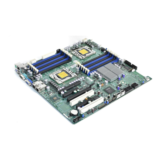
Motherboard Features
2
Memory Installation
Download this manual
X8DT3
X8DTi
X8DT3-F
X8DTi-F
X8DT3-LN4F
X8DTi-LN4F
USER'S MANUAL
Revision 1.0a
Table of
Contents
Previous
Page
Next
Page
1
2
3
4
5
Advertisement
Table of Contents
Need help?
Do you have a question about the X8DT3 and is the answer not in the manual?
Ask a question
Questions and answers
Related Manuals for Super X8DT3
Motherboard Super X9SCi-LN4 User Manual
X9sci-ln4; x9sci-ln4f; x9sca; x9sca-f (107 pages)
Motherboard Super X10SLX-F User Manual
X10slx-f (109 pages)
Motherboard Super X8DTi User Manual
Super motherboard user's manual (98 pages)
Motherboard Super X8DTi-F User Manual
Super motherboard user's manual (98 pages)
Motherboard Super X8DTL-i User Manual
Motherboard (97 pages)
Motherboard Super X8DTL-iF User Manual
Motherboard (97 pages)
Motherboard Super X8DTL-3 User Manual
Motherboard (97 pages)
Motherboard Super X8DT6 User Manual
(99 pages)
Motherboard Super X10SBA User Manual
(99 pages)
Motherboard Super X10DRi User Manual
Motherboard super x10dri; x10dri-t (117 pages)
Motherboard Super X7SPA-L User Manual
(101 pages)
Motherboard Super X8SIE User Manual
(113 pages)
Motherboard Super X10SLL-F User Manual
(111 pages)
Motherboard Super X10SLM-F User Manual
(111 pages)
Motherboard Super PDSMi User Manual
Super pdsmi motherboard (100 pages)
This manual is also suitable for:
X8dti
X8dt3-f
X8dti-f
X8dt3-ln4f
X8dti-ln4f
Table of Contents
Print
Rename the bookmark
Delete bookmark?
Delete from my manuals?
Login
Sign In
OR
Sign in with Facebook
Sign in with Google
Upload manual
Upload from disk
Upload from URL


Need help?
Do you have a question about the X8DT3 and is the answer not in the manual?
Questions and answers