Table of Contents
Advertisement
Quick Links
Advertisement
Table of Contents

Related Manuals for Super X8DT6


Summary of Contents for Super X8DT6
- Page 1 X8DT6 X8DTE X8DT6-F X8DTE-F USER’S MANUAL Revision 1.0b...
- Page 2 Manual Revision 1.0b Release Date: May 5, 2010 Unless you request and receive written permission from Super Micro Computer, Inc., you may not copy any part of this document. Information in this document is subject to change without notice. Other products and companies referred to herein are trademarks or registered trademarks of their respective companies or mark holders.
-
Page 3: About This Manual
QuickPath Interconnect (QPI) Technology, providing the next generation point-to- point system interface to replace the current Front Side Bus. With the 5500/5600 Series Processor platform built in, the X8DT6/X8DT6-F/X8DTE/X8DTE-F offers substantial enhancement in system performance with increased bandwidth and unprecedented scalability optimized for high-end servers, High Performance Com- puting (HPC) systems and intensive applications. - Page 4 X8DT6/X8DT6-F/X8DTE/X8DTE-F User's Manual Warning: Important information given to ensure proper system installation or to prevent damage to the components. Note: Additional Information given to differentiate various models or to ensure correct system setup.
-
Page 5: Contacting Supermicro
Contacting Supermicro Contacting Supermicro Headquarters Address: Super Micro Computer, Inc. 980 Rock Ave. San Jose, CA 95131 U.S.A. Tel: +1 (408) 503-8000 Fax: +1 (408) 503-8008 Email: marketing@supermicro.com (General Information) support@supermicro.com (Technical Support) Web Site: www.supermicro.com Europe Address: Super Micro Computer B.V. -
Page 6: Table Of Contents
Special Features ................... 1-10 PC Health Monitoring ..................1-10 ACPI Features ....................1-11 Power Supply ....................1-12 Super I/O ....................... 1-12 Overview of the Winbond WPCM450 Controller (For X8DT6-F/X8DTE-F Only) ........................1-13 Chapter 2 Installation Static-Sensitive Devices .................. 2-1 Motherboard Installation .................. 2-2 Processor and Heatsink Installation.............. - Page 7 Internal Speaker ..................2-23 Power LED/Speaker ................. 2-23 Wake-On-LAN ..................2-24 Overheat LED/Fan Fail (JOH1) ..............2-24 T-SGPIO Headers ..................2-25 RAIDKey Header (Optional for X8DT6/X8DT6-F only) ......2-25 Power SMB (I C) Connector ..............2-26 IPMB I C SMB ..................2-26 DOM Power Connector ................
- Page 8 X8DT6/X8DT6-F/X8DTE/X8DTE-F User's Manual Starting BIOS Setup Utility ................4-1 How To Change the Confi guration Data ............4-1 Starting the Setup Utility ................. 4-2 Main Setup ...................... 4-2 Advanced Setup Confi gurations..............4-4 Security Settings ................... 4-22 Boot Confi guration ..................4-24 Exit Options ....................
-
Page 9: Chapter 1 Introduction
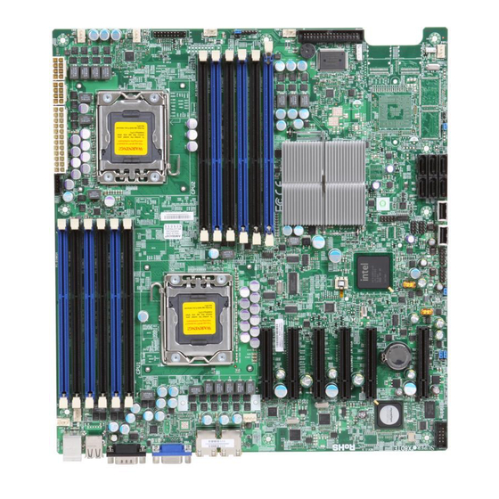
• Four (4) Serial ATA cables (CBL-0044L) (For X8DT6/X8DT6-F) • Six (6) Serial ATA cables (CBL-0044L) (For X8DTE/X8DTE-F) • Two (2) SAS cables for SATA/SAS Backplane (CBL-0097L-02) (For X8DT6/ X8DT6-F) • One (1) I/O backpanel shield (MCP-260-00027-0N) • One (1) Supermicro CD containing drivers and utilities •... - Page 10 X8DT6/X8DT6-F/X8DTE/X8DTE-F User's Manual X8DT6/X8DT6-F Image Note: The drawings and pictures shown in this manual were based on the latest PCB Revision available at the time of publishing of the manual. The motherboard you’ve received may or may not look exactly the same as...
- Page 11 IPMI Dedicated LAN is for X8DT6-F/X8DTE-F only. SAS connectors, jumpers, and the LSI 2008 SATA 2 chip are available on the X8DT6/X8DT6-F only. For SAS RAID confi guration, refer to the LSI User Guide posted on our website @ http://www.supermicro.com/support/manuals/ IPMI 2.0 and the Dedicated LAN (w/KVM support) are available on the...
- Page 12 X8DT6/X8DT6-F/X8DTE/X8DTE-F User's Manual Motherboard Layout FAN5 P1-DIMM3A JPI2C1 JPW2 JPW1 JPW3 P1-DIMM3B FAN1 FAN6 P1-DIMM2A P1-DIMM2B P1-DIMM1A FAN7 P1-DIMM1B CPU2 CPU1 Fan CPU1 FAN2 P2-DIMM1B P2-DIMM1A P2-DIMM2B P2-DIMM2A P2-DIMM3B FAN8/ CPU2 Fan P2-DIMM3A SLOT7 PCI-E 2.0 X8 FAN3 X8DT6/E Series Rev.
- Page 13 System/CPU Fan Headers (Fans 7~8: CPU Fans) Floppy Floppy Disk Drive Connector JIBTN1 RAIDKey for RAID 5 SAS support (optional for X8DT6/X8DT6-F) IPMB I C Header (for an IPMI card) (X8DTE-F/X8DT6-F) PWR LED/Speaker Header (Pins 4~7: Speaker) Front Panel Connector...
- Page 14 Intel 5520 chipset, including: the 5520 (IOH-36D) and the ICH10R (South Bridge). Expansion Slots • Three PCI-E 2.0 x8 slots (Slots 5~7) (X8DT6/X8DT6-F) • Four PCI-E 2.0 x8 slots (Slots 4~7) (X8DTE/X8DTE-F) • One PCI-E 2.0 x4 slot (Slot 3) •...
- Page 15 Up to eight USB 2.0 (Universal Serial Bus) (2 Backpanel USB Ports, 2 Front USB Headers, and 2 Type A Headers) • Super I/O: Winbond W83627HG • IPMI 2.0 with full KVM support (X8DT6-F/X8DTE-F only) (Note 3) Other • Wake-on-LAN (WOL) •...
- Page 16 X8DT6/X8DT6-F/X8DTE/X8DTE-F User's Manual #0-6 #1-6 #1-5 #0-5 #1-4 #0-4 #1-3 #0-3 #1-2 #0-2 #1-1 #0-1 Processor #2 Processor #1 PCI-E X8 Ports #7-8 Intel 5520 PCI-E X8 Ports #5-6 IOH-36D PCI-E X4 Ports #1-2 PCI-E X8 Ports #3-4 Ports PCI-E X8...
-
Page 17: Chipset Overview
Chapter 1: Introduction Chipset Overview Built upon the capability of the Intel 5520 platform, the X8DT6/X8DT6-F/X8DTE/ X8DTE-F motherboard provides the performance and feature set required for dual-processor-based high-end servers optimized for High Performance Comput- ing (HPC), Clustering, and intensive applications. The 5520 platform consists of the 5500/5600 Series (LGA 1366) processor, the 5520 (IO Hub), and the ICH10R (South Bridge). -
Page 18: Special Features
Setup section to change this setting. The default setting is Last State. PC Health Monitoring This section describes the PC health monitoring features of the X8DT6/X8DT6-F/ X8DTE/X8DTE-F. The motherboard has an onboard System Hardware Monitor chip that supports PC health monitoring. An onboard voltage monitor will scan these onboard voltages continuously: CPU1 Vcore/CPU2 Vcore, CPU1 DIMM/ CPU2 DIMM, 1.5V, 3.3Vcc (V), 3.3V SB (V), 12Vcc (V), 5Vin, and Battery Voltage. -
Page 19: Acpi Features
Chapter 1: Introduction environment or used with Supero Doctor II in Linux. Supero Doctor is used to notify the user of certain system events. You can also confi gure Supero Doctor to provide you with warnings when the system/CPU temperatures, voltages and fan speeds go beyond a pre-defi... -
Page 20: Power Supply
Super I/O The disk drive adapter functions of the Super I/O chip include a fl oppy disk drive controller that is compatible with industry standard 82077/765, a data separator, write pre-compensation circuitry, decode logic, data rate selection, a clock genera- tor, drive interface control logic and interrupt and DMA logic. -
Page 21: Overview Of The Winbond Wpcm450 Controller (For X8Dt6-F/X8Dte-F Only)
The WPCM450 interfaces with the host system via a PCI interface to communicate with the Graphics core. It supports USB 2.0 and 1.1 for remote keyboard/mouse/ virtual media emulation. It also provides LPC interface to control Super IO functions. The WPCM450 is connected to the network via an external Ethernet Phy module. - Page 22 X8DT6/X8DT6-F/X8DTE/X8DTE-F User's Manual Notes 1-14...
-
Page 23: Chapter 2 Installation
Chapter 2: Installation Chapter 2 Installation Static-Sensitive Devices Electrostatic Discharge (ESD) can damage electronic com ponents. To prevent dam- age to your system board, it is important to handle it very carefully. The following measures are generally suffi cient to protect your equipment from ESD. Precautions •... -
Page 24: Motherboard Installation
X8DT6/X8DT6-F/X8DTE/X8DTE-F User's Manual Motherboard Installation All motherboards have standard mounting holes to fi t different types of chassis. Make sure that the locations of all the mounting holes for both motherboard and chassis match. Although a chassis may have both plastic and metal mounting fasteners, metal ones are highly recommended because they ground the mother- board to the chassis. -
Page 25: Processor And Heatsink Installation
Chapter 2: Installation Processor and Heatsink Installation When handling the processor package, avoid placing direct pressure on the label area of the fan. Notes: Always connect the power cord last and always remove it before adding, re- moving or changing any hardware components. Make sure that you install the processor into the CPU socket before you install the CPU heatsink. - Page 26 X8DT6/X8DT6-F/X8DTE/X8DTE-F User's Manual After removing the plastic cap, using your thumb and the index fi nger, hold the CPU at the north and south center edges. Align the CPU key, the semi- circle cutout, against the socket key, the notch below the gold color dot on the side of the socket.
-
Page 27: Installing A Cpu Heatsink
Chapter 2: Installation Installing a CPU Heatsink Do not apply any thermal grease to the heatsink or the CPU die because the required amount has already been ap- plied. Screw#1 Screw#2 Place the heatsink on top of the CPU so that the four mounting holes are aligned with those on the retention mechanism. - Page 28 X8DT6/X8DT6-F/X8DTE/X8DTE-F User's Manual Removing the Heatsink Warning: We do not recommend that the CPU or the heatsink be re- moved. However, if you do need to remove the heatsink, please follow the instructions below to uninstall the heatsink and prevent damage to the CPU or other components.
-
Page 29: Memory Installation
Release Note: Notch Release should align with the receptive point X8DT6/E Series Rev. 2.0 on the slot To Install: Insert module vertically and press down until it snaps into place. Pay attention to the alignment notch at To Remove: the bottom. -
Page 30: Memory Support
X8DT6/X8DT6-F/X8DTE/X8DTE-F User's Manual Memory Support The X8DT6/X8DT6-F/X8DTE/X8DTE-F supports up to 192 GB of Registered ECC or up to 48 GB of Unbuffered ECC/Non ECC DDR3 1333 MHz/1066 MHz/800 MHz in 12 DIMMs. Please note that Memory Speed support is also depending on the type of CPU used in the motherboard. - Page 31 Chapter 2: Installation for the motherboards w/5500 Series Processors Memory Support installed RDIMM Population for the Motherboard w/5500 Processors Installed DIMM DIMMs DIMM Type (Reg.= Speeds (in MHz) Ranks per DIMM Slots per Populated Registered) (any combination; Channel per Channel SR=Single Rank, DR=Dual Rank, QR=Quad Rank)
- Page 32 X8DT6/X8DT6-F/X8DTE/X8DTE-F User's Manual • 1.35V DIMMs 1.35V RDIMM Population for the Motherboard w/5600 Processors Installed DIMM DIMMs DIMM Type Speeds (in MHz) Ranks per DIMM Slots per Populated (Reg.=Registered) (any combination; Channel per Channel SR=Single Rank, DR=Dual Rank, QR=Quad Rank) Reg.
-
Page 33: Control Panel Connectors/Io Ports
Back Panel I/O Port Locations and Defi nitions Back Panel Connectors Keyboard (Purple) PS/2 Mouse (Green) Back Panel USB Port 0 Back Panel USB Port 1 IPMI_LAN (X8DT6-F/X8DTE-F only) COM Port 1 (Turquoise) VGA (Blue) Gigabit LAN 1 Gigabit LAN 2 2-11... -
Page 34: Atx Ps/2 Keyboard And Ps/2 Mouse Ports
X8DT6/X8DT6-F/X8DTE/X8DTE-F User's Manual ATX PS/2 Keyboard and PS/2 PS/2 Keyboard/Mouse Pin Mouse Ports Defi nitions PS2 Keyboard PS2 Mouse The ATX PS/2 keyboard and PS/2 Pin# Defi nition Pin# Defi nition mouse are located next to the Back KB Data... -
Page 35: Universal Serial Bus (Usb)
Pin # Defi nition Ground Ground No connection 1. Backpanel USB 0 2. Backpanel USB 1 3. Front Panel USB 2 4. Front Panel USB 3 5. Front Panel USB 4/5 6. Front Panel USB 6/7 X8DT6/E Series Rev. 2.0 2-13... -
Page 36: Serial Ports
X8DT6/X8DT6-F/X8DTE/X8DTE-F User's Manual Serial Ports Serial Ports-COM1/COM2 Pin Defi nitions Two COM connections (COM1 & Pin # Defi nition Pin # Defi nition COM2) are located on the motherboard. COM1 is located on the Backplane IO panel. COM2 is located close to the... -
Page 37: Ethernet Ports
IO backplane. In ad- P2V5SB SGND dition, an IPMI_dedicated_LAN is also TD0+ Act LED located on the X8DT6-F/X8DTE-F to TD0- P3V3SB provide KVM support for IPMI 2.0. All TD1+ Link 100 LED these ports accept RJ45 type cables. -
Page 38: Front Control Panel
X8DT6/X8DT6-F/X8DTE/X8DTE-F User's Manual 2. Front Control Panel JF1 contains header pins for various buttons and indicators that are normally lo- cated on a control panel at the front of the chassis. These connectors are designed specifi cally for use with Supermicro server chassis. See the fi gure below for the descriptions of the various control panel buttons and LED indicators. -
Page 39: Front Control Panel Pin Defi Nitions
Ground A. NMI B. PWR LED Ground Power LED HDD LED NIC1 LED NIC2 LED X8DT6/E Series Rev. 2.0 OH/Fan Fail LED PWR Fail LED Reset Reset Button Ground Power Button Ground... -
Page 40: Hdd Led
X8DT6/X8DT6-F/X8DTE/X8DTE-F User's Manual HDD LED The HDD LED connection is located HDD LED on pins 13 and 14 of JF1. Attach a Pin Defi nitions (JF1) hard drive LED cable here to display Pin# Defi nition disk activities (generated from the ICH10R). -
Page 41: Overheat (Oh)/Fan Fail Led
Ground A. OH/Fan Fail LED B. PWR Supply Fail Ground Power LED HDD LED NIC1 LED NIC2 LED X8DT6/E Series Rev. 2.0 OH/Fan Fail LED PWR Fail LED Reset Reset Button Ground Power Button Ground 2-19... -
Page 42: Reset Button
X8DT6/X8DT6-F/X8DTE/X8DTE-F User's Manual Reset Button Reset Button The Reset Button connection is located Pin Defi nitions (JF1) on pins 3 and 4 of JF1. Attach it to a Pin# Defi nition hardware reset switch on the computer Reset case. Refer to the table on the right for Ground pin defi... -
Page 43: Connecting Cables
Chapter 2: Installation Connecting Cables ATX Power 24-pin Connector Pin Defi nitions Pin# Defi nition Pin # Defi nition Power Connectors +3.3V +3.3V -12V +3.3V A 24-pin main power supply connector(JPW1) and two 8-pin CPU PWR connectors (JPW2/ PS_ON JPW3) are located on the motherboard. These power connectors meet the SSI EPS 12V specifi... -
Page 44: Fan Headers
X8DT6/X8DT6-F/X8DTE/X8DTE-F User's Manual Fan Headers Fan Header This motherboard has six chassis/system Pin Defi nitions fan headers (Fan1 to Fan6) and two CPU Pin# Defi nition fans (Fan7/Fan8) on the motherboard. All Ground these 4-pin fans headers are backward +12V compatible with the traditional 3-pin fans. -
Page 45: Internal Speaker
FAN2 P2-DIMM1B P2-DIMM1A P2-DIMM2B P2-DIMM2A P2-DIMM3B FAN8/ CPU2 Fan P2-DIMM3A SLOT7 PCI-E 2.0 X8 FAN3 X8DT6/E Series Rev. 2.0 SLOT6 PCI-E 2.0 X8 JPL1 SLOT5 PCI-E 2.0 X8 SLOT4 PCI-E 2.0 X8 LED1 JPL2 SAS0~3 SLOT3 PCI-E 2.0 X4 SAS4~7... -
Page 46: Wake-On-Lan
X8DT6/X8DT6-F/X8DTE/X8DTE-F User's Manual Wake-On-LAN Wake-On-LAN Pin Defi nitions The Wake-On-LAN header is located Pin# Defi nition at JWOL on the motherboard. You +5V Standby must also have a LAN card with a Ground Wake-On-LAN connector and a cable Wake-up to use this feature. See the table on the right for pin defi... -
Page 47: T-Sgpio Headers
A. T-SGPIO-1 FAN5 B. T-SGPIO-2 P1-DIMM3A JPI2C1 JPW2 JPW1 JPW3 P1-DIMM3B FAN1 FAN6 C. RAIDKey Connection P1-DIMM2A P1-DIMM2B (Optional for X8DT6/ P1-DIMM1A FAN7 P1-DIMM1B CPU2 CPU1 Fan X8DT6-F only) CPU1 FAN2 P2-DIMM1B P2-DIMM1A P2-DIMM2B P2-DIMM2A P2-DIMM3B FAN8/... -
Page 48: Power Smb
X8DT6/X8DT6-F/X8DTE/X8DTE-F User's Manual Power SMB (I C) Connector PWR SMB Pin Defi nitions Power System Management Bus (I Pin# Defi nition Connector (JPI C1) monitors power Clock supply, fan and system temperatures. Data See the table on the right for pin PWR Fail defi... -
Page 49: Dom Power Connector
FAN2 P2-DIMM1B P2-DIMM1A P2-DIMM2B P2-DIMM2A P2-DIMM3B FAN8/ CPU2 Fan P2-DIMM3A SLOT7 PCI-E 2.0 X8 FAN3 X8DT6/E Series Rev. 2.0 SLOT6 PCI-E 2.0 X8 JPL1 SLOT5 PCI-E 2.0 X8 SLOT4 PCI-E 2.0 X8 LED1 JPL2 SAS0~3 SLOT3 PCI-E 2.0 X4 SAS4~7... -
Page 50: Jumper Settings
Note: For information on LSI SAS RAID confi guration, please refer to the LSI MegaRAID User's Guide @ http://www.supermicro.com/support/ manuals/. FAN5 P1-DIMM3A JPI2C1 JPW2 JPW1 JPW3 P1-DIMM3B FAN1 FAN6 P1-DIMM2A P1-DIMM2B A. SAS Enable (X8DT6/ P1-DIMM1A FAN7 P1-DIMM1B CPU2 CPU1 Fan X8DT6-F CPU1 FAN2 P2-DIMM1B P2-DIMM1A P2-DIMM2B P2-DIMM2A P2-DIMM3B... -
Page 51: Cmos Clear
FAN2 P2-DIMM1B P2-DIMM1A P2-DIMM2B P2-DIMM2A P2-DIMM3B FAN8/ CPU2 Fan P2-DIMM3A SLOT7 PCI-E 2.0 X8 FAN3 X8DT6/E Series Rev. 2.0 SLOT6 PCI-E 2.0 X8 JPL1 SLOT5 PCI-E 2.0 X8 SLOT4 PCI-E 2.0 X8 LED1 JPL2 SAS0~3 SLOT3 PCI-E 2.0 X4 SAS4~7... -
Page 52: I 2 C Bus To Pci-Exp. Slots
X8DT6/X8DT6-F/X8DTE/X8DTE-F User's Manual C Bus to PCI-Exp. Slots C to PCI-Exp Jumpers JI C1 and JI C2 allow you to Jumper Settings connect the System Management Bus Jumper Setting Defi nition C) to PCI-Express slots. The default Enabled setting is Open to disable the connec- Disabled (Default) tion. -
Page 53: Glan Enable/Disable
FAN2 P2-DIMM1B P2-DIMM1A P2-DIMM2B P2-DIMM2A P2-DIMM3B FAN8/ CPU2 Fan P2-DIMM3A SLOT7 PCI-E 2.0 X8 FAN3 X8DT6/E Series Rev. 2.0 SLOT6 PCI-E 2.0 X8 JPL1 SLOT5 PCI-E 2.0 X8 SLOT4 PCI-E 2.0 X8 LED1 JPL2 SAS0~3 SLOT3 PCI-E 2.0 X4 SAS4~7... -
Page 54: Onboard Led Indicators
In addition to LAN 1/LAN 2, an IPMI Dedi- cated LAN is also located on the IO Back- IPMI LAN Link LED (Left) & Activity LED (Right) plane of the X8DT6-F/X8DTE-F. The amber Color Status Defi nition LED on the right indicates activity, while the... -
Page 55: Sas Heartbeat Led Indicator
FAN2 P2-DIMM1B P2-DIMM1A P2-DIMM2B P2-DIMM2A P2-DIMM3B FAN8/ CPU2 Fan P2-DIMM3A SLOT7 PCI-E 2.0 X8 FAN3 X8DT6/E Series Rev. 2.0 SLOT6 PCI-E 2.0 X8 JPL1 SLOT5 PCI-E 2.0 X8 SLOT4 PCI-E 2.0 X8 LED1 JPL2 SAS0~3 SLOT3 PCI-E 2.0 X4 SAS4~7... -
Page 56: Onboard Power Led
X8DT6/X8DT6-F/X8DTE/X8DTE-F User's Manual Onboard Power LED Onboard PWR LED (LE1) An Onboard Power LED is located at LE1 Settings on the motherboard. When this LED is lit, LED Color Defi nition the system is on. Be sure to turn off the... -
Page 57: Floppy Drive, Serial Ata And Sas Connections
Floppy Connector Ground Motor Enable The fl oppy connector is located next Ground Drive Select B to the Super I/O chip on the mother- Ground Drive Select B board. See the table on the right for Ground Motor Enable pin defi nitions. -
Page 58: Serial Ata Ports
See the table on the right for pin RX_N defi nitions. RX_P Ground SAS Ports (X8DT6/X8DT6-F only) SAS Ports 0~3, 4~7, located at JSM1/ JSM2, provide Serial-Attached SCSI connections on the X8DT6/X8DT6-F. See the layout below for SAS port locations. -
Page 59: Chapter 3 Troubleshooting
Chapter 3: Troubleshooting Chapter 3 Troubleshooting Troubleshooting Procedures Use the following procedures to troubleshoot your system. If you have followed all of the procedures below and still need assistance, refer to the ‘Technical Support Procedures’ and/or ‘Returning Merchandise for Service’ section(s) in this chapter. Note: Always disconnect the power cord before adding, changing or installing any hardware components. -
Page 60: No Video
X8DT6/X8DT6-F/X8DTE/X8DTE-F User's Manual No Video If the power is on but you have no video, remove all the add-on cards and cables. Use the speaker to determine if any beep codes exist. Refer to Appendix A for details on beep codes. -
Page 61: Technical Support Procedures
Question: What are the various types of memory that my motherboard can support? Answer: The X8DT6/X8DT6-F/X8DTE/X8DTE-F has 12 240-pin DIMM slots that support up to 192 GB of DDR3 Registered ECC or up to 48 GB of Unbuffered ECC/ Non ECC 1333 MHz/1066 MHz/800 MHz SDRAM modules. It is strongly recom- mended that you do not mix memory modules of different speeds and sizes. -
Page 62: Returning Merchandise For Service
X8DT6/X8DT6-F/X8DTE/X8DTE-F User's Manual Question: How do I update my BIOS? Answer: It is recommended that you do not upgrade your BIOS if you are not experiencing any problems with your system. Updated BIOS fi les are located on our web site at http://www.supermicro.com/support/bios/. Please check our BIOS warning message and the information on how to update your BIOS on our web site. -
Page 63: Chapter 4 Bios
BIOS Introduction This chapter describes the AMI BIOS Setup Utility for the X8DT6/X8DT6-F/X8DTE/ X8DTE-F. The AMI ROM BIOS is stored in a Flash EEPROM and can be easily updated. This chapter describes the basic navigation of the AMI BIOS Setup Utility setup screens. -
Page 64: Starting The Setup Utility
X8DT6/X8DT6-F/X8DTE/X8DTE-F User’s Manual Starting the Setup Utility Normally, the only visible Power-On Self-Test (POST) routine is the memory test. As the memory is being tested, press the <Delete> key to enter the main menu of the AMI BIOS Setup Utility. From the main menu, you can access the other setup screens. - Page 65 Chapter 4: AMI BIOS Supermicro X8DT6/X8DTE BIOS Build Version: This item displays the BIOS revision used in your system. BIOS Build Date: This item displays the date when this BIOS was completed. AMI BIOS Core Version: This item displays the revision number of the AMI BIOS Core upon which your BIOS was built.
-
Page 66: Boot Features
X8DT6/X8DT6-F/X8DTE/X8DTE-F User’s Manual Advanced Setup Confi gurations Use the arrow keys to select Boot Setup and hit <Enter> to access the submenu items: Boot Features Quick Boot If Enabled, this option will skip certain tests during POST to reduce the time needed for system boot. -
Page 67: Processor And Clock Options
Chapter 4: AMI BIOS Hit 'Del' Message Display This feature displays "Press DEL to run Setup" during POST. The options are Enabled and Disabled. Interrupt 19 Capture Interrupt 19 is the software interrupt that handles the boot disk function. When this item is set to Enabled, the ROM BIOS of the host adaptors will "capture"... - Page 68 X8DT6/X8DT6-F/X8DTE/X8DTE-F User’s Manual C1E Support Select Enabled to enable Enhanced Halt State support. C1E signifi cantly reduces the CPU's power consumption by reducing the CPU's clock cycle and voltage during a "Halt State." The options are Disabled and Enabled. Hardware Prefetcher (Available when supported by the CPU)
-
Page 69: Advanced Chipset Control
Chapter 4: AMI BIOS Active Processor Cores Set to Enabled to use a processor's Second Core and beyond. (Please refer to Intel's web site for more information.) The options are All, 1 and 2. Intel® Speed_Step™ Technology EIST (Enhanced Intel SpeedStep Technology) allows the system to automatically adjust processor voltage and core frequency in an effort to reduce power consump- tion and heat dissipation. - Page 70 X8DT6/X8DT6-F/X8DTE/X8DTE-F User’s Manual CPU Bridge Confi guration QPI (Quick_Path Interface) Links Speed This feature selects QPI's data transfer speed. The options are Slow-mode, and Full Speed. QPI Frequency This selects the desired QPI frequency. The options are Auto, 4.800 GT, 5.866GT, 6.400 GT.
- Page 71 Chapter 4: AMI BIOS Hysteresis Temperature (Closed Loop Only) Temperature Hysteresis is the temperature lag (in degrees Celsius) after the preset DIMM temperature threshold is reached before Closed Loop Throt- tling begins. The options are Disabled, 1.5 C, 3.0 C, and 6.0 Guardband Temperature (Closed Loop Only) This is the temperature applied to the DIMM temperature threshold.
- Page 72 X8DT6/X8DT6-F/X8DTE/X8DTE-F User’s Manual Crystal Beach/DCA (Direct Cache Access) This feature works in conjunction with the Intel I/O AT (Acceleration Technology) to accelerate the performance of the TOE device. When this feature set to Enabled, it will enhance overall system performance by providing direct cache access for data transferring.
- Page 73 Chapter 4: AMI BIOS Hand-Off support. When enabled, the EHCI Interface will be changed from the BIOS- controlled to the OS-controlled. The options are Disabled and Enabled. IDE/SATA Confi guration When this submenu is selected, the AMI BIOS automatically detects the presence of the IDE devices and displays the following items: SATA#1 Confi...
- Page 74 X8DT6/X8DT6-F/X8DTE/X8DTE-F User’s Manual Block (Multi-Sector Transfer) Block Mode boosts the IDE drive performance by increasing the amount of data transferred. Only 512 bytes of data can be transferred per interrupt if Block Mode is not used. Block Mode allows transfers of up to 64 KB per interrupt. Select Disabled to allow data to be transferred from and to the device one sector at a time.
- Page 75 Chapter 4: AMI BIOS Select MWDMA2 to allow the BIOS to use Multi-Word DMA mode 2. It has a data transfer rate of 16.6 MBs. Select UDMA0 to allow the BIOS to use Ultra DMA mode 0. It has a data transfer rate of 16.6 MBs.
- Page 76 Select Enabled to enable the onboard LAN1/LAN2 PXE Option ROMs in order to boot the computer using a network interface. The options are Enabled and Disabled. Super IO Device Confi guration Onboard Floppy Controller Select Enable to enable the onboard Floppy Controller. The options are Enabled and Disabled.
- Page 77 Chapter 4: AMI BIOS Port1 are Disabled, 3F8/IRQ4, 3E8/IRQ4, 2E8/IRQ3. The options for Serial Port2 are Disabled, 2F8/IRQ3, 3E8/IRQ4, and 2E8/IRQ3. Serial Port 2 Mode Use this feature to confi gure Serial Port 2 mode. The options are Normal, IrDA and ASK IR.
-
Page 78: System Health Monitor
X8DT6/X8DT6-F/X8DTE/X8DTE-F User’s Manual Terminal Type This feature allows the user to select the target terminal type for Console Redi- rection. The options are ANSI, VT100, and VT-UTF8. VT-UTF8 Combo Key Support A terminal keyboard defi nition that provides a way to send commands from a remote console. - Page 79 Chapter 4: AMI BIOS CPU Temperature/System Temperature This feature displays current temperature readings for the CPU and the System. The following items will be displayed for your reference only: CPU Temperature The CPU thermal technology that reports absolute temperatures (Celsius/Fahr- enheit) has been upgraded to a more advanced feature by Intel in its newer processors.
- Page 80 (12V). The Options are: Disabled (full-speed), 4-pin (Server), 4-pin (Workstation), 4-pin (Quiet) and , 4-pin (Super Quiet). Fan1 ~ Fan 8 Reading This feature displays the fan speed readings from fan interfaces Fan1 through Fan8.
-
Page 81: View Bmc System Event Log
Chapter 4: AMI BIOS Headless Mode When this feature is enabled, the system will function without a keyboard, monitor or mouse attached The options are Enabled and Disabled. High Performance Event Timer Select Enabled to activate the High Performance Event Timer (HPET) that produces periodic interrupts at a much higher frequency than a Real-time Clock (RTC) does in synchronizing multimedia streams, providing smooth playback and reducing the de- pendency on other timestamp calculation devices, such as an x86 RDTSC Instruc-... - Page 82 X8DT6/X8DT6-F/X8DTE/X8DTE-F User’s Manual • Event Sensor Type • Event Sensor Number, • Event Dir Type • Event Data. Clear BMC System Event Log Select OK and press the <Enter> key to clear the BMC system log. Select Cancel to keep the BMC System log. The options are OK and Cancel.
- Page 83 Chapter 4: AMI BIOS administrator). Only clients with an IP Address within the pre-determined range of addresses will be allowed access to the network. A static IP Address that is assigned to a device is retained until it is manually re-assigned a different address, or re-confi...
-
Page 84: Dmi Event Log
X8DT6/X8DT6-F/X8DTE/X8DTE-F User’s Manual Gateway Address Confi guration This option allows to user to enter the gateway address for this machine. This should be in decimal and in dotted quad form (i.e., 192.168.10.253). The value of each three-digit number separated by dots should not exceed 255. - Page 85 Chapter 4: AMI BIOS Supervisor Password This item indicates if a Supervisor password has been entered for the system. "Not Installed" means a Supervisor password has not been used. User Password This item indicates if a user password has been entered for the system. "Not In- stalled"...
-
Page 86: Boot Device Priority
X8DT6/X8DT6-F/X8DTE/X8DTE-F User’s Manual Password Check This item allows you to check a password after it has been entered. The options are Setup and Always. Boot Sector Virus Protection When Enabled, the AMI BIOS displays a warning when any program (or virus) is- sues a Disk Format command or attempts to write to the boot sector of the hard disk drive. -
Page 87: Removable Drives
Chapter 4: AMI BIOS Removable Drives This feature allows the user to specify the boot sequence from available Removable Drives. The settings are 1st boot device, 2nd boot device, and Disabled. • 1st Drive - 1st Floppy Drive • 2nd Drive - [USB: XXXXXXXXX] CD/DVD Drives This feature allows the user to specify the boot sequence from available CD/DVD Drives (i.e., 1st Drive, 2nd Drive, etc). -
Page 88: Exit Options
X8DT6/X8DT6-F/X8DTE/X8DTE-F User’s Manual Exit Options Select the Exit tab from the AMI BIOS Setup Utility screen to enter the Exit BIOS Setup screen. Save Changes and Exit After you have completed system confi guration changes, select this option and press <Enter> to reboot the compute so that the new system confi guration settings can take effect. -
Page 89: Bios Recovery
A user can download the BIOS image into a USB fl ash device, and name the fi le "SUPER.ROM" for the recovery process to load the fi le. A USB fl ash device such as a USB Flash Drive, a USB CDROM or a USB CDRW device can be used for this purpose, Insert the USB device that contains the new BIOS image (the ROM fi... -
Page 90: Boot Sector Recovery From An Ide Cd-Rom
BIOS image fi le is loaded from a CD-ROM. Use a CD-R or CD-RW drive to burn a CD with the BIOS image fi le in it, and name the fi le "SUPER. ROM" for the recovery process to load the fi le. - Page 91 Chapter 4: AMI BIOS 4. Power on your system and click the <Connect> button in the Hyper Terminal. The terminal screen will display the following messages. Press <SpaceBar> to update BIOS. Confirm update BIOS? (y/n) y Begin remote BIOS flash? (y/n) y Starting remote flash.
- Page 92 X8DT6/X8DT6-F/X8DTE/X8DTE-F User’s Manual Once the ROM fi le extraction is completed, the message: "New BIOS re- ceived OK" will display. 8. Once remote BIOS fl ash is completed, the system will reboot. Note: AMIBIOS Serial Flash will work with any terminal communications program that supports VT-100 and XModem protocols, including protocols designed for GNU/LINUX &...
-
Page 93: Appendix A Bios Error Beep Codes
Appendix A: BIOS POST Error Codes Appendix A BIOS Error Beep Codes During the POST (Power-On Self-Test) routines, which are performed each time the system is powered on, errors may occur. Non-fatal errors are those which, in most cases, allow the system to continue the boot-up process. - Page 94 X8DT6/X8DT6-F/X8DTE/X8DTE-F User's Manual Notes...
-
Page 95: Appendix B Software Installation Instructions
Appendix B: Software Installation Instructions Appendix B Software Installation Instructions B-1 Installing Software Programs After you've installed the Windows Operating System, a screen as shown below will appear. You are ready to install software programs and drivers that have not yet been installed. - Page 96 X8DT6/X8DT6-F/X8DTE/X8DTE-F User's Manual B-2 Confi guring Supero Doctor III The Supero Doctor III program is a Web-based management tool that supports remote management capability. It includes Remote and Local Management tools. The local management is called the SD III Client. The Supero Doctor III program included on the CDROM that came with your motherboard allows you to monitor the environment and operations of your system.
- Page 97 Appendix B: Software Installation Instructions Supero Doctor III Interface Display Screen-II (Remote Control) Note: SD III Software Revision 1.0 can be downloaded from our Web site at: ftp://ftp.supermicro.com/utility/Supero_Doctor_III/. You can also download SDIII User's Guide at: http://www.supermicro.com/PRODUCT/ Manuals/SDIII/UserGuide.pdf. For Linux, we will still recommend that you use Supero Doctor II.
- Page 98 X8DT6/X8DT6-F/X8DTE/X8DTE-F User's Manual Notes...
- Page 99 (Disclaimer Continued) The products sold by Supermicro are not intended for and will not be used in life support systems, medical equipment, nuclear facilities or systems, aircraft, aircraft devices, aircraft/emergency communication devices or other critical systems whose failure to perform be reasonably expected to result in signifi cant injury or loss of life or catastrophic property damage.
Need help?
Do you have a question about the X8DT6 and is the answer not in the manual?
Questions and answers