Table of Contents
Advertisement
Advertisement
Table of Contents

Related Manuals for Kenmore 795.78542.801


Summary of Contents for Kenmore 795.78542.801
- Page 1 SERVICE MANUAL CAUTION BEFORE SERVICING THE UNIT, READ THE SAFETY PRECAUTIONS IN THIS MANUAL. Model #s: 795.78542.801 795.78543.801 795.78544.801 795.78546.801 795.78549.801 795.78552.801 795.78553.801 795.78554.801 795.78556.801 795.78559.801 P/No. MFL47912405 (Last Revision: March. 10. 2008)
-
Page 2: Table Of Contents
CONTENTS SAFETY PRECAUTIONS ............................... 2 1. SPECIFICATIONS................................3 2. PARTS IDENTIFICATION ..............................4 3. DISASSEMBLY................................5-12 DOOR ....................................5-8 TO REMOVE THE DISPENSER ............................8 FAN AND FAN MOTOR ..............................8 DEFROST CONTROL ASSEMBLY ............................ 9 LAMP ....................................9 CONTROL BOX-REFRIGERATOR ............................ 9 MULTI DUCT .................................. -
Page 3: Specifications
1. SPECIFICATIONS 1-1 DISCONNECT POWER CORD BEFORE 1-7 REPLACEMENT PARTS SERVICING 25 cuft 795. 78542.801 795. 78552.801 IMPORTANT – RECONNECT ALL 795. 78543.801 795. 78553.801 795. 78544.801 795. 78554.801 GROUNDING DEVICES 795. 78546.801 795. 78556.801 795. 78549.801 795. 78559.801 All parts of this appliance capable of conducting electrical Relay EBG44308701 current are grounded. -
Page 4: Dimensions
1-9 DIMENSIONS Description 795.785** Depth w/ Handles 34 1/4 in. Depth w/o Handles 31 3/4 in. Depth w/o Door 27 7/8 in. Depth (Total with Door Open) 46 1/2 in. Height to Top of Case 68 3/8 in. Height to Top of Door Hinge 69 3/4 in. -
Page 5: Parts Identification
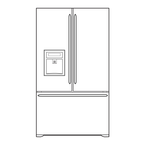
2. PARTS IDENTIFICATION Water Filter Dairy Bin Refrigerator Light Utility/Egg Box Refrigerator Shelves Modular Door Bins Door Bins Humidity Bottle Holder Controlled (795.7855** Crisper Models Only) Modular Water Tank Door Bins Cover Wide Pantry Drawer Pull-Out Drawer Adjusta Cube Ice Maker Ice Bin Tilt-Out Door Basket... -
Page 6: Disassembly
3. DISASSEMBLY 3-1 REMOVING AND REPLACING REFRIGERATOR DOORS To remove the left refrigerator door: To remove the right refrigerator door: IMPORTANT: CAUTION : WARNING Explosion Hazard IMPORTANT: - 6 -... -
Page 7: Door
3-2 DOOR Door Gasket Replacement 1. Insert gasket bracket clips Door Gasket Removal 1) Insert gasket bracket edge beneath door frame edge. 1. Remove door frame cover 2) Turn upper gasket bracket spring so that the spring Starting at top of cover and working down, snap cover ends are in the door channel. -
Page 8: To Remove The Dispenser
2) Press gasket into channels on the three remaining 2. Pry off cover dispenser. sides of door. Figure 6 Figure 9 3. Replace door frame cover Starting at top of cover and working down, snap cover Disconnect wire harness. back into door. 3. -
Page 9: Fan And Fan Motor
3-5 FAN AND FAN MOTOR 4. Make sure the bulbs are cool to the touch. Turn bulbs counterclockwise to remove. 1. Remove the freezer shelf. (If your refrigerator has an 5. Assemble in reverse order by snapping the Lamp Cover icemaker, remove the icemaker first) in, engaging the rear tabs followed by the front tabs. -
Page 10: How To Remove And Reinstall The Pullout Drawer
3-10 HOW TO REMOVE AND REINSTALL THE PULLOUT DRAWER 3-10-1 FOLLOW STEPS TO REMOVE Step 1) Open the freezer door. Step 2) Remove the lower basket. Step 3) Remove the two screws from the guide rails (one Step 4) Lift the freezer door up to unhook it from the rail from each side). - Page 11 3-10-2 FOLLOW STEPS TO REINSTALL Step 1) Reinstall the right side gear into the clip. Step 2) Insert the rail into the right side gear. Gears do not Step 3) Insert the rail into the left side gear, and insert the need to be perpendicular to each other.
- Page 12 3-10-3 PULL OUT DRAWER To separate the drawer, push the front left and right hooks in direction to pull up and remove. Then gently lift the gear part of rear left and right side of the drawer and pull it out in direction.
-
Page 13: Adjustment
4. ADJUSTMENT 4-1 COMPRESSOR 4-1-1 Role 4-2-3 TSD-Applied circuit diagram Starting method for the motor The compressor intakes low temperature and low pressure gas from the evaporator of the refrigerator and compresses this gas to high-temperature and high-pressure gas. It then ELECTRICAL AND DIMENSION DIAGRAM delivers the gas to the condenser. -
Page 14: Olp (Overload Protector)
4-3 OLP (OVERLOAD PROTECTOR) 4-3-1 Definition of OLP (1) OLP (OVERLOAD PROTECTOR) is attached to the Compressor and protects the Motor by opening the circuit to the Motor if the temperature rises and activating the bimetal spring in the OLP. (2) When high current flows to the Compressor motor, the Bimetal works by heating the heater inside the OLP, and the OLP protects the Motor by cutting off the... -
Page 15: Circuit Diagram
5. CIRCUIT DIAGRAM CIRCUIT DIAGRAMS - 15 -... -
Page 16: Compressor And Electric Components
6-1 COMPRESSOR AND ELECTRIC COMPONENTS (Rated voltage Remove TSD-Starter Power source. ±10%)? from compressor and measure voltage between terminal C of compressor and terminal 5 or 6 of TSD. OLP disconnected? No voltage. Replace OLP. Check connection condition. Reconnect. Applied voltage isn't Advise customer that in acceptable range. - Page 17 6-2 TSD AND OLP Normal operation of Separate TSD-Starter Observation value is compressor is from compressor and 120V /60Hz : 6.8Ω±30% measure resistance impossible or poor. between No. 5 and 6 of TSD-Starter with a Tester. (Figure 20) Replace TSD- The resistance value Starter.
-
Page 18: Other Electrical Components
6-3 OTHER ELECTRICAL COMPONENTS Not cooling at all Check for open short or Compressor Cause incorrect resistance readings doesn't run. in the following components a. Starting devices Short, open, or broken. Poor contact b. OLP or shorted. Coil open or shorted. c. -
Page 19: Service Diagnosis Chart
6-4 SERVICE DIAGNOSIS CHART COMPLAINT POINTS TO BE CHECKED REMEDY No Cooling. • Is the power cord unplugged from the outlet? • Plug into the outlet. • Check if the power switch is set to OFF. • Set the switch to ON. •... -
Page 20: Refrigeration Cycle
6-5 REFRIGERATION CYCLE Troubleshooting Chart TEMPERATURE STATE OF STATE OF THE CAUSE REMARKS OF THE THE UNIT EVAPORATOR COMPRESSOR PARTIAL Freezer Low flowing sound of A little higher • Refrigerant level is low due LEAKAGE compartment and refrigerant is heard and than ambient •... - Page 21 6-5-1 SEALED SYSTEM DIAGNOSIS Not Cooling Complaint All components operating, No airflow problems, Not frosted up as a defrost problem problem has been isolated to sealed system area Frost None Partial Pattern? Equalization Equalization Test Test Very Fast Very Slow Very Slow Very Fast Fast...
-
Page 22: Operation Principle And Repair Method Of Icemaker
7. OPERATION PRINCIPLE AND REPAIR METHOD OF ICEMAKER 7-1 OPERATION PRINCIPLE 7-1-1 Operation Principle of Icemaker Power On Start Position Start Position Icemaking Mode Harvest Mode Fill Icemaking Mode Park Position Fill Key Test Mode Harvest Fill Icemaking 1. Turning the icemaker stop switch off (O) stops the icemaking function. 2. - Page 23 7-2 ICE MAKER FUNCTIONS 7-2-1 Start Position 1. After POWER OFF or power outage, check the EJECTOR's position with MICOM initialization to restart. 2. How to check if it is in place: - Check HIGH/LOW signals from HALL SENSOR in MICOM PIN. 3.
- Page 24 7-2-4 Fill/Park Position 1. Once a normal harvest mode has been completed, the water solenoid will be activated. 2. The amount of water is adjusted by pressing the fill key repeatedly. This changes the time allowed for fill as illustrated in the table below.
- Page 25 7-2-5 Function TEST 1. This is a compulsory operation for test, service, cleaning, etc. It is operated by pressing and holding the fill key for 3 seconds. 2. The test works only in the icemaking mode. It cannot be entered from the harvest or fill mode. (If there is an ERROR, it can be checked only in the test mode.) 3.
-
Page 26: Description Of Function And Circuit Of Micom
8. DESCRIPTION OF FUNCTION & CIRCUIT OF MICOM 8-1 FUNCTION 8-1-1 Function 1. When the appliance is plugged in, it is set to 37 for Refrigerator and 0 for freezer. You can adjust the Refrigerator and the Freezer control temperature by pressing the ADJUST button. 2. - Page 27 8-1-6 CONTROL OF FREEZER FAN MOTOR 1. Freezer fan motor has high and standard speeds. 2. High speed is used at power-up, for Ultra Ice, and when refrigerator is overloaded. Standard speeds is used for general purposes. 3. To improve cooling speed, the RPM of the freezer fan motor change from normal speed to high. 4.
- Page 28 8-1-10 Buzzer Sound When the button on the front Display is pushed, a Ding~ Dong~ sound is produced. 8-1-11 Defrost cycle 1. A defrost cycle will be initiated after 4 hours of accumulated compressor run time after the initial power up or a power failure.
- Page 29 8-1-13 Automatic Diagnosis Function 1. Automatic diagnosis makes servicing the refrigerator easy. 2. When an error occurs, the buttons will not operate; but the tones. such as ding. will sound. 3. When the error CODE removes the sign, it returns to normal operation (RESET). 4.
- Page 30 8-1-14 TEST Mode 1. The test mode allows checking the PCB and the function of the product as well as finding out the defective part in case of an error. 2. The test mode is operated by pressing test buttons at main PCB controller. 3.
- Page 31 8-2 PCB FUNCTION 8-2-1 Power Circuit The secondary part of the TRANSFORMER is composed of the power supply for the display, the BLDC FAN Motor drive (15.5 V), the relay drive (12 Vdc) and the MICOM and IC (5 Vdc). The voltage for each part is as follows: PART VA 1...
- Page 32 8-2-2 Oscillation Circuit This circuit generates the base clock for calculating time and the synchro clock for transmitting data from and to the inside logic elements of the IC1 (MICOM). Be sure to use specified replacement parts, since calculating time by the IC1 may be changed.
- Page 33 8-2-2 Load / Buzzer Drive & Open Door Detection Circuit 1. Load Drive Condition Check Circuit Pin Number Pin Number Output Voltage Compressor Con1 pin1 Con1 pin3 115 VAC Defrost heater Con2 pin1 Con1 pin3 115 VAC F,R-lamp Con2, pins 3 and 5 Con1 pin3 115 VAC Water valve...
- Page 34 3. Open Door Detection Circuit Check 8-2-3 Temperature Sensor Circuit The upper circuit reads refrigerator temperature, freezer temperature, and defrost sensor temperature for defrosting and the indoor temperature for compensating for the surrounding temperature into MICOM. Opening or short state of each temperature sensor are as follows: SENSOR CHECK POINT NORMAL (-30°C ~ 50°C)
- Page 35 8-2-4 Refrigeration Compartment Stepping Motor Damper Circuit A reversible DC motor is used to open and close the damper. To open the damper, push test button once. To close the damper, push test button twice. 8-3 RESISTANCE SPECIFICATION OF SENSOR RESISTANCE OF FREEZER RESISTANCE OF REFRIGERATOR &...
-
Page 36: Troubleshooting
8-3 TROUBLESHOOTING PROBLEM INDICATED BY CHECK CHECKING METHOD CAUSE SOLUTION POWER 1. The whole 1. FREEZER/ Check if POWER SOURCE is Use boosting TRANS. SOURCE is DISPLAY LCD is REFRIGERATOR. FREEZER/REFRIGERA poor. poor. off. TOR DOOR IS OPEN and check display. 2. - Page 37 PROBLEM INDICATED BY CHECK CHECKING METHOD CAUSE SOLUTION COOLING is 1. If FREEZER Check is FREEZER Make sure the DOOR poor. REFRIGERATOR TEMPERATURE is TEMPERATURE is too isattached. TEMPERATURE normal. low. is too low. 2. If amount of cool air Make sure that the FAN MOTOR is poor.
- Page 38 8-4 MAIN PWB ASSEMBLY AND PARTS LIST 8-4-1 Main PWB Assembly Connector4 Connector6 Connector5 Test Switch Connector1 Connector3 Connector2 - 38 -...
-
Page 39: Icemaker Parts
For Sears professional installation of home appliances 795.78542.801 and items like garage door openers and water heaters. 795.78543.801 All repair parts listed are available 795.78544.801... - Page 40 CASE PARTS CAUTION: Use the part number to order the part, not the position number. 607A 207B 626A 402A 624D 103B 624C 103A 271A 410A 207A 271B 409D 624A 406D 501F 402A 120A 271C 610D 282F 503D 410G 610B 271D 145A 610A 500A...
- Page 41 CASE PARTS LOC No. 785*3 785*6 785*2 785*9 785*4 Description 103A 3650JA2061W 3650JA2061W 3650JA2061B 3650JA2113N 3650JA2061V Handle,Rear 103B 3650JA2061X 3650JA2061X 3650JA2061A 3650JA2113P 3650JA2061U Handle,Rear 103C 3550JJ0008L 3550JJ0008L 3550JJ0008A 3550JJ0008C 3550JJ0008B Cover,Lower 105A 5251JA3003D 5251JA3003D 5251JA3003D 5251JA3003D 5251JA3003D Tube Ass embly,Drain 106A 4779JJ2001B 4779JJ2001B...
- Page 42 CASE PARTS LOC No. 785*3 785*6 785*2 785*9 785*4 Description 4000W4A003A 4000W4A003A 4000W4A003A 4000W4A003A 4000W4A003A Screw,Customized 1STZJA3004G 1STZJA3004G 1STZJA3004D 1STZJA3004Q 1STZJA3004J Screw,Customized 1BZZJA2002A 1BZZJA2002A 1BZZJA2002A 1BZZJA2002A 1BZZJA2002A Bolt,Common 4J00415D 4J00415D 4J00415D 4J00415D 4J00415D Screw ,Customized 4J00415D 4J00415D 4J00415D 4J00415D 4J00415D Screw,Customized 4J00415D 4J00415D...
- Page 43 REFRIGERATOR PARTS CAUTION: Use the part number to order the part, not the position number. 141A 147C 141B 147A 141A 141B 141C 141A 141B 141C 140A 141C 141E 142B 141D 161C 142A 161B 154A 151B 151A 146E 161A 145E 162B 145D 162A : on some models...
-
Page 44: Door Parts
REFRIGERATOR PARTS LOC No. 785*3 785*6 785*2 785*4 Description 140A AHT36706707 AHT36706707 AHT36706707 AHT36706707 Shelf Assembly, Refrigerator 141A AHT36764303 AHT36764303 AHT36764303 AHT36764303 Shelf Assembly,Refrigerator 141B AHT36968103 AHT36968103 AHT36968103 AHT36968103 Shelf,Refrigerator 141C 5027JJ2012F 5027JJ2012F 5027JJ2012F 5027JJ2012F Shelf Assembly,Net 141D 4890JJ1007Y 4890JJ1007Y 4890JJ1007Y 4890JJ1007Y Cover,Glass... - Page 45 DOOR PARTS CAUTION: Use the part number to order the part, not the position number. 230B 241A 230A 241C 241B 231B 233B 233C 233D 233A 231A 241D 234B 234A 212G 241D 241D 244A 244A 241D 241D 243C 243C 262C 241E 262C 312C 243A...
- Page 46 DISPENSER PARTS CAUTION: Use the part number to order the part, not the position number. 295A 279A 616A 290A 279B 291A 293A 403A 292A 294A 279C LOC No. 78552 78553 Descrption 279A 6871JB1439B 6871JB1439B PCB Assembly,Display 279B 3550JA1492A 3550JA1492B Cover,Dispenser 279C 3806JJ2053A 3806JJ2053E...
Need help?
Do you have a question about the 795.78542.801 and is the answer not in the manual?
Questions and answers