
Related Manuals for Kenmore 795.78733.804


Summary of Contents for Kenmore 795.78733.804
- Page 1 REFRIGERATOR SERVICE MANUAL CAUTION BEFORE SERVICING THE UNIT, READ THE SAFETY PRECAUTIONS IN THIS MANUAL. Model #s: 795.78733.804 795.78739.804 795.78743.804 795.78749.804 P/No. MFL55142406...
-
Page 2: Table Of Contents
CONTENTS SAFETY PRECAUTIONS ............................... 2 1. SPECIFICATIONS ................................3-4 2. PARTS IDENTIFICATION ..............................5 3. DISASSEMBLY................................6-14 REMOVING AND REPLACING REFRIGERATOR DOORS ....................6 DOOR ....................................7-8 DOOR ALIGNMENT ................................8 FAN AND FAN MOTOR(Evaporator) ..........................8 ICE FAN SCROLL ASSEMBLY REPLACEMENT ......................9 DEFROST CONTROL ASSEMBLY ............................ -
Page 3: Specifications
1. SPECIFICATIONS 1-1 DISCONNECT POWER CORD BEFORE 1-7 REPLACEMENT PARTS SERVICING 25 cuft 795.78733.804 795.78743.804 IMPORTANT – RECONNECT ALL 795.78739.804 795.78749.804 GROUNDING DEVICES Relay..............6748C-0004D All parts of this appliance capable of conducting electrical Overload ............6750C-0004R current are grounded. If grounding wires, screws, straps, Defrost Thermostat........6615JB2005H... - Page 4 Description 795.787**.803 Depth w/ Handles 34 1/4 in Depth w/ Handles 31 3/4 in Depth w/ o Door 27 7/8 in Depth (Total with Door Open) 46 1/2 in Height to Top of Case 68 3/8 in Height to Top of Door Hinge 69 3/4 in Width 35 3/4 in...
-
Page 5: Parts Identification
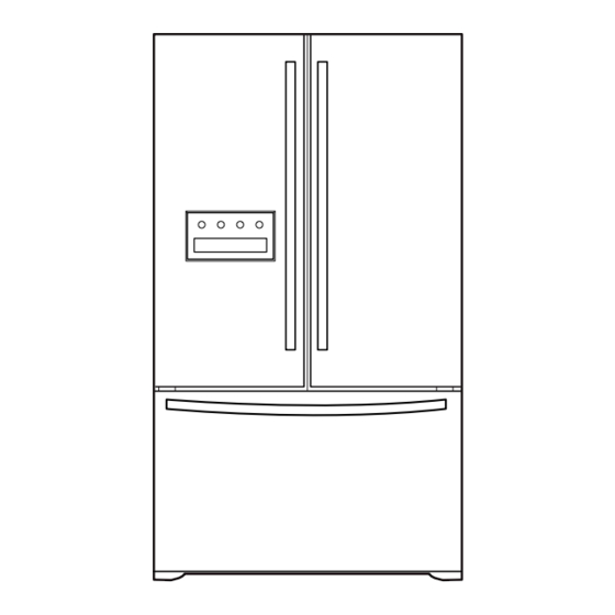
2. PARTS IDENTIFICATION Use this page to become more familiar with the parts and features. Page references are included for your convenience. NOTE: This guide covers several different models. The refrigerator you have purchased may have some or all of the items listed below. -
Page 6: Disassembly
3. DISASSEMBLY 3-1 REMOVING AND REPLACING REFRIGERATOR DOORS To remove the left refrigerator door: To remove the right refrigerator door: Before attempting to remove the left door, locate the water connection at the back of the refrigerator. Pull the water tubing that comes out of the refrigerator by pushing in on the release ring while pulling on the water line as shown in the illustration below. -
Page 7: Door
3-2 DOOR Door Gasket Replacement 1. Insert gasket bracket clips Door Gasket Removal 1) Insert gasket bracket edge beneath door frame edge. 1. Remove door frame cover 2) Turn upper gasket bracket spring so that the spring Starting at top of cover and working down, snap cover ends are in the door channel. -
Page 8: Door Alignment
2) Press gasket into channels on the three remaining 3-3 DOOR ALIGNMENT sides of door. If the space between your doors is uneven, follow the instructions below to align the doors: 1. With one hand, lift up the door you want to raise at middle hinge. -
Page 9: Ice Fan Scroll Assembly Replacement
* Ice Fan Scroll Assembly Replacement 3-6 LAMP Unplug Refrigerator, or disconnect power at the circuit 1) Remove the plastic guide for slides on left side by breaker. unscrewing phillips head screws. If necessary, remove top shelf or shelves. 2) Pull the grille forward as shown in the second picture. 3-6-1 Refrigerator Compartment Lamp 3) Disconnect wire harness of the grille 1) Release 2 screws. -
Page 10: Multi Dug, Main Pwb
3-7 MULTI DUCT 1. Remove the upper and lower Caps by using a flat screwdriver, and remove 2 screws. (Figure 17) 2. Disconnect the lead wire on the bottom position. Figure 16 3-8 MAIN PWB 1) Loosen the 4 screws on the PWB cover. 2) Remove the PWB cover 3) Disconnect wire harness and replace the main PWB in the reverse order of removal. -
Page 11: Serviceabilty Reviewfor Hidden Dispenser
3-9 SERVICEABILITY REVIEW FOR HIDDEN DISPENSER 1) With the unit unlugged from the power source, 2) Unscrew left and right side (cross driver) you can manually open the dispenser cover using a small flat blade screwdriver. The cover will remain opened during the repair. - Page 12 7) Unscrew 2 points to separate 8) Separate the Tray-cover after pull them tray-cover toward your body. 9) Pull down funnel . 10) Fix the left rib and the right rib at the marked spots correctly. 11) Before separation of Bracket, connecting rod have to be at back side position.
- Page 13 13) Unscrew 3 points at the Duct Assembly. 14) Pull down and rotate toward your body duct assembly for separation. 15) All harness have to be separated. 16) Unscrew the 1 screw at the gear ( left and right) 17) Separate gear ( left and right) 18) Unscrew 2 point with short length driver - 13 -...
- Page 14 19) Pull motor box inside and then 20) Sensor box can be disassembled separate harness. after removal of 3 screws in same case of motor box. - 14 -...
-
Page 15: Ice Corner Door Replacemen, Icemaker Assembly
3) It separates a ground connection screw. 3-10 ICE CORNER DOOR REPLACEMENT 1) Loosen the front screw as shown in the picture. 2) Lift up the hinge with one hand. 3) Pull out the Ice Corner Door with the other hand. hinge 3-11 ICEMAKER ASSEMBLY 1) Loosen two screws as shown in the first picture. -
Page 16: Auger Motor Cover, How To Remove The Pcb
3-12 AUGER MOTOR COVER 2) Unscrew one screw fixing the Cover Front and the Sub PCB. 1) After removing the icemaker remove the (5) stainless screws holding the auger motor cover, shown in the picutres below. 3) Pull the Cover Front to remove. 2) Grip the bottom of motor cover assembly and pull out it. -
Page 17: How To Remove A Door Ice Bin, How To Insert A Door Ice Bin
3-14 HOW TO REMOVE A DOOR ICE BIN 3-15 HOW TO INSERT A DOOR ICE BIN 1) Grip the handles, as shown in the picture. 1) Insert the Ice Bin, slightly tilting it to avoid touching the Icemaker. (especially, ice maker lever) 2) Lift the lower part slightly. -
Page 18: How To Remove And Reinstall The Pullout Drawer
3-16 HOW TO REMOVE AND REINSTALL THE PULLOUT DRAWER 3-16-1 Follow Steps to Remove Step 1) Open the freezer door. Step 2) Remove the lower basket. Step 3) Remove the two screws from the guide rails (one Step 4) Lift the freezer door up to unhook it from the rail from each side). - Page 19 3-16-2 Follow Steps to Reinstall Step 1) Reinstall the right side gear into the clip. Step 2) Insert the rail into the right side gear. Gears do not Step 3) Insert the rail into the left side gear, and insert the need to be perpendicular to each other.
-
Page 20: Water Valve Disassembly Method
3-17. WATER VALVE DISASSEMBLY METHOD 3-18. FAN AND FAN MOTOR DISASSEMBLY METHOD 1) Using a short screwdriver, loosen one SCREW in 1) Turn off the water. Then separate the water line from the DRAIN PIPE ASSEMBLY and one connected to the valve. -
Page 21: Pull Out Drawer
3-19 PULL OUT DRAWER o separate the drawer, push the front left and right hooks direction to pull up and remove. Then gently lift the gear part of rear left and right side of the drawer and pull it out in direction. -
Page 22: Adjustment
4. ADJUSTMENT 4-1 COMPRESSOR 4-2-3 PTC-Applied Circuit Diagram Starting Method for the Motor 4-1-1 Role The compressor intakes low temperature and low pressure gas from the evaporator of the refrigerator and compresses OVERLOAD PROTECTOR this gas to high-temperature and high-pressure gas. It then delivers the gas to the condenser. -
Page 23: Olp(Overload Protector)
4-3 OLP (OVERLOAD PROTECTOR) 4-4 TO REMOVE THE COVER PTC 4-5-1 Definition of OLP (1) OLP (OVERLOAD PROTECTOR) is attached to the Compressor and protects the Motor by opening the circuit to the Motor if the temperature rises and activating the bimetal spring in the OLP. (2) When high current flows to the Compressor motor, the Bimetal works by heating the heater inside the OLP, and the OLP protects the Motor by cutting off the... -
Page 24: Circuit Diagram
5. CIRCUIT DIAGRAM - 24 -... -
Page 25: Troubleshooting
6. TROUBLESHOOTING 6-1 COMPRESSOR AND ELECTRIC COMPONENTS (Rated Voltage Remove PTC-Starter Power Source. ±10%)? from Compressor and measure voltage between Terminal C of Compressor and Terminal 5 or 6 of PTC. OLP disconnected? No Voltage. Replace OLP. Check connection condition. Reconnect. - Page 26 6-2 OTHER ELECTRICAL COMPONENTS Not cooling at all Check for open short or Compressor Cause incorrect resistance readings doesn't run. in the following components a. Starting devices Short, open, or broken. Poor contact b. OLP or shorted. Coil open or shorted. c.
-
Page 27: Service Diagnosis Chart
6-3 SERVICE DIAGNOSIS CHART COMPLAINT POINTS TO BE CHECKED REMEDY No Cooling. • Is the power cord unplugged from the outlet? • Plug into the outlet. • Check if the power switch is set to OFF. • Set the switch to ON. •... - Page 28 6-4 REFRIGERATION CYCLE Troubleshooting Chart TEMPERATURE STATE OF STATE OF THE CAUSE REMARKS OF THE THE UNIT EVAPORATOR COMPRESSOR PARTIAL Freezer Low flowing sound of A little higher • Refrigerant level is low due LEAKAGE compartment and Refrigerant is heard and than ambient •...
- Page 29 6-4-1 SEALED SYSTEM DIAGNOSIS “Not Cooling” Complaint All components operating, No airflow problems, Not frosted up as a defrost problem problem has been isolated to sealed system area Frost None Partial Pattern? Equalization Equalization Test Test Very Fast Very Slow Very Slow Fast Very Fast...
- Page 30 6-5 OPERATION PRINCIPLE 6-5-1 Operation Principle of IceMaker Power On Start Position • Adjusts EJECTOR to Start Position with power on. Icemaking • Waits until water becomes ICE after starting the Mode icemaking operation. Harvest • Runs MOTOR to drop ice from the tray into the ICE BIN. Mode (During harvest mode, check if the ice bin is full) Park Position...
- Page 31 6-6 ICE MAKER FUNCTIONS 6-6-1. Icemaking Mode 1. Icemaking refers to the freezing of supplied water in the ice tray. Complete freezing is assured by measuring the temperature of the Tray with Icemaking SENSOR. 2. Icemaking starts after completion of the water fill operation. 3.
- Page 32 6-6-4 Function TEST 1. This is a forced operation for TEST, Service, cleaning, etc. It is operated by pressing and holding the Fill Key for 3 seconds. 2. The test works only in the Icemaking Mode. It cannot be entered from the Harvest or Fill mode. 3.
- Page 33 6-8 Hidden Dispenser 6-8-1 Hidden Dispenser Logic Scene Process Lock Display Button Water Open/Close Push the Display Button Begin to Use (Open/Close or Water the Dispenser or Ice Button) Button Tray Motor On Disturb the Tilt-Out (Tilt-Out Direction) When the user cancels the Sensing the Reverse Rotation Lock and closes the...
- Page 34 6-9 Hidden Dispenser operation 6-9-1 Open/Close 1. When the power is connected to the refrigerator for the first time, the Dispenser will close once. 2. When you press the Open/Close, Water and Ice Button while the Dispenser is closed, the Dispenser will be opened. 3.
- Page 35 6-10. Error Code Summary w w WARNING : When you check the Resistance values, be sure to turn off the power. And wait for the voltage-discharge sufficiently. Error Display Error Detection Error Generation Factors Remark Freezer Ref. Category Temperature Temperature Normality None Normal operation of Display...
- Page 36 6-11. Troubleshooting With Error Freezer Sensor Error F-Sensor CON6 Main PWB Wiring diagram Disconnect CON6 and measure Replace Is Er-FS displayed? the value. Is resistance value -sensor between pins 11 & 12 of CON6 (Position as below? (BL to BL) No : 610C) pin12 pin11...
- Page 37 Refrigerator Sensor Error R-Sensor CON6 Main PWB Wiring diagram Disconnect CON6 and measure Replace Is Er-FS displayed? the value. Is resistance value R-sensor between pins 9 & 10 of CON6 as (Position below? (WH to WH) No : 610B) pin9 pin10 Is the connection loose? Reconnect...
- Page 38 Defrost Sensor Error D-Sensor CON6 Main PWB Housing-A Wiring diagram Replace Is Er-dS displayed? Is resistance value between D-sensor pins 1 & 2 of Housing- A as (Position below? (BO to BO) No : 400A pin2 pin1 Is the connection loose? Reconnect Checking Open or Short of wire Test Point...
- Page 39 Icing Room Sensor Error Icing-Sensor CON9 Main Housing-A Wiring diagram Replace Is resistance value between Is Er-IS displayed? Icing-sensor pins 1 & 2 of Housing- A as (Position below? (BL to BL) No : 600B Is the connection loose? Reconnect pin1 BL pin2 BL Inner of Icing door...
- Page 40 Defrost Heater Error D-Sensor FUSE-M Main DEF-Heater Housing-A CON6 CON3 Wiring diagram Enter the TEST 3 MODE Replace Is Er-dH displayed? Is the voltage value MAIN PWB between pins 10(WH) and (Position No: 4 (BL) of CON3 115 V AC? 500A) Is the connection loose? Reconnect...
- Page 41 Replace Is the resistance value of Is the resistance value Heater Normal heater like as below? between pins 10(WH) (Position No: 408A) And 4(BL) of CON3 like as below? pin10 WH pin4 BL CON3 Resistance Resistance Resistance Resistance Test Point Result Heater Resist ance Heater Resist ance...
- Page 42 Freezer Fan Error Main F-FAN CON4 Housing Wiring diagram Check fan motor Is Er-FF displayed? Does the old-air come out (Connector, of the top of the main duct Frozen, Locked) under Test1 mode ? and Replace (Position No : 404A) Is the connection loose? Reconnect Is the feedback voltage...
- Page 43 Condenser Fan Error CON4 C-FAN Main PWB Housing Wiring diagram Is Er-CF displayed? Is the condenser fan Check fan motor (Connector, rotate under Test1 mode? Locked,mouse) and replace. (Position No: 420A) Is the connection loose? Reconnect Is the feedback voltage Replace between pin9 and pin10 of MAIN PWB...
- Page 44 Icing Room Fan Error Icing Main PWB Housing CON4 Wiring diagram Is Er-IF displayed? Does the cold- air come out Check fan motor (Connector, of the side duct under the Frozen,Locked) Test1 Mode? and replace. (Position No : 407A) Is the connection loose? Reconnect Is the feedback voltage Replace...
- Page 45 Communication Error Hinge CON5 CON01 RD(Tx) RDRx) BN(Rx) BN(Tx) MAIN DISPLAY BO(GND) BO(GND) WH/BK(12V) WH/BK(12V) * Rx: Receiver Wiring diagram Tx: Transmitter Top Display PWB Replace the Is Er-CO displayed? Top Display Is the voltage between pin2 and pin4 of CON01 (Position 0 V or 5 V? No : 207C)
- Page 46 MAIN PWB Main PWB Replace Reconnect MAIN PWB Is the connection loose? Is the voltage between (Position No: pin2 and pin4 of CON5 500A) 0 V or 5 V? pin2 BO pin4 RD Main PWB Transmitter Voltages Replace Is the voltage between MAIN PWB pin 2 and pin 3 of (Position No:...
- Page 47 6-12. Troubleshooting Else ICE Mode doesnÕt work Housing-A CON2 CUBE Solenoid Dispenser Auger Motor Housing-B Solenoid Dispenser Wiring diagram In ICE Mode, Replace Dispenser PWB Reconnect Is the voltage between pin2 Dispenser Is the connection loose? and pin12 of CON2 like as below, while pushing the (Position No: ICE lever switch?
- Page 48 In ICE Mode, Replace Replace Is the resistance value Auger Motor Is the voltage between pin2 Dispenser between (1) and (2) of the (Position No: and pin6 of CON2 like as Auger motor like as below? 606A) below, while pushing the (Position No: ICE lever switch? 155A)
- Page 49 Replace Is the resistance between Dispenser (1) and (2) of the Dispenser Solenoid solenoid like as below? (Position No: 405A) (1) (2) Resistance of Dispenser solenoid Test Point Result (1) To (2) 44 ~ 54 ½ Replace Is the condition of Micro the micro switch like as Switch...
- Page 50 Water Mode DoesnÕt work Dispenser Door Water Valve Housing-A CON2 Main Machine Room Water Valve Housing-B CON3 Wiring diagram Replace In Water Mode, Dispenser PWB Dispenser Is the voltage between Reconnect Is the connection loose? pin1 and pin11 of CON2 in (Position No: dispenser PWB like as 155A)
-
Page 51: Door Ice Maker
Replace In Water Mode, Second Water- valve Replace Second Is the voltage between Is the resistance value of MAIN PWB Water-valve pin4 and pin11 of CON3 in Second-water valve like as (Position No: (Position No: main PWB like as below, below? 500A) 619B) - Page 52 Freezer-LED Module DoesnÕt work Main PWB F-LED F-DOOR Switch MODULE CON6 Replace Replace Door switch Is the voltage between pin 14 Is the condition of MAIN PWB and pin15 of CON6 like as (Position No: the freezer door switch (Position No: below? 406B) like as below?
- Page 53 1.Check the harness 1.Check the harness Is the voltage between Is the voltage between open or short open or short pin2 and pin3 of pin 1 and pin2 of 2.Replace F LED Freezer LED Module Freezer LED Module Module (Position No Housing? Housing? : 409E)
- Page 54 Refrigerator-LED Module DoesnÕt work Main PWB CON6 R-DOOR Switch BL/WH CON5 R-LED MODULE BL/WH CON4 Replace Is the connection loose? Is the condition of Reconnect Door switch the freezer door switch (Position No: like as below? 402A) CON6 Replace Status Tester Is the voltage between pin 14 MAIN PWB...
- Page 55 Is the voltage between 1.Check the harness Is the voltage between pin 13 Replace pin 1 and pin2 of open or short and 15 of CON6 like as MAIN PWB Refrigerator LED Module 2.Replace R LED below? (Position No: Housing? Module (Position No 500A) : 409D)
- Page 56 Check the harness Is the voltage between Reconnect Ye s Is the connection loose? open or short pin2 and pin3 of Refrigerator LED Module Housing? CON4 Is the voltage between pin 1 Replace and 14 of CON4 like as below? MAIN PWB (Position No: 500A)
- Page 57 Poor cooling in the refrigerator compartment Replace MAIN PWB Is the voltage between Reconnect Is the connection loose? MAIN PWB of CON4 pins 2 and pin 3 (Position No: like as below? 500A) pin2 WH Pin3 BK CON3 CON4 Voltage of F-fan Replace Enter the TEST 1 MODE Test Point...
- Page 58 Does the old-air come out , take steps to PWB as Check the After reset the unit of the top of the main duct? follows for temperature compensation. Damper itself 1. In the case of EBR419564 : Compensate with Jump wire cutting JUMP Temp.
- Page 59 Over cooling in the refrigerator compartment MAIN PWB Enter the TEST 2 MODE Check the Reconnect Is the connection loose? Does the cold-air coming Damper itself out of the top of the main duct.? CON3 Replace Enter the TEST 1 MODE MAIN PWB Is the voltage between Replace...
- Page 60 After reset the unit , take steps to PWB as Enter the TEST 3 MODE Replace follows for temperature compensation. MAIN PWB Is the voltage between (Position No: Pins 4 and pin 12 500A) CON3 like as below? 1. In the case of EBR419564 : Compensate with Jump wire cutting CON3 Pin12 BK...
- Page 61 [NOTE] 2. How To Start Test Mode 1. How To Remove Terminal Position Push the TEST button on the Main PWB, Assurance (TPA) You can start the TEST MODE. * AC TPA TEST BUTTON * DC TPA After measure the values, ∆...
- Page 62 6-13. How to check the Fan-Error (1) EBR419564 After sending a signal to the fan, the MICOM checks the BLDC fan motor s lock status. If there is no feedback signal from the BLDC fan, the fan motor stops for 10 seconds and then is powered again for 15 seconds.
-
Page 63: Component Testing Information
7. COMPONENT TESTING INFORMATION 7-1. Defrost Controller Assembly Function - Controller assembly is consist of 2 kinds of part those are fuse-m and sensor. we can decide part is defect or not when we check the resistance. - Fuse-m can cut off the source when defrost heater operate the unusual high temperature. - Page 64 7-2. Sheath Heater Function Sheath heater is a part for defrost. All heating wire is connected to only one line. So we can decide part is defect or not when we check the resistance. How to Measure Set a ohmmeter connect to The 2 housing pin. Measure the 2 pin connected to Sheath Heater.
- Page 65 7-3. Door Heater Assembly Function The heater is designed to prevent the raising dew from door. How to Measure Standard Test Point Ressult (1) to (2) 2.3 ~2.9 k‰ - 65 -...
-
Page 66: Door Switch
7-4. Door Switch Function The switch sense if the door open or close. - When the door open, lamp on. - When the door open, the switch give information to Micom. When the door open, internal contact operate on and off moving plunger of door switch up and down. - Page 67 7-5. Solenoid Function - Dispenser solenoid : When customer push the dispenser button, Pull duct door and abstract from ice bank. How to Measure Dispenser Solenoid Standard Dispenser Solenoid Test Points Result (1) to (2) 44 ~ 54 ‰ - 67 -...
- Page 68 7-6. AC Motor ASSEMBLY (Geared Motor & Solenoid) Function The Geared Motor of ac motor assembly advances forward the ice by rotating the ice and The solenoid of ac motor assembly selects one of the cube mode or crush mode. - Cube solenoid : Pulling the stir lip for moving the ice in ice maker system.
- Page 69 7-7. Damper Function The damper supplies the cold air at freezer room to chillroom by using the damper s plate. Chillroom is colder than before when damper s plate is open. When damper s plate is close, chillroom s temperature will rise. How to Measure <...
-
Page 70: Water Valve
7-8. Water Valve Function - first-Water Valve (in machine room) : supply the water from city water to water filter in refrigerator - second-Water Valve (in door) : supply the water from water filter to icemaker and dispenser How to Measure Dispense Ice Maker... - Page 71 7-9. Main PWB Assembly (EBR41956404) CON5 CON4 CON9 CON6 CON2 CON1 CON3 - 71 -...
- Page 72 7-10. Display and Dispenser Drive PWB Assembly CON01 Top Display PWB CON101 CON106 CON102 CON103 CON104 CON105 Dispenser Display PWB CON1 CON2 Dispenser PWB - 72 -...
- Page 73 795.78733.804 F or S ears profes s ional ins tallation of home appliances and items like garage door openers and water heaters .
- Page 74 C A S E P A R T S C A UT ION: Us e the part number to order part, not the pos ition number. 607A 603C 603B S 03 S 01 626A 624D 207B 402A 103B 624C S 01 S 03 103A 624A...
- Page 75 CASE PARTS Loc No. 787*3(ST) 787*9( 103A 3650JA2061X 3650JA2113N Handle, Rear 103B 3650JA2061W 3650JA2113P Handle, Rear 103C ACQ55957504 ACQ55957503 Cover Assembly, Lower 105A 5251JA3003D 5251JA3003D Tube Assembly, Drain 106A 4779JJ2001B 4779JJ2001B Leg Assembly, Adjust 120A ADJ36702004 ADJ36702004 Duct Assembly, Multi 120B MCZ47932702 MCZ47932702...
- Page 76 C A S E P A R T S L OC No. 787*3(S T ) 787*9(WB ) Des c 400A 6615J B 2005H 6615J B 2005H C ontroller As s embly 402A 6600J B 3007K 6600J B 3007J S witch, P us h B utton 404A 4681J B1027C 4681JB1027C...
- Page 77 FREEZER PARTS CAUTION: Use the part number to order part, not the position number. 250C 250D 145C 250E 250D 250C 136B 145G 145J 131A 145K 145F 145M 145J 145H 237C 136A LOC No. 787*3(ST) 787*9(WB) Description 131A 5074JA2004A 5074JA2004A Bucket, Ice 136A 3391JJ2011M 3391JJ2011M...
-
Page 78: Refrigerator Parts
REFRIGERATOR PARTS CAUTION: Use the part number to order part, not the position number. 141B 141A 141A 141B 141C 141B 141A 141C 140A 141C 142D 161C 141D 161B 142B 142A 154A 151B 151A 146E 162B 161A 145E 145D 162A Loc No. 787*3(ST) 787*9(WB) Desc... -
Page 79: Door Parts
DOOR PARTS CAUTION: Use the part number to order part, not the position number. 241C 241B 230B 230A 241A 231B 233B 233C 233D 233A 231A 234D 234C 212G 234A 234B 241D 241D 155A 243C 243C 262C 241F 262C 243A 243A 243B 244A 615A... - Page 80 DOOR PARTS LOCNo. 787*3(ST) 787*9(WB) Desc 147A 5074JJ1016A 5074JJ1016A Bucket, Dairy 147C 3550JJ1084A 3550JJ1084A Cover, Bucket 155A ACQ67639201 ACQ67639201 Cover Assembly, PCB 200A ADC57728001 ADC57728003 Door Assembly, Freezer 201A ADD57728201 ADD57728203 Door Foam Assembly, Freezer 203A MDS38201406 MDS38201402 Gasket, Door 205A 5004JJ1061B 5004JJ1061B...
- Page 81 DISPENSER PARTS 275C 275B 405A 276B 275A 303F 407C 303E 276A 407D 280F 402C 238D 280E 280D 333A 616K 412D 412C 412A 412B 500B 280C 279C LOCNo. 787*3(ST) 787*9(WB) Desc 238D MDR47984501 MDR47984501 Funnel 262B MCD56869401 MCD56869401 Connector, Tube 275A 5007JA3006X 5007JA3006X Cap Assembly, Duct...
- Page 82 ICE MAKER & ICE BANK PARTS 612A 600B 630J 600A 611A 630F 630B 630C 630A 630K 630M 630H 606A 614A 630E 630N 630D 630G 630L LOCNo. 787*3(ST) 787*9(WB) Desc 600A AEQ36756901 AEQ36756901 Ice Maker Assembly, Kit 600B 6500JB1008A 6500JB1008A Sensor, Temperature 612A 4681JA1006D 4681JA1006D...