Table of Contents
Advertisement
Quick Links
Download this manual
See also:
User Manual
Advertisement
Table of Contents

Related Manuals for Acer E101


Summary of Contents for Acer E101
-
Page 1: Service Guide
E101 Smartphone Service Guide Service guide files and updates are available on the ACER/CSD web; for more information, please refer to http://csd.acer.com.tw PRINTED IN TAIWAN... -
Page 2: Revision History
Revision History Please refer to the table below for the updates made on the F900 smartphone service guide. Date Chapter Updates... - Page 3 Copyright Copyright © 2009 by Acer Incorporated. All rights reserved. No part of this publication may be reproduced, transmitted, transcribed, stored in a retrieval system, or translated into any language or computer language, in any form or by any means, electronic, mechanical, magnetic, optical, chemical, manual or otherwise, without the prior written permission of Acer Incorporated.
- Page 4 Conventions The following conventions are used in this manual: Denotes actual messages that SCREEN MESSAGES appear on screen. NOTE Gives bits and pieces of additional information related to the current topic. WARNING Alerts you to any damage that might result from doing or not doing specific actions.
- Page 5 DIFFERENT part number code to those given in the FRU list of this printed Service Guide. You MUST use the list provided by your regional Acer office to order FRU parts for repair and service of customer machines.
-
Page 7: Table Of Contents
Your Acer Smartphone Tour ........ - Page 8 E101 Smartphone Exploded Diagram ........80...
-
Page 9: System Specifications
Chapter 1 System Specifications Features Below is a brief summary of the smartphone’s many features: Operating System • Windows Mobile® 6.1 Professional for Pocket PC Phone Edition Processor • 1.Qualcomm MSM7225 Mobile Station Modem Memory • 512MB Bootable NAND FLASH, 256MB SDRAM Display •... - Page 10 MSN® Messenger / Microsoft® Transcriber / Windows Media® Player 10 • Picture / Notes / Internet Explorer Mobile / ActiveSync / Calculator / Game (Solitaire, Bubble Breaker) • Microsoft Reader* (* depends on region) Acer Exclusive Applications • User interface: • Acer Shell v2.0 •...
-
Page 11: System Block Diagram
• Phone Application*, Phone Setting, SIM Toolkit, Speed Dial, Call Filter, Wireless Modem, Wireless Manager, Dialer Skin, Add Ringtone, CSD Type, Voice Commander*, Connection Wizard, SMS Sender, MMS Composer*, SIM Manager, Video Telephony, (*Subject to change by region) • Multimedia Tools: •... -
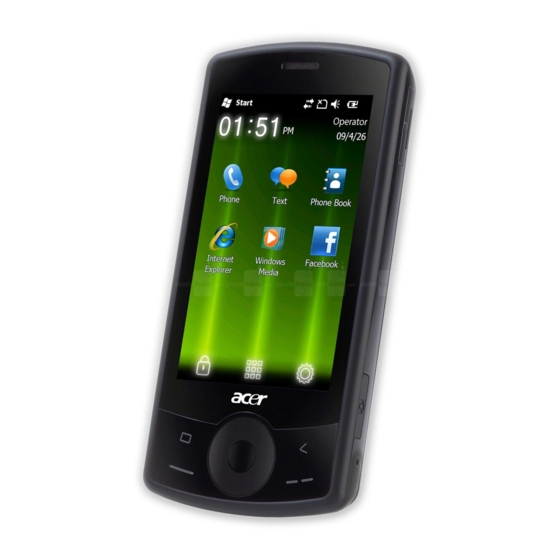
Page 12: Your Acer Smartphone Tour
Your Acer Smartphone Tour After examining your smartphone features, let us show you around your new smartphone. Views Item Description Stylus Use to enter information or select items on the touch screen. Power button Press to turn the screen on/off or enter sleep mode; press and hold to turn the smartphone off. -
Page 13: Hardware Specifications And Configurations
Item Description Micro SD card slot Expand your device’s memory capacity. Camera button Activate the camera or take a picture. Reset pinhole Insert the stylus into this hole to reset the device. Speaker Emits audio from your smartphone; suitable for handsfree use. Camera A 2-megapixel camera for taking high-resolution images. - Page 14 Item Specification Pixel Pitch (mm) 174 × 174 Typical White Luminance (cd/m also called Brightness Supported Colors 262000 Contrast Ratio 500:1 Response Time (Optical Rise Time/Fall Time) msec Weight 18 g Physical Size (mm) 47.4(W) x 81.2(H) x 2 (D) Electrical Interface RGB666 Viewing Angle (degree)
-
Page 15: Software Upgrades
Chapter 2 Software Upgrades System Requirements • Microsoft® Windows XP or above • Latest version of EUU (End-user Upgrade Utility / EUU_xxx.exe) • Latest version of ActiveSync v4.5 or above • Tool: USB Cable Mode Switching Performing a Soft Reset Press and hold the POWER button. - Page 16 Execute the EUU executable file The Welcome screen displays. Click Next. Specify a folder and permission.
- Page 17 Click Next. The Confirm Installation screen displays. Click Next. When EUU is installed, the Completed screen displays.
- Page 18 Click Finish. The Device Software Update Utility starts and the following screen displays. Follow the on screen instructions. When the ActiveSync connection is established, click Next. The following screen displays.
- Page 19 10. Click Continue. A warning screen displays. 11. Click Yes. A confirmation screen appears on the Smartphone. 12. Click Yes. A final confirmation screen appears on the PC.
- Page 20 13. Click Yes to begin the upgrade. The Smartphone reboots to download mode and the following progress screens display on the Smartphone and PC. The update is complete when the following screen displays. 14. Click Close to exit the utility.
-
Page 21: Machine Disassembly And Replacement
Chapter 3 Machine Disassembly and Replacement This chapter contains step-by-step procedures on how to disassemble and reassemble the smartphone for maintenance and troubleshooting. IMPORTANT:The use of metal tools during disassembly may damage the casing. Use plastic tools where possible. IMPORTANT:Cover the work area with a clean, dry, lint-free cloth before placing the smartphone face down. NOTE: The color and layout of some components may differ from those shown in the images. -
Page 22: External Module Disassembly Process
Main Screw List Screw Quantity Part No. M 1.6X4.0,M WT NYLOK C 6052A0067302 I M 1.2X1.5 WT Ni GP, 6052A0067402 5T, M1.6X3.0 M BK Ni VER:02,GP 6052A0067502 External Module Disassembly Process External Modules Disassembly Flowchart Turn off system power Disconnect USB cable from system Remove Remove... -
Page 23: Removing The Stylus
Removing the Stylus Grasp the Stylus as shown and pull to remove it from the smartphone. Continue to pull the Stylus until it is completely removed from the smartphone. Chapter 3... -
Page 24: Removing The Mini-Sd Card
Removing the Mini-SD Card NOTE: The Mini SD Card is an optional item and may not be present. Insert a finger nail (or plastic pry) into the casing and open the Mini SD door as shown. Pull the hinge out (1) and rotate the Mini SD door away from the card slot (2) as shown. Press the Mini SD card into the slot and release. - Page 25 Remove the card from the slot and replace the Mini SD door. Chapter 3...
-
Page 26: Removing The Battery Door
Removing the Battery Door IMPORTANT:Cover the work area with a clean, dry, lint-free cloth before placing the smartphone face down. Slide the Battery Door downwards until it disengages. Rotate the Battery Door away from the smartphone to remove it. Chapter 3... -
Page 27: Removing The Battery
Removing the Battery See “Removing the Battery Door” on page 18. Push the Battery towards the top of the Smartphone as shown to release it. Lift the Battery out of the battery bay. Chapter 3... -
Page 28: Removing The Sim Card
Removing the SIM Card NOTE: The SIM Card is an optional item and may not be present. See “Removing the Battery” on page 19. Grasp the SIM Card as shown. Slide the SIM Card out of the slot as shown. Chapter 3... -
Page 29: Main Unit Disassembly Process
Main Unit Disassembly Process Main Unit Disassembly Flowchart Remove External Remove Remove Remove Remove Modules before Back Cover Camera Shielding Mainboard Receiver Module proceeding Remove Remove Remove Remove Vibration Module Camera Module LCD Panel LED Gasket Remove Remove Remove Sim Daughter Speaker Module Button Board Board... -
Page 30: Removing The Back Case
Removing the Back Case See “Removing the Battery” on page 19. Remove the five screws located in the back case. NOTE: The lower right screw is covered with a factory seal. Note if this seal is already broken. Step Screw Quantity Screw Type Back Case... - Page 31 Use the same technique to release the securing clip on the top edge of the Smartphone (clip circled below). Separate the bottom edge of the Smartphone using a pry tool as shown. The securing clip is located in the center of the bottom edge. Separate the edges using a pry tool down the left side, gradually prying apart the covers.
- Page 32 Work along the left edge, prying the covers apart as shown. Remove the Top Case from the Back Case and place it on a clean, dry, lint-free cloth. NOTE: Take care when separating the covers. The Silent Button is not attached to either cover and can easily fall out.
- Page 33 10. Note the condition of the water detection sticker, shown below: The water detection sticker dissolves when in contact with water for an extended period. Chapter 3...
-
Page 34: Removing The Vibration Module
Removing the Vibration Module See “Removing the Back Case” on page 22. Using the tweezers, gently pry the Vibration Module loose of the Back Case. Grasp the rubber insulation and lift the Vibration Module out of the Back Case. Chapter 3... -
Page 35: Removing The Speaker
Removing the Speaker See “Removing the Back Case” on page 22. Using the tweezers, gently pry the Speaker loose of the Back Case. The speaker is glued in place so care must be taken to remove not only the speaker but the glue below it as well Lift the speaker away from the Back Case. -
Page 36: Removing The Side Buttons
Removing the Side Buttons See “Removing the Back Case” on page 22. Grasp the Volume Button and lift it out of the Back Case. Grasp the Camera Button and lift it out of the Back Case. Push the Power Button in to release it from the securing tabs. Chapter 3... - Page 37 Grasp the Power Button and lift it out of the Back Case. Grasp the Silent Button and lift it out of the Back Case. Grasp the outer ring of the Reset Button and slide it up along the pin. Chapter 3...
- Page 38 Lift the Reset Button out of the Back Case. Chapter 3...
-
Page 39: Removing The Microphone Boot
Removing the Microphone Boot See “Removing the Back Case” on page 22. Grasp the Microphone Boot and lift it out of the Back Case. Chapter 3... -
Page 40: Removing The Sim Daughter Board
Removing the SIM Daughter Board See “Removing the Vibration Module” on page 26. Remove the two screws securing the SIM Daughter Board to the Mainboard. Step Screw Quantity Screw Type SIM Board M1.6*3 Lift the SIM Daughter Board away from the Mainboard as shown. Chapter 3... -
Page 41: Removing The Camera Shielding
Removing the Camera Shielding See “Removing the SIM Daughter Board” on page 32. Insert thin tine tweezers under all four sides of the Shielding securing clips and gently pry the Shielding away from the Mainboard. Lift the Shielding clear of the Mainboard to expose the Camera Module. Chapter 3... -
Page 42: Removing The Camera Module
Removing the Camera Module See “Removing the Camera Shielding” on page 33. IMPORTANT:use the camera removal tool, shown below, to replace the camera. Insert the camera removal tool into the camera well on the mainboard as shown until the clips on the outside edges disengage. -
Page 43: Removing The Mainboard
Removing the Mainboard See “Removing the Back Case” on page 22. Pry the securing hook off of the right side of the mainboard while gently pulling up the Mainboard. Pull up on the bottom right side of the mainboard to detach the connector to the Keyboard. Pull up on the edge of the mainboard to release it from the pin circled below Slide the mainboard out from under the securing clip shown below. - Page 44 IMPORTANT:The LCD Module is not secured to the Top Case or Mainboard. Support the panel before turning the assembly over. Holding the Top Case and Mainboard together, flip the assembly over. Lift the Top Case away from the Mainboard. IMPORTANT:Ensure that no dust, dirt, or finger prints come in to contact with the exposed LCD Module or Top Case;...
-
Page 45: Removing The Lcd Module
Removing the LCD Module IMPORTANT:Ensure that no dust, dirt, or finger prints come in to contact with the exposed LCD Module or Top Case; Foreign particles and grease will affect LCD output performance. If any prints or dust comes into contact with the LCD, use only water, IPA (Isopropyl Alcohol) or Hexane and approved cleaning cloth. -
Page 46: Removing The Light Pipe Foam
Removing the Light Pipe Foam A small rubber gasket directs light from the power indicator LED to the top case. See “Removing the Mainboard” on page 35. Grasp the Light Pipe Foam and lift it out of the Top Case. Chapter 3... -
Page 47: Removing The Receiver Module
Removing the Receiver Module See “Removing the Vibration Module” on page 26. Pull the grounding tab up as shown. Pull the receiver module out to disengage the adhesive and lift it clear of the Top Case. Chapter 3... -
Page 48: Removing The Keyboard
Removing the Keyboard See “Removing the Mainboard” on page 35. Remove the tape securing the Touchscreen FFC to the connector. Remove the tape securing the Touchwheel FFC to the connector. Lift the FFC locking latch and disconnect the Touchscreen FFC as shown. Chapter 3... - Page 49 Lift the FFC locking latch and disconnect the Touchwheel FFC as shown. Lift the Touchwheel Board away from the Button Board and remove the six screws securing the Keyboard to the Top Case. Step Screw Quantity Screw Type Button Board M1.2*1.6 Slide the Keyboard (K/B) out from the slot in the Top Case.
-
Page 50: Removing The Touchwheel
Removing the Touchwheel See “Removing the Keyboard” on page 40. Push the two pins down into the holes as indicated Slide the Touchwheel out from the Top Case IMPORTANT:Take care when removing to not allow the Touchwheel Board to get snagged and torn. Chapter 3... -
Page 51: Replacing Internal Module Components
Replacing Internal Module Components Replacing the Touchwheel Slide the Touchwheel into the opening in the Top Case, making sure the Touchwheel Board clears the opening. Push the Touchwheel onto the pins as shown. Chapter 3... -
Page 52: Replacing The Keyboard
Replacing the Keyboard Slide the Keyboard into the slot in the Top Case and under the Touchwheel Board as shown. Insert the six screws to secure the Button Board to the Top Case Step Screw Quantity Screw Type Button Board M1.2*1.6 Insert the Touchwheel FFC into the connector and close the FFC locking latch as shown. - Page 53 IMPORTANT:After closing, only one of the two white lines on the FFC should be visible, and should be flush with the edge of the locking mechanism. Insert the Touchscreen FFC into the connector and close the FFC locking latch as shown IMPORTANT:After closing, only one of the two white lines on the FFC should be visible, and should be flush with the edge of the locking mechanism.
-
Page 54: Replacing The Receiver Module
Replacing the Receiver Module Remove backing tape from the adhesive on the new receiver module. Insert the receiver module into the receiver well in the Top Case. Bend the grounding tab over the edge of the well and pinch closed as shown. Chapter 3... -
Page 55: Replacing The Light Pipe Foam
Replacing the Light Pipe Foam A small rubber gasket directs light from the power indicator LED to the Top Case. Grasp the Light Pipe Foam and insert it into the well in the Top Case. Replacing the LCD Module IMPORTANT:Ensure that no dust, dirt, or finger prints come in to contact with the exposed LCD Module or Top Case;... - Page 56 Connect the LCD FFC and close the FFC locking latch as shown. IMPORTANT:After closing, the white line on the FFC should be visible and flush with the edge of the locking mechanism. Adhere the tape to secure the LCD FFC to the connector. Chapter 3...
-
Page 57: Replacing The Mainboard
Replacing the Mainboard Place the Top Case onto the Mainboard. IMPORTANT:Ensure that no dust, dirt, or finger prints come in to contact with the exposed LCD Module or Top Case; Foreign particles and grease will affect LCD output performance. If any prints or dust comes into contact with the LCD or cover, use only water, IPA (Isopropyl Alcohol) or Hexane and approved cleaning cloth. - Page 58 Slide the mainboard under the hook in the Top Case circled below Press down on the base and right side to engage the hooks. NOTE: Check the four pins and screw holes to ensure the mainboard is seated properly in the Top Case. Chapter 3...
-
Page 59: Replacing The Camera Module
Replacing the Camera Module IMPORTANT:use the camera removal tool, shown below, to replace the camera. Grasp the camera using the camera removal tool - note the position of the alignment pin - it should align with the right side of the mainboard during insertion. Insert the Camera Module into the camera well on the mainboard as shown Chapter 3... -
Page 60: Replacing The Camera Shielding
Replacing the Camera Shielding Slide the Camera Shielding over the camera. Push the edges of the Camera Shielding down to be sure that the securing clips on the shielding are engaged. Replacing the SIM Daughter Board Place the SIM Daughter Board (D/B) onto the Mainboard as shown, taking care to align the screw holes. Chapter 3... -
Page 61: Replacing The Microphone Boot
Press lightly on the lower right corner of the SIM Daughter Board to engage the board-to-board connector. Insert the two screws to secure the SIM Board to the Mainboard. Step Screw Quantity Screw Type SIM Board M1.6*3 Replacing the Microphone Boot Insert the Microphone Boot into the well in the Back Case as shown. -
Page 62: Replacing The Side Buttons
Replacing the Side Buttons Insert the Volume Button into the Back Case. Insert the Camera Button into the Back Case. Insert the Power Button into the Back Case. Chapter 3... - Page 63 Push the back of the Power Button in until the face is flush with the cover to engage the securing tab. Insert the Silent Button into the well as shown. Slide the Reset Button down along the pin until it rests at the base. Chapter 3...
-
Page 64: Replacing The Speaker
Replacing the Speaker Remove any adhesive backing from the Speaker. Insert the Speaker into the Back Case. Press the speaker module in place to engage the adhesive. Replacing the Vibration Module Grasping the Vibration Module firmly from both sides, insert the Vibration Module into the vibration module well in the Back Case. -
Page 65: Replacing The Back Case
Press the vibration module into place until the edges are flush with the well. Replacing the Back Case Align the silent button switch on the Mainboard with the Silent Button in the Back Case. Close the covers, and press the right side together until the hooks snap into place, taking care to keep the silent button aligned. - Page 66 Press the bottom and top of the covers together until the hooks snap into place. Slide the silent button up and down to make sure the button is aligned with the switch on the mainboard. Pinch the edges together above and below the silent button. Chapter 3...
- Page 67 Press the silent button inwards while pressing the covers together until the back edge of the silent button snaps into place under the Back Case and the seam is flush. Replace the five screws located in the Back Case. Step Screw Quantity Screw Type...
-
Page 68: Replacing External Module Components
Replacing External Module Components Replacing the SIM Card Slide the SIM Card into the SIM slot as shown. Replacing the Battery Insert the Battery into the battery bay. Chapter 3... -
Page 69: Replacing The Battery Door
Replacing the Battery Door Place the Battery Door into the smartphone. Push the Battery Door into place. Replacing the Mini-SD Card Insert the card into the slot until it clicks into place. Chapter 3... -
Page 70: Replacing The Stylus
Rotate the Mini SD door towards the card slot as shown. Push the door into the case to secure it in place. Replacing the Stylus Push the stylus into the stylus holder in the top of the smartphone as shown. Chapter 3... -
Page 71: Diagnostics And Troubleshooting
Chapter 4 Diagnostics and Troubleshooting Using the Diagnostic Utility Installing the Diagnostic Utility. Load the file “20090918DiagForC1 Ver 1.00.24.cab” onto a micro-SD card. Insert the micro-SD card into the Smartphone. On the smartphone, click Start > File Explorer. Select Storage Card from the Show menu. Double-click the file “20090918DiagForC1 Ver 1.00.24.cab”... -
Page 72: Running The Diagnostic Program
Running the Diagnostic Program All of the diagnostic programs are accessed from the same menu. Open the file explorer. Browse to the diag folder. Double-click the DiagMain application. Select the diagnostic utility to run. See the following sections for detailed instructions. BT Phone Test Before performing this test verify the following: •... - Page 73 • Ensure that a SIM card is inserted in the phone Open the diagnostic utility. Select BT_Phone test. Click RUN. Click 2. The phone function activates. Make a phone call. If the phone call works properly and the headset can be used to communicate, click Ok.
-
Page 74: Key Test
Key Test The key test verifies if all buttons on the smartphone are working. Open the diagnostic utility. Select Key_TWeel_Vibrator and click RUN. Press the button indicated in blue, for example click the Home button when Home is highlighted blue, the camera button when CAM is highlighted blue, etc. -
Page 75: Memory Test
Memory Test Open the diagnostic utility. Select Mem_TF_Cal test. Note the information provided on screen. LCM Test Open the diagnostic utility. Select LCM_LED test. Chapter 4... - Page 76 Drag the slider across screen and verify that the backlight dims to 0. Examine the screen for any pixels that are black or off- color. Drag the stylus from left to right to switch to the next color. Chapter 4...
-
Page 77: Bt Test
BT Test Open the diagnostic utility. Select BT Test and click RUN. The test runs automatically and the result is displayed on screen. Speaker Test Open the diagnostic utility. Select Loopback Test and click RUN. Listen to make sure the MP3 is playing. Chapter 4... -
Page 78: Camera Test
Camera Test Press the camera button until the camera application starts. Press the camera button again to take a picture. Select the video button. Press the camera button to take a short video. Press the camera button again to stop recording. Click the camera browser button. -
Page 79: Idle Current Test
10. Verify that the picture is stored properly. 11. Open the picture and check the color and verify that there are no dead pixels in the camera CMOS. Idle Current Test Open the diagnostic utility Select Idle Current Test and click RUN. The screen will go blank as the phone idles. -
Page 80: Charge Current Test
Charge Current Test Discharge the battery and plug the smartphone into the supplied charger before performing this test. Open the diagnostic utility Select Charge Current Test and click RUN. Note the charge test results and click OK. Click NG if External Power is N/A while the phone is plugged into the charger. -
Page 81: Rtc Battery Test
RTC Battery Test Open the diagnostic utility Select Rtc_Backupbattery and click RUN. the diagnostic utility runs the test and returns to the main screen with Ok or NG displayed in the test results column. GPS Test An unobstructed view of the sky is necessary to receive a GPS signal. Carry out this test in an outdoor location or near a window. -
Page 82: Reset
Wait until a signal is acquired. The diagnostic returns to the main screen as soon as a position is calculated and displays OK in the status column. Reset The Reset utility resets all of the values in the status column. If you need to rerun the tests, click Reset. Open the diagnostic utility. -
Page 83: Using The Windows Mobile Test System
Using the Windows Mobile Test System Testing Item Procedure Guidelines Phone Live Test Test phone dial and receive function: Check Dial/Answer the phone call's voice is clear enough 1. Device over device to testing 2. Use wired Headset to answer call 3. - Page 84 Chapter 4...
-
Page 85: Serial Number Definition
Chapter 5 Serial Number Definition The following information describes the serial number details available on the Acer product sticker. To view the serial number, remove the Back Case and Battery (see “Disassembly Process” on page 13) as shown below: E101... - Page 86 Acer SNID YWWddddddMM Code Description 3 digit numeric year and week code (as above) dddddd 6 digit unique number derived from Acer 22 Code SN (SSSSS) Transfer Rule: S dddddd = S * 16 * 16 * 16 * 16 + S...
-
Page 87: Fru (Field Replaceable Unit) List
DIFFERENT part number code from those given in the FRU list of this printed Service Guide. You MUST use the local FRU list provided by your regional Acer office to order FRU parts for repair and service of customer machines. -
Page 88: E101 Smartphone Exploded Diagram
E101 Smartphone Exploded Diagram 18 19 Item Description Part Number Top Case Set Light Pipe Foam Receiver LCD Module LK.0320B.001 Mainboard Camera Shield Vibration Module Speaker Stylus Power Button Back Case Battery Door Main Key K/B PCB Mic. Holder Daughter Board... -
Page 89: E101 Smartphone Fru List
E101 Smartphone FRU List CATEGORY PARTNAME ACER PART NO. ACCESSORY USB CABLE BATTERY BT.00107.004 STYLUS-WHITE STYLUS-BLACK Adpt AP.0050P.008 Plug-EU AP.0050P.002 Plug-UK AP.0050P.003 Plug-AU AP.0050P.005 Plug-US AP.0050P.004 Plug-CN AP.0050P.006 HEADSET KJAG4028AEUCB-3.M900 MAIN BOARD M/B E1-with camera M/B E1-w/o camera K/B SET... - Page 90 CATEGORY PARTNAME ACER PART NO. TOP CASE SET-BLACK TOP CASE SET-WHITE BOTTOM CASE SET BOTTOM CASE SET-BLACK BOTTOM CASE SET-WHITE BOTTOM CASE SET-BLACK (US) BOTTOM CASE SET-WHITE (US) RECEIVER SET RECEIVER SET SPEAKER SET SPEAKER SET BATTERY DOOR SET BATTERY DOOR SET-WHITE BATTERY DOOR SET-BLACK LCD ASSY.
- Page 91 CATEGORY PARTNAME ACER PART NO. LIGHT PIPE FOAM Main Key (Touch Wheel) TAPE (Main Key& Touch Panel) RF STOPPER-White RF STOPPER-Black VOLUME KEY-Black VOLUME KEY-White POWER KEY-White POWER KEY-Black RESET KEY-Black RESET KEY-White CAMERA KEY-Black CAMERA KEY-White SILENT BUTTON-Black SILENT BUTTON-White...
- Page 92 CATEGORY PARTNAME ACER PART NO. SCREW,5T,16,30,M,BK,Ni,VER:02,GP SCREW,C,16,40,M,WT,NYLOK,VER:02, Water Label LABEL.WATER,ZW6054A,01,GP IDA Label LABEL,ZW6054A,01,IDA,GP IMEI Label (EN) LABEL.IMEI,ZW6054A,01,ENG,BOX,GP IMEI Label (TC) LABEL.IMEI,ZW6054A,01,ENG,BOX,GP Chapter 6...
-
Page 93: Online Support Information
This section describes online technical support services available to help you repair your Acer device. If you are a distributor, dealer, ASP or TPM, please refer your technical queries to your local Acer branch office. Acer Branch Offices and Regional Business Units may access our website. However some information sources will require a user i.d. - Page 94 Appendix A...
-
Page 95: Index
Index LCD Module Removing 37 Back Case Replacing 47 Replacing 57 Light Pipe Foam Battery Removing 38 Removing 19 Replacing 47 Replacing 60 Battery Door Removing 18 Main Unit Disassembly Replacing 61 Flowchart 21 Buttons Mainboard Removing 28 Removing 35 Replacing 54 Replacing 49 Mic Cover... - Page 96 Replacing 43 Vibration Module Removing 26 Replacing 56 Views...
Need help?
Do you have a question about the E101 and is the answer not in the manual?
Questions and answers