Sony MVC-FD90 Service Manual
Digital still camera
Hide thumbs
Also See for MVC-FD90:
- Operating instructions manual (68 pages) ,
- Training manual (81 pages) ,
- Service manual (112 pages)
Table of Contents
Advertisement
Quick Links
Download this manual
See also:
Training Manual
Advertisement
Table of Contents

Related Manuals for Sony MVC-FD90


Summary of Contents for Sony MVC-FD90
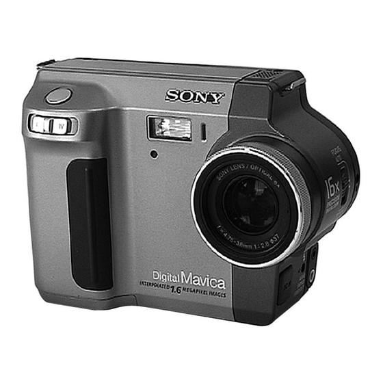
- Page 1 MVC-FD85/FD90 SERVICE MANUAL AEP Model UK Model Level 1 Ver 1.0 2000. 03 Photo: MVC-FD90 SPECIFICATIONS DIGITAL STILL CAMERA...
-
Page 2: Table Of Contents
COMPONENTS IDENTIFIED BY MARK 0 OR DOTTED LINE WITH MARK 0 ON THE SCHEMATIC DIAGRAMS AND IN THE PARTS LIST ARE CRITICAL TO SAFE OPERATION. REPLACE THESE COMPONENTS WITH SONY PARTS WHOSE PART NUMBERS APPEAR AS SHOWN IN THIS MANUAL OR IN SUPPLEMENTS PUBLISHED BY SONY. -
Page 3: Service Note
SERVICE NOTE • NOT FOR REPAIR Make sure that the flat cable and flexible board are not cracked of When remove a connector, don't pull at wire of connector. bent at the terminal. Be in danger of the snapping of a wire. Do not insert the cable insufficiently nor crookedly. - Page 4 [Description on Self-diagnosis Display] Self-diagnosis display • C: ss: ss The contents which can be handled by customer, are displayed. • E: ss: ss Note : The “Self-diagnosis” data is backed up by the coin lithium The contents which can be handled battery.The data will be lost and initialized when the coin lithium by engineer, are displayed.
-
Page 5: Main Parts
(Fig. A) (Fig. B) NP-F330 battery pack (1) Shoulder belt (S) (1) AC-VF10 power adaptor (1) 0 1-475-599-11 (MVC-FD90: AEP, UK model) 3-987-015-01 A-7094-141-A Power cord set (1) (AEP model) 0 1-769-608-11 Power cord (with filter) (1) (UK model) 0 1-783-374-11 Cord connector (A/V) (1) (Fig. -
Page 6: Disassembly
2-2. FC-72 board, Floppy disk drive 2-3. Lens block assembly 2-4. Flash unit, FU-146 board 2-5. DC-IN connector, Microphone UNIT, Control switch block (MF 330)(MVC-FD90) 2-6. Hinge assembly, Battery terminal board, Control switch block NOTE: Follow the disassembly procedure in the numerical order given. -
Page 7: Board, Floppy Disk Drive
Flash unit (10p) qa Cabinet (front) qf Blind sheet block assembly qg Floppy disk drive (4 2 Flexible board (18P) MVC-FD85 FP-231 MVC-FD90 FP-167 6 Claw qd FC Bracket 3 Lens block assembly MVC-FD85 (26P) qs Three screws MVC-FD90 (24P) 2.5) -
Page 8: Lens Block Assembly
8 Two screws 7 Two screws 4 Two screws 2-4. FLASH UNIT, FU-140/146 BOARD 1 ST inslating sheet 6 FU-140 board (MVC-FD90) 2 Two tapping FU-146 board (MVC-FD85) screws (M2 3 Flash unit Short jig (see page 3) 1k . -
Page 9: Dc-In Connector, Microphone Unit
PRECAUTION DURING INSTALLATION 1 Two tapping screws (M2 DC retainer 2 Control switch block (MF 330) 1 Two tapping (MVC-FD90) screws (M2 Cabinet (front) assembly 5 Microphone sheet 2-6. HINGE ASSEMBLY, BATTERY TERMINAL BOARD REMOVING THE CONTROL SWITCH BLOCK (zoom and shutter) -
Page 10: Lcd, Pk-50/52 Board
6 Eight tapping screws (M2 1 Liquid cryst module indicator (24p) 5 PK shield case (lower) assembly 8 Tapping screw (M2 4 Tapping screw (M2 PK-50 board (MVC-FD90) PK-52 board (MVC-FD85) PRECAUTION DURING INSTALLATION Set this knob the center. — 10 —... -
Page 11: Eject Button Section
2-8. EJECT BUTTON SECTION q; Lock button retainer 9 Claw qd Eject knob qa Lock button 5 Pinion gear 6 Parallel pin (DIA. 1.6 qs Lock button 4 Rack (B) spring 2 Gear cover 3 Eject spring 1 Three tapping screws (M2 (PRECAUTION DURING INSTALLATION) Knob... -
Page 12: Repair Parts List
Items marked “*” are not stocked since they • Abbreviation Replace only with part number specified. are seldom required for routine service. Some FD85: MVC-FD85 delay should be anticipated when ordering these FD90: MVC-FD90 items. 2-1-1. CABINET (FRONT) BLOCK SECTION-1 (MVC-FD90) (MVC-FD85) MIC901 Ref. No. -
Page 13: Cabinet (Front) Block Section-2
2-1-2. CABINET (FRONT) BLOCK SECTION-2 (MVC-FD90) J901 (MVC-FD85) supplied not supplied not supplied supplied (MVC-FD90) Ref. No. Part No. Description Remarks Ref. No. Part No. Description Remarks X-3950-245-1 CABINET (FRONT) ASSY (FD90) X-3949-747-1 LABEL ASSY, LENS (FD90) X-3950-606-1 CABINET (FRONT) ASSY (FD85) -
Page 14: Cabinet (Rear) Block Section
2-1-3. CABINET (REAR) BLOCK SECTION not supplied LCD901 ND901 SP901 (Note) Note : Refer to "Eject button section" on page 11 when installing the Rack (A). : BT701(Lithium battery) PK board on the mount position. Ref. No. Part No. Description Remarks Ref. -
Page 15: Lens Block Section
2-1-4. LENS BLOCK SECTION (MVC-FD90) supplied IC101 M901 M903 supplied supplied M902 IC201 supplied M905 supplied M904 supplied (MVC-FD85) Ref. No. Part No. Description Remarks Ref. No. Part No. Description Remarks 1-677-903-11 PWB, FP-231 FLEXIBLE (FD85) not supplied CD-246 BOARD, COMPLETE (FD90) -
Page 16: General
MVC-FD85/FD90 3. GENERAL This section is extracted from instruction manual. — 16 —... -
Page 17: Preparing The Power Supply
— 17 —... -
Page 18: Setting The Date And Time
— 18 —... -
Page 19: Recording Moving Images
— 19 —... -
Page 20: Playing Back Still Images
— 20 —... -
Page 21: Image File Storage Destinations And Image File Names
— 21 —... - Page 22 — 22 —...
- Page 23 — 23 —...
- Page 24 — 24 —...
- Page 25 — 25 —...
- Page 26 — 26 —...
- Page 27 — 27 —...
-
Page 28: Precautions
— 28 —... -
Page 29: Warning And Notice Messages
— 29 —... -
Page 30: Lcd Screen Indicators
MVC-FD85/FD90 Sony Corporation 2000C1620-1 Personal VIDEO Products Company 9-929-813-41 Printed in Japan © 2000.3 — 30 — Published by Safety & Service Engineering Dept.
Need help?
Do you have a question about the MVC-FD90 and is the answer not in the manual?
Questions and answers