Table of Contents
Advertisement
Quick Links
Advertisement
Table of Contents

Related Manuals for BK Precision 5105A


Summary of Contents for BK Precision 5105A
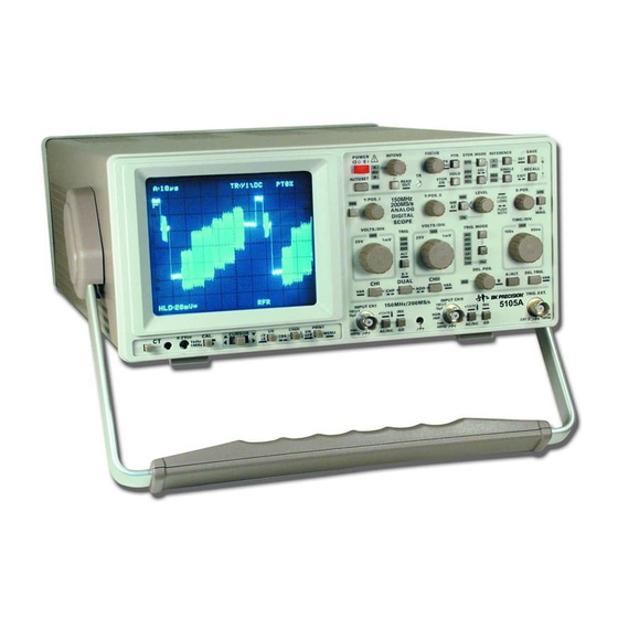
- Page 1 INSTRUCTION ¨ MANUAL MODELS 5105A 150 MHz (200MS/s) ANALOG/DIGITAL OSCILLOSCOPE...
-
Page 2: Table Of Contents
Safety ................38 Testing Transistors ............34 Operation ..............38 In-Circuit Tests ............34 Baud-Rate Setting ............38 Data Communication ..........38 Storage mode ..............34 Signal recording modes ..........35 Front control 5105A ............39 Subject to change without notice... - Page 3 General information regarding the CE marking B&K instruments fulfill the regulations of the EMC directive. The conformity test made by B&K is based on the actual generic and product standards. In cases where different limit values are applicable, B&K applies the severer standard. For emission the limits for residential, commercial and light industry are applied.
-
Page 5: General Information
General Information General Information The case, chassis and all measuring terminals are connected to the protective earth contact of the This oscilloscope is easy to operate. The logical arrangement appliance inlet. The instrument operates according of the controls allows anyone to quickly become familiar with to Safety Class I (three-conductor power cord with the operation of the instrument, however, experienced users protective earthing conductor and a plug with... -
Page 6: Specifications
General Information should be kept in a clean and dry room and must not be operated in explosive, corrosive, dusty, or moist environ- ments. The oscilloscope can be operated in any position, but the convection cooling must not be impaired. The ventilation holes may not be covered. -
Page 7: Type Of Signal Voltage
If a sinusoidal waveform, displayed on the oscilloscope screen, is to be The following description of the 5105A relates to the converted into an effective (rms) value, the resulting peak- analog-oscilloscope mode. Please note “Storage Opera- to-peak value must be divided by 2x√2 = 2.83. -
Page 8: Total Value Of Input Voltage
Type of signal voltage Examples: Set deflection coefficient D = 50mV/div 0.05V/div, observed display height H = 4.6div, required voltage U = 0.05x4.6 = 0.23V Input voltage U = 5V set deflection coefficient D = 1V/div, required display height H = 5:1 = 5div. Signal voltage U = 230Vrmsx 2 ?√... -
Page 9: Connection Of Test Signal
Type of signal voltage set time coefficient Tc = 10µs/div, Calculation of the example in the figure above results in a required wavelength L = 1:(15625x10 ) = 6.4div. signal rise time Sine wavelength L = min. 4div, max. 10div, Frequency F = 1kHz, max. -
Page 10: Controls And Readout
Controls and Readout x10 or x100 attenuator probe is used, no termination is The following description assumes that the instrument is not necessary. In this case, the connecting cable is matched set to “COMPONENT TESTER” mode. directly to the high impedance input of the oscilloscope. When using attenuators probes, even high internal impedance If the instrument is switched on, all important settings are sources are only slightly loaded (approx. - Page 11 Controls and Readout STORAGE MODE ONLY All INTENS settings are stored after the instrument is Additionally, AUTOSET automatically selects refresh switched off. mode (RFR) when SINGLE (SGL) or ROLL (ROL) function is in operation. The AUTO SET function switches the readout on and selects A time base mode (A-LED lit).
- Page 12 when switched back to analog mode, the time base in analog mode will be set to the value selected in the digital mode (e.g. 2µs/div). 2.If a time base between 100s/div and 1s/div has been set in the digital mode and the mode is switched to analog, then the time base in analog mode is automatically set to 500ms/div.
- Page 13 Controls and Readout setting. An additional arrow symbol which points to the by the readout. The only exception is in XY storage left is displayed to indicate post trigger operation. In mode. Then the RFR-LED is lit and the readout displays POST TRIGGER condition the arrow symbol does not XY.
- Page 14 Controls and Readout amplitude variations ( e.g. noise) and frequency variations SINGLE event capturing mode on or off. SINGLE mode (Jitter) are minimized or eliminated in the display. is indicated by the associated SGL-LED. The accuracy of the mean value evaluation increases as SINGLE mode is available in digital as well as in analog the number of signal acquisition scans used for mode and remains unchanged when switching over from...
- Page 15 and will only be terminated later. After termination the In XY mode the switching sequence is: RES-LED extinguishes but the signal display remains. dark – I and II – dark. Briefly pressing the SINGLE pushbutton (RESET function) again restarts a new single event capture which Overwrite then overwrites the previously recorded display.
- Page 16 Controls and Readout time or wait approx. 10 seconds without pressing either suitable position. In ADD mode these conditions apply pushbutton to leave that function. to both channels. After switching GD off and selecting DC input coupling it is possible to determine the DC Attention: content of a signal by comparing the actual Y position Make sure that the signal to be displayed is similar...
- Page 17 Controls and Readout NM - AT selection being set above or below the screen, the symbol Press and hold the pushbutton to switch over from auto- changes and an arrow indicates in which vertical direction matic to normal triggering (NM-LED above the push- the trigger point has left the screen.
- Page 18 Controls and Readout in the opposite direction (ccw.). The available range is selected if any time coefficient from 200µs/div to 50ns/ from 1mV/div up to 20V/div. The knob is automatically div is active. switched inactive if the channel related to it is switched off, or if the input coupling is set to GD (ground).
- Page 19 Controls and Readout STORAGE MODE ONLY Alternate triggering is not available or automatically In XY storage mode the readout indicates “XY” and switched off under the following conditions: the RFR LED (9) is lit. No other STOR. MODE can be chosen.
- Page 20 Controls and Readout Turning the control knob clockwise switches the LED on and extends the hold off time until the maximum is reached (please note “Hold Off-time adjustment”). The hold off time is automatically set to minimum (LED dark), if the A time base setting is changed. The last hold off time setting is stored if alternate (A and B) or B time base mode is selected.
- Page 21 Controls and Readout or CHP) displayed in the readout can be overwritten DEL. POS. (28) control knob continuously (if the B time and changed to the opposite mode. This is carried out base is operated in free run conditions). The difference by simultaneously pressing and holding the CHI (22) and between the start of the A time base trace and the the DUAL (23) pushbutton.
- Page 22 B time base. As the instrument contains a separate trigger unit for the B time base, the BK Precision trigger level and slope can be set independently using the same controls used before for the A time base trigger setting.
- Page 23 The probe symbol should not be activated unless a x10 (10:1) attenuator probe is used. 1.The oscilloscope must be connected to the external B&K interface HO79-6. BK Precision 2.The software version installed in HO79-6 should not be < V2.00. The device used for documentation (e.g. printer, plotter) must be connected with one of the HO79-6 ports.
- Page 24 Controls and Readout ON/OFF ATTENTION! Pressing and holding the pushbutton switches both The following description relates to voltage measure- CURSOR lines on or off. As the cursor lines are part of ment. To avoid misinterpretation, the measurement fun- the readout, they are visible only if the readout is ctions are available only in mono channel operation (chan- switched on.
- Page 25 Controls and Readout (controllable) cursor in the sequence I - II - I, if TRK NOTE: (track) mode is not active. The active cursor is indicated For frequency measurement, the distance between by a continuously dotted line. An interrupted dotted line the cursors must equal exactly one signal period.
-
Page 26: First Time Operation
First Time Operation 1.2 SETUP This menu allows changes to the default settings Each time before the instrument is put into operation check regarding the instrument behavior during operation. that the oscilloscope is connected to protective earth. For The SETUP menu contains the submenus that reason the power cable must be connected to the ”MISCELLANEOUS”... -
Page 27: Adjustment At 1Khz
First Time Operation these requirements when the CAL. pushbutton is depressed. The output provides 0.2V ±1% (tr <4ns) for 10:1 probes. When the Y deflection coefficient is set to 5mV/div, the Connect the probe to CH.I input. Depress the CAL. calibration voltage corresponds to a vertical display of 4 pushbutton for 1MHz. -
Page 28: X-Y Operation
Operating modes of the vertical amplifiers in Yt mode In most cases oscilloscopes are used to display signals in Yt Lissajous figures can be displayed in the X-Y mode for certain mode. Then the signal amplitude deflects the beam in vertical measuring tasks: direction while the time base causes an X deflection (from left to right) at the same time. -
Page 29: Phase Difference Measurement In Dual Mode
Operating modes of the vertical amplifiers in Yt mode For greatest accuracy adjust the time base for slightly over and possibly also using the time vernier (variable) adjustment. one period and approximately the same height of both signals on the screen. The Y deflection coefficients, the time base coefficients and the trigger level setting can be used for this adjustment, without influence on the result. -
Page 30: Automatic Peak (Value) -Triggering
Triggering and time base a sine signal. Except when external trigger is used the trigger When using the internal normal triggering mode, it is possible threshold can be stated as vertical display height in div, at to trigger at any amplitude point of a signal edge, even with which the time base generator starts, the display is stable, very complex signal shapes, by adjusting the trigger LEVEL and the trigger indicator LED lights or flashes. -
Page 31: Triggering Of Video Signals
Triggering and time base signal and the lower frequency range. In most cases, the composite video signal has a high DC NR: Decreases the maximum trigger bandwidth for high content. With constant video information (e.g. test pattern frequency signals. As in DC coupling condition, lower or color bar generator), the DC content can be suppressed frequency signal parts are not affected. -
Page 32: External Triggering
Triggering and time base Even with 180° phase difference between both signals, they cannot trigger the time base. appear with the same slope direction. If signals are applied with a high frequency ratio (difference), the trace intensity Particularly with burst signals or aperiodic pulse trains of the then becomes reduced if the time base is set to smaller time same amplitude, the start of the sweep can be delayed until coefficients (faster sweep). -
Page 33: Auto Set
Auto set the trace end (right side of the screen) are lost when the • Trigger level in electrical midrange position time base speed is increased (time coefficient reduced). The • Y deflection coefficient(s) calibrated X expansion by 10 may also be used, but again the expansion between 5mV/div and 20V/div factor is limited. -
Page 34: Using The Component Tester
Component Tester (analog mode) Testing Capacitors and Inductors quick checks of semiconductors (e.g. diodes and transistors), resistors, capacitors, and inductors. Certain tests can also be made to integrated circuits. All these components can be Capacitors and inductors cause a phase difference between tested individually, or in circuit provided that it is unpowered. -
Page 35: Testing Transistors
In case of doubt, one component terminal may be unsoldered. This terminal should then not be connected to the ground The 5105A contains two 8 bit flash A/D converters with socket avoiding hum distortion of the test pattern. a maximum sampling rate of 100MS/s each. Except in the... -
Page 36: Signal Recording Modes
Storage mode Signals captured and stored in storage mode can be called instrument is adjusted for 25 dots per division. This eases via the built-in RS232 interface for documentation purposes. processing and cursor measurement. For further information please note section “RS232 Interface - Remote Control”. -
Page 37: Alias Signal Display
Test Instructions signal, the maximum frequency to be captured is 20MHz reaching the left hand "stop" of the INTENS. control (parti- (50ns per period). cularly when in XY mode), while with the control at the right hand stop the focus and the line width are just acceptable. Alias signal display With maximum intensity the time base fly-back must on no If, due to the time base setting, the sampling rate is too low,... -
Page 38: Transmission Performance
Test Instructions (DC input coupling). actuation of the Y-POS. controls, the trace positions should have minimal effect on each other. Nevertheless, this cannot Maximum deviations of 0.12div (3%) are permissible. If a be entirely avoided, even in fully serviceable instruments. x10 probe (1%) is connected between the 0.2V output and Y When one trace is shifted vertically across the entire screen, input, the deflection coefficient should be set to 5mV/div. -
Page 39: Time Base
Test Instructions RS232 Interface - Remote Control Component Tester The correct slope of the sync pulse (front edge) must be selected and a suitable time coefficient setting must be chosen. The slope is then valid for both sync frequencies. After selecting component tester mode, a horizontal straight line should appear immediately, when the test leads are not Perfect TV triggering is achieved, when in both display modes connected (open circuit). -
Page 40: Operation
110 baud and 19200 baud. The oscilloscope is then commands and the program SP107 (WINDOWS 3.x, 95 and switched over to REMOTE control mode. The oscilloscope NT 4.0) is supplied with the oscilloscope. Front control 5105A 5105A BK Precision Subject to change without notice... - Page 41 ® 1031 Segovia Circle, Placentia, CA 92870 © 2001 B+K Precision Corp. 481-323-9-001 Printed in U.S.A.
Need help?
Do you have a question about the 5105A and is the answer not in the manual?
Questions and answers