Table of Contents
Advertisement
Quick Links
Advertisement
Table of Contents

Related Manuals for BK Precision 5105B


Summary of Contents for BK Precision 5105B
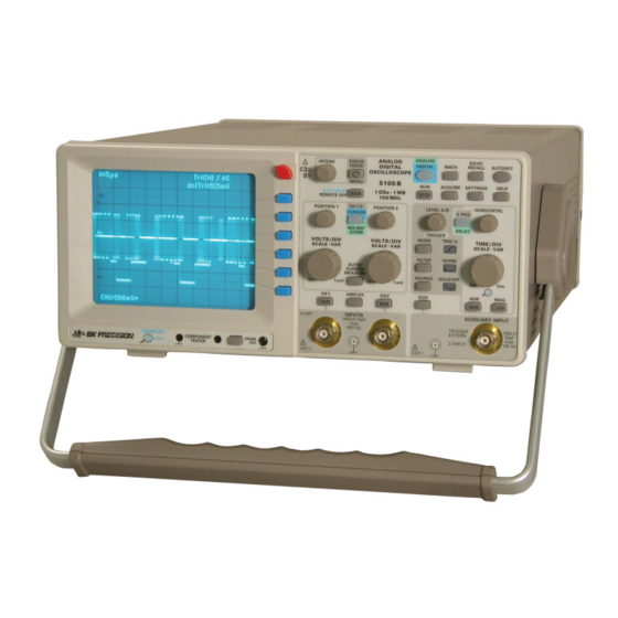
- Page 1 INSTRUCTION MANUAL MODEL 5105B 150MHz (1GS/s) Analog/Digital Oscilloscope...
- Page 2 TEST INSTRUMENT SAFETY WARNING Normal use of test equipment exposes you to a certain amount of danger from electrical shock because testing must sometimes be performed where exposed high voltage is present. An electrical shock causing 10 milliamps of current to pass through the heart will stop most human heartbeats.Voltage as low as 35 volts dc or ac rms should be considered dangerous and hazardous since it can produce a lethal current under certain conditions.
-
Page 3: Table Of Contents
C o n t e n t s Time base B (2nd time base). Delaying, Delayed Sweep. Analog mode. Alternate sweep 150 MHz (1GS/s) Analog/Digital Oscilloscope AUTOSET Specifications Component tester Important hints List of symbols used: CombiScope Positioning the instrument DSO Operation Safety DSO operating modes... -
Page 4: 150Mhz (1Gs/S) Analog/Digital Oscilloscope
150MHz (1GS/s) Analog/Digital Oscilloscope 1 GS/s Real Time Sampling, 10 GS/s Random Sampling Pre-/Post-Trigger -100 % to +400 % 8-Bit Low Noise Flash A/D Converters Time Base 50 s/cm – 5 ns/cm Digital Mode: One complete TV line and a ZOOM mag- nified sector (PAL Burst) 1 MPts memory per channel allows zoom up to 40,000:1 Acquisition modes: Single Event, Refresh, Average, Envelope,... -
Page 5: Specifications
Variable time base A/B: cont. 1:2.5 150 MHz (1GS/s) Analog Digital Oscilloscope 5105B Hold Off time: var. 1:10 LED-Indication Bandwidth X-Amplifier: 0 - 3 MHz (-3 dB) Technical description X-Y phase shift ‹ 3°: ‹ 220 kHz Digital mode Time base range (sequence) -
Page 6: Important Hints
I m p o r t a n t h i n t s prior to connecting any signals. It is prohibited to separate Important hints the safety ground connection. Most electron tubes generate X rays; the ion dose rate of this instrument remains well below the 36 pA/kg permitted by law. -
Page 7: Environmental Conditions
I m p o r t a n t h i n t s Environmental conditions Line voltage Operating ambient temperature: 0 to + 40 degrees C. During The instrument has a wide range power supply from 105 to transport or storage the temperature may be –25 to +55 253 V, 50 or 60 Hz ±10%. -
Page 8: Description Of The Controls
F r o n t P a n e l E l e m e n t s – B r i e f D e s c r i p t i o n VOLTS/DIV-SCALE-VAR (knob) Front Panel Elements – Brief Description Channel 2 Y deflection coefficient, Y variabel and Y scaling setting. - Page 9 ANALOG SAVE/ FOCUS INTENS POWER POWER DIGITAL MATH RECALL AUTOSET TRACE DIGITAL MIXED SIGNAL OSCILLOSCOPE MENU 5105B ACQUIRE SETTINGS HELP · 1 GSa 1 MB EXIT MENU STOP REMOTE OFF 150 MHz CH 1/2 POSITION 1 POSITION 2 LEVEL A/B...
-
Page 10: Basic Signal Measurement
Values of a sine wave signal The oscilloscope 5105B can display all repetitive signals with a fundamental repetition frequency of at least 150 MHz. The frequency response is 0 to 150 MHz (-3 dB). The vertical amplifiers will not distort signals by overshoots, undershoots, ringing etc. -
Page 11: Dc And Ac Components Of An Input Signal
(2.3 ns with the HM1508), trprobe is the rise time of 5105B the probe, e.g. 2 ns. If the signal’s rise time is > 22 ns, the rise times of scope and probe may be neglected. -
Page 12: First Time Operation And Initial Adjustments
F i r s t t i m e o p e r a t i o n a n d i n i t i a l a d j u s t m e n t s impedance sources or low frequencies (<50 kHz). With high First time operation and initial adjustments frequencies impedance matching will be necessary. -
Page 13: Mhz Adjustment
O p e r a t i n g m o d e s o f t h e v e r t i c a l a m p l i f i e r Prior to adjustment make sure that the trace rotation adjust- Operating modes of the vertical amplifier ment was performed. -
Page 14: Xy Operation
O p e r a t i n g m o d e s o f t h e v e r t i c a l a m p l i f i e r case if they can be displayed in these modes. Only then switch to ADD. -
Page 15: Measurement Of Amplitude Modulation
T r i g g e r i n g a n d t i m e b a s e Very small phase differences with moderately high frequencies Set the scope controls as follows in order to display the picture may yield better results with Lissajous figures. -
Page 16: Normal Trigger Mode (See Menu Mode)
T r i g g e r i n g a n d t i m e b a s e even without any input signal. Thus there is always a visible of the vertical position. A positive slope may exist also in the trace in analog mode, and in DSO mode the trace will also be negative portion of a signal. -
Page 17: Frame Sync Pulse Triggering
T r i g g e r i n g a n d t i m e b a s e Frame sync pulse triggering Alternate trigger > Alt. 1/2. The readout Remark: This mode is selected with SOURCE Using frame sync triggering in dual trace chopped mode may will display Tr:alt, but no more the trigger point symbol result in interference, then the dual trace alternate mode indicating level and time position. -
Page 18: Time Base B (2Nd Time Base). Delaying, Delayed Sweep. Analog Mode
T r i g g e r i n g a n d t i m e b a s e After the time base deflected the trace from left to right the the trace from left to right with the speed set with TIME/DIV. trace will be blanked so the retrace is invisible. -
Page 19: Autoset
C o m p o n e n t T e s t e r AUTOSET Component Tester For specific information consult ”Controls and Readout“ AUTO- Specific information can be found in ”Controls and Readout“ under COMPONENT/PROBE and COMPONENT TESTER The following description is valid for both analog and DSO The scope has a built-in component tester. - Page 20 C o m p o n e n t T e s t e r (Sensitive devices like delicate hf transistors etc. should not be tested). The limitation to 10 Vp with bipolar transistors will suffice mostly as usual defects will show up. The best method to verify whether a component is defective is the comparison to a good one.
-
Page 21: Combiscope
1/10 to 1/20 at best. the signals. The 5105B is a 150 MHz 1GS/s Combiscope. – An analog scope has a frequency response which follows With a B&K Combiscope the user is always sure: he needs... -
Page 22: Dso Operation
C o m b i S c o p e 3. Random sampling: 4. Untriggered continuous signal capture, display in XY mode Random sampling is also very old (1952) and also no invention (Menu: trigger MODE): of DSOs. It is similar to equivalent time sampling in that it readout „XY“... -
Page 23: Memory Depth
D a t a t r a n s f e r to 8 times improvement over customary VGA (50 points per zontal line will be shown as each time the same signal point is div) or LCD (25 points per div.) DSO displays. sampled. -
Page 24: Interface, Remote Control
D a t a t r a n s f e r RS232 Interface. Remote control Safety hint: All interface connections are galvanically connected to the scope. Measurements at high potentials are prohibited and endanger the scope, the interface and all gear connected to the interface. If the safety rules are disregarded any damage to B&K products will void the warranty. -
Page 25: General Information Concerning Menu
G e n e r a l i n f o r m a t i o n c o n c e r n i n g M E N U POWER POWER Pushbutton CH I MENU Menu Title AC/DC/50 Ω... -
Page 26: Controls And Readout
ANALOG SAVE/ FOCUS INTENS POWER POWER DIGITAL MATH RECALL AUTOSET TRACE DIGITAL MIXED SIGNAL OSCILLOSCOPE MENU 5105B ACQUIRE SETTINGS HELP · 1 GSa 1 MB EXIT MENU STOP REMOTE OFF 150 MHz CH 1/2 POSITION 1 POSITION 2 LEVEL A/B... -
Page 27: Analog/Digital (Pushbutton Switch)
C o n t r o l s a n d R e a d o u t 4.2 Under remote control this pushbutton will be illuminated. All entries and settings will be automatically stored upon After pressing the pushbutton, control is returned to the front leaving the Mathematics menu or turning the scope off. -
Page 28: Acquire (Pushbutton Switch)
FOCUS INTENS POWER POWER DIGITAL MATH RECALL AUTOSET TRACE DIGITAL MIXED SIGNAL OSCILLOSCOPE MENU 5105B ACQUIRE SETTINGS HELP C H I MENU · 1 GSa 1 MB EXIT MENU STOP REMOTE OFF 150 MHz C/ D C/50 Ω The next step after ”MA5“ causes the display ”Edit“. Calling acquisition may be stopped or started with the RUN/STOP ”Edit“... -
Page 29: Save/Recall (Pushbutton Switch)
C o n t r o l s a n d R e a d o u t The higher the number of acquisitions averaged the lower the Remark: 5 ns/cm are also available in other modes. In Real contribution of a single acquisition will be and the longer the Time Sampling mode and 1 GS/s on one channel each 1 ns a averaging will take. -
Page 30: Settings (Pushbutton Switch)
FOCUS INTENS POWER POWER DIGITAL MATH RECALL AUTOSET TRACE DIGITAL MIXED SIGNAL OSCILLOSCOPE MENU 5105B ACQUIRE SETTINGS HELP C H I MENU · 1 GSa 1 MB EXIT MENU STOP REMOTE OFF 150 MHz C/ D C/50 Ω 9.2.2 Reference Display 10.2.4 Menu Off time... -
Page 31: Help (Pushbutton Switch)
C o n t r o l s a n d R e a d o u t HELP ”Search“. Press the CH1/2–CURSOR–MA/REF–ZOOM- pushbutton , select ”TB B“. The pushbutton will light up Pressing the HELP pushbutton will turn the signal display off green. -
Page 32: Ch1/2-Cursor-Ch3/4-Ma/Ref-Zoom (Pushbutton)
C o n t r o l s a n d R e a d o u t dark: Y position and vertical sensitivity CH1 and CH2. CH 1/2 blue: Y position of cursors. POSITION 1 POSITION 2 CURSOR green: Y position and display height of: –... -
Page 33: Auto / Cursor Measure (Pushbutton Switch)
C o n t r o l s a n d R e a d o u t LEVEL A/B HORIZONTAL X-POS DELAY TRIGGER MODE TRIG ’d TIME / DIV · SCALE AUTO/CURSOR-MEASURE pushbutton FILTER NORM Pressing this pushbutton will open the menu ”Measurement“ which offers the submenus >... -
Page 34: Level A/B Knob
C o n t r o l s a n d R e a d o u t 18.2.1 Auto On Off CH 1/2 POSITION 1 POSITION 2 If Auto is On the result of the automatic measurement will be CURSOR shown in the readout in the top right corner. -
Page 35: Filter (Pushbutton Switch)
C o n t r o l s a n d R e a d o u t as the automatic start will have occurred before the signal arrived. Automatic triggering is possible with or without peak LEVEL A/B HORIZONTAL X-POS detection. -
Page 36: Source (Pushbutton Switch)
C o n t r o l s a n d R e a d o u t 22.1.2 CH2 LEVEL A/B HORIZONTAL Conditions: Analog or DSO mode, ”Edge“ or ”Video“ selected. X-POS CH2 will then be the trigger source, no matter whether it is displayed or not. -
Page 37: Trig'd (Led)
C o n t r o l s a n d R e a d o u t TRIG’d display (not in XY mode) In ”Search“ mode both traces (time base A and B) alternate. Unlike the former time base ”A only“ mode, a sector with This LED will light up if the time base receives a trigger signal. -
Page 38: Hor (Pushbutton)
C o n t r o l s a n d R e a d o u t is selected either ”A variable On Off“ or ”B variable On Off“ LEVEL A/B HORIZONTAL will be shown. The function pushbutton can then be used to X-POS select On/Off. - Page 39 C o n t r o l s a n d R e a d o u t CH 1 VERT/XY CH 2 CH 3/4 INPUTS CH 3 LOGIC CH 4 AUXILIARY INPUT X-INP 1MΩII15pF INPUTS TRIG 1MΩII15pF 400 Vp TRIGGER 1MΩ...
-
Page 40: Ch1 / Var (Pushbutton Switch)
C o n t r o l s a n d R e a d o u t 30.2.1 Off 31.4 Probe submenu In ”Zoom Off“ condition only time base A is active. The readout Pressing the pushbutton will open the ”CH1 probe“ submenu. will thus only show ”A...“... -
Page 41: Ch2 / Var (Pushbutton Switch)
C o n t r o l s a n d R e a d o u t CH 1 VERT/XY CH 2 CH 3/4 LOGIC INPUTS CH 3 CH 4 AUXILIARY INPUT X-INP 1MΩII15pF INPUTS TRIG 1MΩII15pF 400 Vp TRIGGER 1MΩ... -
Page 42: Ch1 (Bnc-Socket)
C o n t r o l s a n d R e a d o u t CH 1 VERT/XY CH 2 CH 3/4 INPUTS CH 3 LOGIC CH 4 AUXILIARY INPUT X-INP 1MΩII15pF INPUTS TRIG 1MΩII15pF 400 Vp TRIGGER 1MΩ... - Page 43 C o n t r o l s a n d R e a d o u t MEMORY COMPONENT PROBE TESTER PROBE ADJ. (connector) A square wave signal of 0.2 V is available for the adjustment of 10:1 probes. The frequency can be selected by pressing the pushbutton ”PROBE ADJ.“...
- Page 44 Limited Two-Year Warranty B&K Precision Corp. warrants to the original purchaser that its products and the component parts thereof, will be free from defects in workmanship and materials for a period of two years from date of purchase. B&K Precision Corp. will, without charge, repair or replace, at its option, defective product or component parts.
- Page 45 Service Information Warranty Service: Please return the product in the original packaging with proof of purchase to the address below. Clearly state in writing the performance problem and return any leads, probes, connectors and accessories that you are using with the device. Non-Warranty Service: Return the product in the original packaging to the address below.
- Page 46 NOTES...
- Page 47 NOTES...
- Page 48 22820 Savi Ranch Parkway Yorba Linda, CA 92887 ©2005 B+K Precision Corp. 481-548-9-001 Printed in U.S.A.
Need help?
Do you have a question about the 5105B and is the answer not in the manual?
Questions and answers