Sign In
Upload
Download
Table of Contents
Contents
Add to my manuals
Delete from my manuals
Share
URL of this page:
HTML Link:
Bookmark this page
Add
Manual will be automatically added to "My Manuals"
Print this page
×
Bookmark added
×
Added to my manuals
Manuals
Brands
Samsung Manuals
Refrigerator
RS 24
Service manual
Samsung RS 24 Service Manual
Side-by-side refrigerator
Hide thumbs
1
2
3
4
5
6
7
8
9
10
11
12
13
14
15
16
17
18
19
20
21
22
23
24
25
26
27
28
29
30
31
32
33
34
35
36
37
38
39
40
41
42
43
44
45
46
47
48
49
50
51
52
53
54
55
56
57
58
59
60
61
62
63
64
65
66
67
68
69
70
71
72
73
74
75
76
77
78
79
80
81
82
page
of
82
Go
/
82
Contents
Table of Contents
Bookmarks
Table of Contents
Table of Contents
Important Safety Notice
Introduction
Installation
Nomenclature
Specifications
Interior Views and Dimensions
Refrigeration Cycle and Cool Air Circulation Route
7. Mechanical Disassembly
Mechanical Disassembly
7-1) Refrigerator Disassembly
Beverage Station
Control Panel
Door Gasket
Door Handle
Gallon Door bin
Plastic Drawers in Refrigerator
Refrigerator Door Light Switch
Refrigerator Light
Tempered Glass Shelf
Evaporator Cover in the Refrigerator
Evaporator Fan Motor
Upper Ductwork
Water Filter
Coolselect Zone Thermistor
Evaporator in Refrigerator
Refrigerator Thermistor
7-2) Freezer Disassembly
Door bin in Freezer
Freezer Door Light Switch
Plastic(Wire) Drawer in Freezer
Freezer Shelf
Ice Dispenser Ice Maker
Auger Motor Case
Freezer Light
Evaporator Cover in Freezer
Upper Ductwork
Evaporator Fan Motor
Evaporator in Freezer
Freezer Thermistor
Ambient Thermistor
Ice-Makerthermistor
7-3) Machine Compartment Disassembly
Machine Compartment Electrix Box
Water Solenoids
Condenser Fan
Sub-Condenser
Operation Function
8-2) Temperature Control Function
8-3) Power Freeze and Power Cool Functions
8-4) Child Lock Function
8-5) Ice Water Dispenser Function
8-6) C-Fan Motor Delay Function of the Machine Compartment
8-7) Coolselect Zone
Function(Optional)
8-8) Water Filter Indicator Function
8-9) Ice-Maker Function
8-10) Defrost Function
8-11) Forced Operation Function (Pull-Down/R-Defrost/R,F-Defrost/Cancellation)
8-12) Sound Function
8-13) Exhibition Function
8-14) Self-Diagnostics Function
Self-Diagnostics Check List
8-15) Load Operation Check Function
8-16) Restoration Function for Power Outage
8-17) Set Point Shift Function
8-18) Table of Set Point Shift Function
Circuit Descriptions
9-1) Source Power Circuit
9-2) Oscillator Circuit
9-3) Reset Circuit
9-4) Door S/W Sensing Circuit
9-5) Temperature Sensing Circuit
9-6) Key Scan and Display Circuit
9-7) Coolselect Zone
Panel Circuit
9-8) Fan Motor(BLDC) Drive Circuit
9-10) Option Circuit
9-11) Load Drive Circuit
9-9) EEPROM Circuit
Diagnostics
Illustrated Parts Catalog
Safety Instruction on Services
Appendix Ⅰ Ⅰ (Reference for Circuit Diagnostics)
Appendix Ⅱ Ⅱ (Circuit Diagram)
Advertisement
Quick Links
Download this manual
For the latest parts information,
Please access to our service web site
(http://www.e4buyer.com/refrigerator)
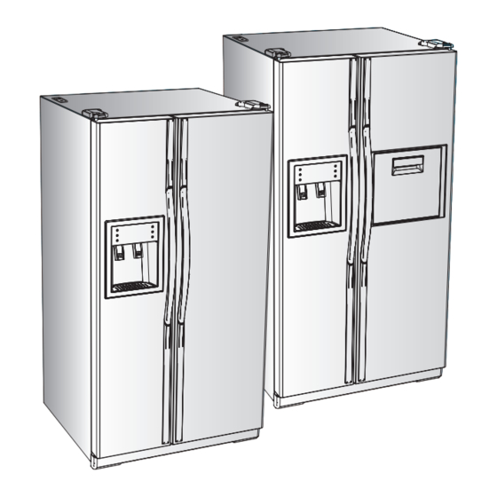
SIDE-BY-SIDE REFRIGERATOR
SAMSUNG Home Appliance Service
Model:
RS 24 ***
RS 25 ***
RS 26 ***
RS 27 ***
Table of
Contents
Previous
Page
Next
Page
1
2
3
4
5
Advertisement
Chapters
Table of Contents
3
7. Mechanical Disassembly
12
Operation Function
22
Circuit Descriptions
37
Table of Contents
Need help?
Do you have a question about the RS 24 and is the answer not in the manual?
Ask a question
Questions and answers
Related Manuals for Samsung RS 24
Refrigerator Samsung Model RS27KLMR Owner's Manual And Installation
Side by side refrigerator (36 pages)
Refrigerator Samsung RS2577SL Owner's Manual And Installation
(60 pages)
Refrigerator Samsung RS Owner's Manual And Installation
Samsung side by side refrigerator owner's manual and installation (16 pages)
Refrigerator Samsung RS20NCSL Service Manual
(59 pages)
Refrigerator Samsung RS2531 series Owner's Manual And Installation
Samsung refrigerator owner's manual (40 pages)
Refrigerator Samsung RS263B Series User Manual
(32 pages)
Refrigerator Samsung RS261MDBP User Manual
Rs261m series (32 pages)
Refrigerator Samsung RS22HDHPNSR User Manual
(41 pages)
Refrigerator Samsung RS25H5121 SERIES User Manual
(120 pages)
Refrigerator Samsung RS25H50 Series User Manual
Refrigerator (96 pages)
Refrigerator Samsung RS21 Service Manual
(98 pages)
Refrigerator Samsung RS-21 KLMR User Manual
(49 pages)
Refrigerator Samsung RS25J50 User Manual
(33 pages)
Refrigerator Samsung RS25J50 User Manual
(120 pages)
Refrigerator Samsung Refrigerator User Manual
(116 pages)
Refrigerator Samsung RS22T5201SR User Manual
(68 pages)
This manual is also suitable for:
Rs 25
Rs 27
Rs 26
Table of Contents
Save PDF
Print
Rename the bookmark
Delete bookmark?
Delete from my manuals?
Login
Sign In
OR
Sign in with Facebook
Sign in with Google
Upload manual
Upload from disk
Upload from URL


Need help?
Do you have a question about the RS 24 and is the answer not in the manual?
Questions and answers