Honda EB3500X Owner's Manual
Honda portable generator owner's manual
Hide thumbs
Also See for EB3500X:
- Owner's manual (60 pages) ,
- Owner's manual (45 pages) ,
- Owner's manual (53 pages)
Table of Contents
Advertisement
Advertisement
Table of Contents

Related Manuals for Honda EB3500X


Summary of Contents for Honda EB3500X
- Page 2 The generator is a potential source of electrical shock if misused. Do not expose the generator to moisture, rain or snow. Do not let the generator get wet, and do not operate it with wet hands.
- Page 3 This manual contains the information on how to do that; please read it carefully. This owner’s manual discribes the operation and maintenance of the EB3500X Honda Generator. All information in this publication is based on the latest product information available at the time of printing.
-
Page 4: Table Of Contents
CONTENTS SAFETY ... Safety Label Locations ... Safety Information ... COMPONENT IDENTIFICATION CONTROLS ... Engine Switch ... Recoil Starter ... Fuel Valve ... Choke Rod ... Circuit Breaker ... Ground Terminal ... Oil Alert System ... system ... Auto-throttle Circuit Protector Ground Fault Circuit Interrupter (GFCI) Receptacle ... - Page 5 MAINTENANCE Maintenance Schedule Tool Kit..Engine Oil Change..Air Cleaner Service ... Fuel Sediment Cup Cleaning ... Spark Plug Service Spark Arrester Maintenance TRANSPORTING/STORAGE.. TROUBLESHOOTING WIRING DIAGRAM..SPECIFICATIONS OF OPTIONAL PARTS ... INSTALLATION CUSTOMER SERVICE INFORMATION.. INDEX..
-
Page 6: Safety
SAFETY SAFETY LABEL LOCATION These labels warn you of potential hazards that can cause serious injury. Read them carefully. If label comes off or becomes hard to read, contact your Honda Generator dealer for a replacement. RNlNG DO NOT USE INDOORS. EXHAUST GAS CONTAINS POISONOUS CARBON MONOXIDE. - Page 7 - EB3500X HONDAMO CAUTION BE SURE TO FILL CRANKCASE _.-._--- __- WITH RECOMMENDED BEFORE USING FOR DETAILED EXPLANATION, SEE THE OWNER’S MANUAL. ,TOR LTD. co.. MADE IN JAPAN VOLTAGE 12Ol24OV FREQUENCY 60Hz RATED OUTPUT 3.0kVA MAX. OUTPUT 3.5kVA PHASE FUEL GASOLINE...
-
Page 8: Safety Information
SAFETY INFORMATION Honda generators are designed operated according to instructions. Read and understand this owner’s manual before operating your generator. You can help prevent accidents by being familiar with your generator’s procedures Operator Responsibility Know how to stop the generator quickly in case of emergency. Understand the use of all generator controls, output receptacles, connections. - Page 9 Fire and Burn Hazards The exhaust system gets hot enough to ignite some materials. Keep the generator at least 1 mater (3 feet) away from buildings and other equipme.nt during operation. - ,Do not enclose the generator in any structure. Keep flammable materials away from the generator.
-
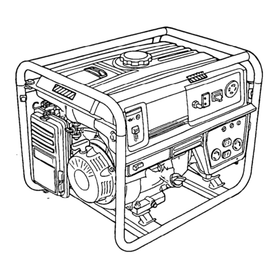
Page 10: Component Identification
COMPONENT IDENTIFICATION VOLTAGE SELECTOR SWITCH ENGINE SWIT RECEPTACLES GROUND TERMINAL GFCI RECEPTACLE OIL FILLER CAP AUTO-THROTTLE SWITCH OIL DRAIN PLUG ENGINE SERIAL NUMBER... - Page 11 FUEL TANK CAP OCCUP ANTS IGFCI) TEST RI ECOlib ’ Record the engine and frame serial numbers for your future reference. Refer to these serial numbers when ordering parts, and when making technical or warranty inquiries (see page 44) Frame serial number: Engine serial number: FUEL METER FRiME...
-
Page 12: Controls
CONTROLS Engine Switch To start and stop the engine Switch position: OFF: To stop the engine. To run the engine. Recoil Starter To start the engine, pull the starter grip lightly until resistance is felt, then pull briskly.. Do not allow the starter engine.Return it gently to prevent damage to the starter. -
Page 13: Fuel Valve
Fuel Valve The fuel valve is located between the fuel tank and carburetor. When the valve lever is in the ON position, fuel is allowed to flow from the fuel tank to the carburetor. Be sure to return the lever to OFF after stopping the engine. Choke Rod The choke is used to provide proper starting mixture when the engine is cold. -
Page 14: Circuit Breaker
Circuit Breaker The circuit breaker will automatically switch OFF if there is a short circuit or a significant overload of the generator at the receptacle. If the circuit breaker is switched OFF automatically, and does not exceed the rated load capacity of the circuit before switching the circuit breaker ON again. -
Page 15: Auto-Throttle System
Auto-throttle System The auto-throttle system automatically are turned off of or disconnected. When appliances are turned on or reconnected, the engine returns to the rated speed. AUTO: Recommended to minimize fuel consumption noise levels when no load is applied to the generator. OFF: The auto-throttle system does not operate. -
Page 16: Ground Fault Circuit Interrupter (Gfci) Receptacle
Ground Fault Circuit Interrupter (GFCI) Receptacle Using the generator in rain, snow or near water can lead to death from electric shock. Keep the genetator dry. All of the 20 ampere 120 volt receptacles on the generator are protected by a Ground Fault Circuit Interrupter (GFCI) for protection against the hazards of ground fault currents. - Page 17 INSPECTION Perform the tests below to ensure proper operation of the GFCI. Record your test on the GFCI test card provided on the generator. Before each use: If the generator is stored outdoors, unprotected from the weather, test the GFCI receptacle before each use as described in the monthly inspection. Monthly: Under normal operating conditions, perform the GFCI test monthly.
- Page 18 6. Press the RESET BUTTON The RESET BUTTON should be flush with the test button. If the RESET BUTTON is not flush with the TEST BUTTON. contact an authorized Honda generator dealer. 7. When the RESET BUTTON extends during operation: Unplug all appliances from the GFCI protected receptacle.
-
Page 19: Voltage Selector Switch (Dual Voltage System)
Voltage Selector Switch (Dual Voltage System) The voltage selector switches the main power carrying windings generator to produce “12OV ONLY” or “120/24OV”. If a 240V appliance is connected to the 4-prong receptacle, the switch must be in the “120/24OV” position. If a 12OV appliance ONLY is being connected to any of the 12OV 3-prong receptacles, select the “120V ONLY”... -
Page 20: Generator Use
GENERATOR USE Connections to a Building’s Connections for standby power to a building’s electrical system must be made by a qualified electrician. The connection must isolate the generator power from utility power, and must comply with all applicable laws and electrical codes. -
Page 21: Ac Applications
AC Applications Before connecting an appliance or power cord to the generator: Make sure that it is in good working order. Faulty appliances or power cords can create a potential for electrical shock. If an appliance begins to operate abnormally, becomes sluggish or stops suddenly, turn if off immediately. -
Page 22: Ac Operation
AC Operation 1. Start the engine (refer to page 27). 2. Turn the voltage selector switch to either position. With the voltage selector switch in the “1201240 V” position, you can use the 120 V and 120/240 V receptacles simultaneously. 120/240 V receptacle, receptacle, then select the “120 V ONLY”... -
Page 23: Ac Receptacle Selection
AC Receptacle Selection The generator has two separate main power producing circuits. These two circuits supply equal power to receptacles shown when the voltage selector switch is in the 120/240 V position. When two or more receptacles are used; prevent overloading by dividing the load between the two power circuits. -
Page 24: Auto-Throttle System
Auto-throttle system With the switch in the AUTO position, engine speed is automatically when ALL loads are turned OFF or disconnected. When appliances are turned ON or reconnected, the engine returns to rated speed. In the OFF position, the auto-throttle system does not operate. -
Page 25: High Altitude Operation
High Altitude Operation At high altitude, the standard carburetor air-fuel mixture will be excessively rich. Performance will decrease, and fuel consumption High altitude performance can be improved by installing a smaller diameter main fuel jet in the carburetor and readjusting the pilot screw. If you always operate the engine at altitudes higher than 6,000 feet above sea level, have an authorized Honda generator dealer perform this carburetor modification. -
Page 26: Pre-Operation Check
PRE-OPERATION CHECK Engine oil (NoTlCEj Engine oil is a major factor affecting engine performance and service life. Non-detergent engine and are not recommended. Check the oil level BEFORE EACH USE with the generator on a level surface with the engine stopped. Use Honda 4-stroke equivalent high detergent, premium... -
Page 27: Fuel Recommendation
Fuel Recommendation 1. Check the fuel level gauge. 2. Refill the tank if the fuel level is low. Do not fill above the shoulder of the fuel strainer. Gasoline is extremely flammable and is explosive conditions. Refuel in a well-ventilated smoke or allow flames or sparks in the area where the engine is refueled or where gasoline is stored. -
Page 28: Mtbe (Methyl Tertiary Butyl Ether)
Occasionally you may hear light “spark knock” or “pinging” (metallic rapping noise) while operating under heavy loads. This is no cause for concern. If spark knock or pinging occurs at a steady engine speed, under normal load, change brands of gasoline. authorized Honda generator dealer. -
Page 29: Starting The Engine/Stopping The Engine
Starting the Engine 1. Make sure that the AC circuit breaker is in the OFF position. The generator may be hard to start if a load is connected. 2. Turn the fuel valve to the ON position. 3. Pull the choke rod to the CLOSE position. 4. -
Page 30: Maintenance
MAINTENANCE Periodic maintenance and adjustment is necessary to keep the generator in good operating condition. Perform the service and inspection at the intervals shown in the Maintenance Exhaust gas contains poisonous Shut off the engine before performing any maintenance. must be run, make sure the area is well ventilated. 1 NOTICE-1 U se only genuine HONDA parts or their equivalent maintenance... -
Page 31: Tool Kit
Tool kit The tools supplied with the generator will help you to perform the owner maintenance procedures listed on the following page. Always keep this tool kit with the generator. 10 x 12 mm WRENCH SCREW DRIVER PLUG WRENCH DRIVER HANDLE HANDLE BAR TOOL BAG... -
Page 32: Engine Oil Change
Engine oil change Drain the oil while the engine is warm to assure complete and rapid draining. 1. Remove the drain plug and sealing washer, oil filler cap, and drain the oil. 2. Install the drain plug and sealing washer. Tighten the plug securely. 3. -
Page 33: Air Cleaner Service
Air cleaner service A dirty air cleaner will restrict air flow to the carburetor. To prevent carburetor malfunction, service the air cleaner regularly. Service more frequently when operating the generator in extremely dusty areas. Using gasoline or flammable solvent to clean the filter element can cause a fire or explosion. -
Page 34: Fuel Sediment Cup Cleaning
Fuel Sediment Cup Cleaning The sediment cup prevents dirt or water which may be in the fuel tank from entering the carburetor. sediment cup should be cleaned. 1. Turn the fuel valve to the OFF position. Remove the sediment cup, O-ring, and filter. -
Page 35: Spark Plug Service
Spark Plug Service Recommended spark plugs: To ensure proper engine operation, the spark plug must be properly gapped and free of deposits. If the engine has been running, the muffler will be very hot. Be careful not to touch the muffler. 1. -
Page 36: Spark Arrester Maintenance
6. Check that the spark plug washer is in good condition, and thread the spark plug in by hand to prevent cross-threading. 7. After the spark plug in seated, tighten with a spark plug wrench to compress the washer. If installing a new spark plug, tighten l/2 turn after the spark plug seats to compress the washer. -
Page 37: Transporting/Storage
When transporting the generator, turn the engine switch and the fuel valve OFF. Keep the generator level to prevent fuel spillage. Fuel vapor or spilled fuel may ignite. Contact with a hot engine or exhaust system can cause serious burns or fires. Let the engine cool before transporting the generator. - Page 38 1. Drain the carburetor by loosening the drain screw. Drain the gasoline into a suitable container. Gasoline is extremely conditions. Perform this task in a well ventilated area with the engine stopped. Do not smoke or allow flames or sparks in the area during this procedure.
-
Page 39: Troubleshooting
TROUBLESHOOTING When the engine will not start: Is there enough oil in NO the engine? Is there a spark from NO the spark plug? there is no spilled fuel around the spark plug. Spilled fuel may ignite. does not start, take the generator to an authorized... - Page 40 No electricity at the AC receptacles: DEFECTS...
-
Page 41: Wiring Diagram
WIRING DIAGRAM... -
Page 42: Specifications
242 cc (14.8 cu in) [73 x 58 mm (2.9 x 2.3 in)] 1 .l JZ (1.16 US qt, 0.97 Imp qt) 17.0 1 (4.5 US gal, 3.74 Imp gal) BPR5ES (NGK), WlGEPR-U are subject to change EB3500X 62 kg (136.7 lb) GX240Ki 8.2 : 1 3,600 r.p.m. Forced air... -
Page 43: Installation Of Optional Parts
INSTALLATION OF OPTIONAL PARTS Hanger Kit Installation 8 x 16 mm FLANGE BOLT (4) HANGER 1. Position the hanger at the generator’s balance point, in the middle of the fuel tank. 2. Fit the end tabs of the hanger through the bracket slots, and bolt the brackets to the hanger. - Page 44 4 Wheel Kit Installation Install the four wheels on the axle shaft. 2. Install the assembly to the generator using four bolts and nuts. WHEEL StOPPER NOTE: Install the shaft with wheel stopper facing engine Inside Shorter side.
- Page 45 2 Wheel kit Installation 1. Install the two wheels on the axle shaft. 2. Install the axle assembly on the generator using four bolts and nuts. 3. Install the two stands using four bolts and nuts. 4. Install right and left handles on the generator upper frame using brackets and six bolts.
-
Page 46: Customer Service Information
Manager can help. Almost all problems are solved in this way. If you are dissatisfied with the decision made by the dealership’s ment, contact the Honda Power Equipment Customer Service Office. You can write to: American Honda Motor Co., Inc. -
Page 47: Index
COMPONENT IDENTIFICATION CONTROLS ... system ... Auto-throttle Choke Rod ... Circuit Breaker ... Circuit Protector ... Engine Switch ... Fuel Valve ... Ground Fault Circuit Interrupter (GFCI) Receptacle ... Ground Terminal ... Oil Alert System ... Recoil Starter ... Voltage Selector Switch (Dual Voltage System) ..17 CUSTOMER SERVICE INFORMATION ... - Page 48 INDEX SPEClFltiATlONS STARTING THE ENGINE/STOPPING TRANSPORTING/STORAGE.. TROUBLESHOOTING WIRING DIAGRAM..THE ENGINE ...
- Page 49 MEMO...
- Page 50 MEMO...
Need help?
Do you have a question about the EB3500X and is the answer not in the manual?
Questions and answers