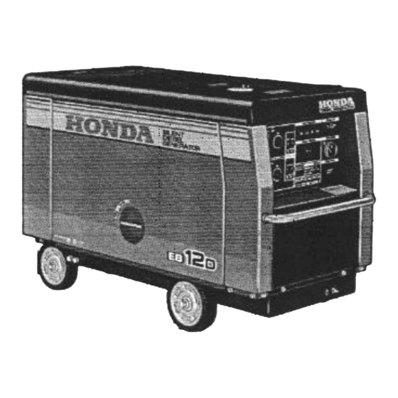
Honda EB12D Owner's Manual
Hide thumbs
Also See for EB12D:
- Owner's manual (52 pages) ,
- Owner's manual (68 pages) ,
- Parts list (13 pages)
Table of Contents
Advertisement
Quick Links
Advertisement
Table of Contents

Related Manuals for Honda EB12D


Summary of Contents for Honda EB12D
- Page 3 This manual is a permanent part of the generator, and it must stay with the generator if resold. The Honda EB12D generator is not factory equipped with a spark arrester. In some areas, it is illegal to operate an engine...
-
Page 4: Table Of Contents
CONTENTS ............1. SAFETY INFORMATION ..........2. COMPONENT IDENTIFICATION ............... 3. CONTROLS ..............Engine switch ..............Circuit breaker ............... Circuit protector ....Ground Fault Circuit Interrupter (GFCI) Receptacle ............... Fuel meter ..............Hour meter ..............Indicator lights ........... 4. PRE-OPERATION CHECKS ........ -
Page 5: Safety Information
I. SAFETY INFORMATION SAFETY INFORMATION For your safety and the safety of others, pay special attention to these precautions: Operator Responsibility Know how to stop the generator quickly in case of emergency. Unders- tand generator controls, output receptacles, connections. Be sure that anyone operates the generator... - Page 6 WARNING LABEL LOCATION Read these labels before operating the generator. Your Honda generator comes with several labels containing important safety information. Anyoune uses the generator should read and understand this information before operating the generator. The labels should be considered as permanent parts of the generator.
-
Page 7: Component Identification
2. COMPONENT IDENTIFICATION EXHAUST OUTLET COOLING AIR OLJTLET LIFTIYG HOOK FUEL FILLER CAP TEST RECORD MAINTENANCE COVE MAINTENANCE COVER ENGINE OIL FILLER CAP PANEL OOLANT RESERVE TANK TTERY OIL LEVEL GAUG )OLANT DRAIN BOL ENGINE OIL DRAIN BOLT FRAME SERIAL NLkMBER ’... - Page 8 CIRCUIT PROTECTOR-2OA AC RECEPTACLES 20A 120V CIRCUIT PROTECTOR-30A AC RECEPTACLE 30A 12OV INDICATOR LIGHTS ENGINE VITCH : FUEL METER TACLE 50A AC I CIRdIT BREAKER IU iR METER 1201 I24OV AC RECEPTACLk 120124OV CIRCUIT PROTECTOR-30A CIRCUIT PROTECTOR-BOA...
-
Page 9: Controls
3. CONTROLS Engine Switch To start and stop the engine. Key position: OFF: To stop the engine. Key can be removed/inserted. To run the engine after starting. START: To start the engine by turning the starter motor. Return the key to the ON position once the engine has started. -
Page 10: Circuit Breaker
Circuit Breaker The circuit breaker protects the individual circuit protectors and the 50A 120/24OV receptacle. The circuit breaker will automatically switch OFF if the circuit is overloaded or the appliance plugged into the circuit is faulty. If the circuit breaker is switched OFF automatically, check... -
Page 11: Ground Fault Circuit Interrupter (Gfci) Receptacle
Ground Fault Circuit Interrupter (GFCI) Receptacle Using the generator in rain, snow or near water can lead to death from electric shock. Keep the generator dry. This receptacle is protected by a Ground Fault Circuit interrupter (GFCI) for protection against electrical shock. -
Page 12: Fuel Meter
Fuel Meter Indicates the amount of fuel in the fuel tank when the engine switch is in switch to the OFF position and refill the the ON position. Turn the engine fuel tank when the needle is near the “E” mark. -
Page 13: Indicator Lights
If the oil pressure indicator light continues to light even though engine oil level is correct, stop operating the generator and see an authorized Honda generator dealer. COOLANT TEMPERATURE INDICATOR LIGHT OIL PRESSURE INDICATOR LIGHT Coolant Temperature Light Lights when... - Page 14 If the light comes on after the engine has been restarted and the engine stops automatically, discontinue operation of the generator and contact an authorized Honda generator dealer. CHARGE INDICATOR LIGHT GENERATOR INDICATOR LIGHT Charge Indicator Light charge indicator light comes engine...
-
Page 15: Pre-Operation Checks
4. PRE-OPERATION CHECKS Check these items before starting the generator. Be sure the generator on a level surface. Block the wheels if the optional wheel kit is installed. Maintenance Cover Opening and Closing To open: 1. Turn the maintenance cover opening knob to the OPEN position and pull up on the cover. -
Page 16: Engine Oil
Engine En gine oil is a major factor affecting engine performance service life. Running the engine with insufficient oil can cause serious engine damage. Non-detergent 2-stroke engine recommended. Be sure to check the engine oil on a level surface with the engine stopped and the wheels... -
Page 17: Fuel
Fuel Fuel tank capacity: 38 lit. (IO US gal, 8.4 Imp. gal1 Turn the engine switch ON and check the fuel meter. Refill the tank to the upper level if necessary. Do not fill the fuel tank above the upper level mark. Use ONLY clean high-quality fuel. - Page 18 NOTE: Depending on the season and the ambient temperature, a different grade of diesel fuel should be used. If a summer grade fuel is used in the winter, the summer fuel may freeze preventing the engine from star- ting. Winter grade fuel is used in the summer could result...
-
Page 19: Coolant
Coolant Open the maintenance cover (see page 13). Check the coolant level in the reserve tank when the engine is at normal operating temperature. If the level is near the MIN level, add coolant to bring it up to the MAX level (see page 18 for coolant recommendation). -
Page 20: Fuel Filter
Coolant Recommendation Use high quality ethylene glycol antifreeze that is specifically formulated for use in aluminum engines. Mix the antifreeze with low-mineral drinking water or distilled water. A 50/50 mixture of ethylene glycol antifreeze and water is recommended for most temperature and provides good corrosion brotection. -
Page 21: Battery
Battery The electrolyte level must be kept between the UPPER and LOWER level marks. If the electrolyte level is near the LOWER level, remove the battery filler caps and carefully add distilled water to the upper level line (see page 38). -
Page 22: Indicator Lights
OFF position. If the indicator light(s) does not come on, or do not go out after 4 seconds with the engine switch in the ON position, contact an authorized Honda generator dealer. ENGINE SWITCH INDICATOR LIGHTS... -
Page 23: Starting And Stopping The Engine
5. STARTING AND STOPPING THE ENGINE Starting the engine Before starting the engine disconnect any load from the AC receptacle. 1. Open the maintenance cover (see page 13) and turn the fuel valve to the ON position. 2. Close the maintenance cover (see page 13). - Page 24 4. Insert the key and turn the engine switch to the ON position. If the am- bient temperature is below freezing, wait for the indicator lights to go OFF before turning the key to the start position. This allows the glows plug to pre-heat the combustion chambers.
- Page 25 6. After the engine starts, let the engine switch return to the ON position. 7. Warm the engine for 2 or 3 minutes before applying a load to the generator. Blue smoke might be emitted from the exhaust during warm-up. This is a normal occurrence.
-
Page 26: Stopping The Engine
Stopping the engine In an emergency: Turn the engine switch to the OFF position. -ENGINE SWITCH In normal use: 1. Turn all electrical appliance’s connected to the generator OFF. 2. Turn the AC circuit breaker OFF. AC CIRCUIT BREAKER... - Page 27 3. Turn the engine switch to the OFF position. ENGINE SWITCH 4. Open the maintenance cover (see page 13) and turn the fuel valve to the OFF position.
-
Page 28: Generator Use
6. GENERATOR Connections to a Building’s Electrical System If the generator will be used as an alternative to utility company power, isolation switch must be installed to disconnect the utility lines from the building when the generator is connected. Installation must be performed by a qualified electrician... - Page 29 AC Applications Make sure all appliances are in good working order before connecting them to the generator. If an appliance begins to operate abnormally, becomes sluggish, or stops suddenly, turn it off immediately. Disconnect the appliance, and determine whether the problem is the appliance, or the rated load capacity...
- Page 30 GFCI receptacles. Start the engine. Turn the circuit breaker CIRCUIT BREAKER -The RESET BUTTON should extend Press the TEST BUTTON with a click. the RESET BUTTON does not ex- tend, contact an authorized Honda generator dealer.
- Page 31 GFCI protected receptacle. Press the RESET BUTTON. IF THE GFCI CAN NOT BE RESET: The GFCI is faulty. Contact an autho- rized Honda generator dealer. Check the appliance or its cord. IF THE GFCI RESETS PROPERLY:...
- Page 32 Operation 1. Start the engine (see page 21). 2. Switch the AC circuit breaker CIRCUIT BREAKER 3. Plug the appliance into the appropriate AC receptacle.
- Page 33 How to use the receptacle When two or more receptacles are used, refer to the table below and apply the load to each receptacle equally to prevent overloading. Voltage fluctuation can be prevented by applying the load equally to the single phase receptacles.
-
Page 34: Maintenance
Honda parts their equivalent maintenance and repair. Parts of lower quality may damage the engine. Tool kit The tools necessary for performing... -
Page 35: Maintenance Schedule
Schedule NOTE: (1) Service more frequently when used in dusty areas. (2) These items should be serviced by an authorized HONDA generator dealer unless the owner has the proper tools and is mechanically proficient. See the Shop Manual. (3) For professional... -
Page 36: Engine Oil Change
Engine oil change Drain oil while the engine is warm to assure complete and rapid draining. 1. Open the maintenance cover (see page 13). 2. Remove the oil filler cap and drain plug to drain the oil. 3. After draining is complete, check that... -
Page 37: Air Cleaner
Air cleaner If you operate the generator in very dusty areas, check and replace the air cleaner more often than specified in the MAINTENANCE SCHEDULE. Operating the engine without ttie air cleaner will cause rapid engine wear. 1. Open the maintenance cover (see page 13). - Page 38 4. Install the element, inner cover and air cleaner cover in the reverse order of removal. NOTE: Install the cover with the UP mark facing up and align the tabs of the inner cover and the air cleaner cover with the cutout of the air cleaner case.
-
Page 39: Fuel Filter
Fuel filter Diesel fuel is extremely flammable and explosive under certain condition. Do not smoke or allow flames or sparks in the area. 1. Open the maintenance cover (see page 13). 2. Turn the fuel valve to the OFF position. 3. -
Page 40: Battery
Honda generator dealer. Open the maintenance cover and check the electrolyte level in each bat- tery cell. Fill the battery with distilled water to the upper level line. Never overfill the battery. - Page 41 Battery cleaning If the battery terminals are contaminated or corroded, remove the battery and clean the terminals. Removal: 1. Remove the battery set plate. 2. Disconnect the negative (-1 battery cable first, then disconnect positive (+) battery cable. 3. Remove the battery.
-
Page 42: Fuse Replacement
If a main fuse is blown, see an authorized Honda generator dealer. SUB FUSE MAIN FUSE 1 NOTICE 1 Ne ver use a fuse with a different... -
Page 43: Transporting And Storage
8. TRANSPORTING AND STORAGE The engine becomes very hot during operation and remains hot for a while after stopping. Allow the engine to cool before transporting or storing indoors. Transporting Contact with a hot engine or exhaust system can cause serious burns or fires. - Page 44 Before storing the generator for an extented period: 1. Be sure the storage area is free of excessive humidity and dust. 2. Clean the generator. 3. Check the generator according to the maintenance schedule (see page 33) and repair/replace any items as necessary.
-
Page 46: Specifications
10. SPECIFICATIONS Dimensions EBI 2D Model Description Length x Width x Height 139Ox630x815mm (54.7 x 24.8 x 32.1 Dry weight 340 kg (701 Engine Model GDI 100 Type 4 stroke OHC 3 cylinder water cooled diesel Displacement 1061 [Bore x Stroke1 [76 x 78 mm (3.0 x 3.1 in)1 Rated output... -
Page 48: Warranty Service
Your purchase of Honda product is greatly appreciated by both your dealer and American Honda Motor Co., In. We want to assist you in every... - Page 49 When you write or call, please provide the following information: • Model and serial numbers • Name of the dealer who sold the Honda power equipment to you • Name and address of the dealer who services your equipment •...
- Page 50 MEMO...
- Page 51 MEMO...
Need help?
Do you have a question about the EB12D and is the answer not in the manual?
Questions and answers