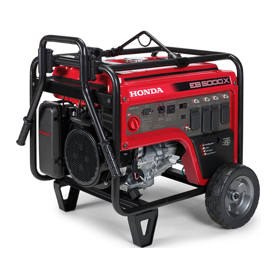
Honda EB5000X Owner's Manual
Honda generator
Hide thumbs
Also See for EB5000X:
- Owner's manual (112 pages) ,
- Information (28 pages) ,
- Owner's manual (71 pages)
Table of Contents
Advertisement
Quick Links
Advertisement
Table of Contents

Related Manuals for Honda EB5000X


Summary of Contents for Honda EB5000X
- Page 2 The generator is a potential source of electrical shock if misused. Do not expose the generator to moisture, rain or snow. Do not let the generator get wet, and do not operate it with wet hands.
- Page 3 Thank you for purchasing a Honda generator. We want to help you get the best results from your new generator and to operate it safely. This manual contains the information on how to do that; please read it carefully. This owner’s manual describes...
-
Page 4: Table Of Contents
CONTENTS SAFETY ..................4 Safety Label Locations . - Page 5 MAINTENANCE ................ Schedule ............Maintenance Tool Kit .................. Engine Oil Change ..............Air Cleaner Service..............Fuel Sediment Cup..............Spark Plug ................Spark Arrester Maintenance ..........TRANSPORTING/STORAGE ..........TROUBLESHOOTING .............. WIRING DIAGRAM ............................SPECIFICATIONS OF OPTIONAL PARTS ........INSTALLATION WARRANTY SERVICE ............
-
Page 6: Safety
SAFETY SAFETY LABEL LOCATION These labels warn you of potential hazards that can cause serious injury. Read them carefully. Ifalabelcomesofforbecc lmesha rdto read,contactyourHondaGenerator dealerfora replacement. GAS CONTAINS POISONOUS \ (WARNING DO NOT USE INDOORS.EXHAUST CARBON MONOXIDE. ATTENTION NE PAS”UTlllSER DANS UN ENDROIT FERME A CAUSE DU RISOUE D’EMPOISONNEMENT DU GAZ. - Page 7 IISING HONDA MOTOR CO.. . LTD. MADE IN JAPAN _-..-. CAUTION - - . . _ -. 12Oi24OV W BE SURE TO FILL CRANKCASE VOLTAGE 60Hz ;;WEJENCY WITH RECOMMENDED BEFORE -> OUTPUT TAILED EXPLANATION, iAX. OUTPUT PHASE : OWNER’S MANUAL.
-
Page 8: Safety Information
SAFETY INFORMATION Honda generators are designed to give safe and dependable service if operated according to instructions. Read and understand this owner’s manual before operating your generator. You can help prevent accidents by being familiar with your generator’s controls, and by observing safe operating... - Page 9 Fire and Burn Hazards The exhaust system gets hot enough to ignite some materials. Keep the generator at least 1 meter (3 feet) away from buildings and other equipment during operation. Do not enclose the generator in any structure. Keep flammable materials away from the generator. The muffler becomes very hot during operation and remains hot for a while after stopping the engine.
-
Page 10: Component Identification
COMPONENT IDENTIFICATION OIL ALERT LAMP VOLTAGE SELECTOR SWITCH ENGINE SWITCH RECEPTACLES UND TERMINAL OIL FILLER CAP AUTO THROTTLE AUTO THROTTLE SWITCH SWITCH OIL DRAIN PLUG ENGINE SERIAL NUMBER... - Page 11 FUEL TANK CAP FUEL METER SPARK PLUG OCCUPANT’ TEST RECORD MUFFLER FRAME SERIAL NUMBER Record the engine and frame serial numbers for your future reference. Refer to these serial numbers when ordering parts, and when making technical or warranty inquiries (see page 44) Frame serial number: Engine serial number:...
-
Page 12: Controls
CONTROLS Engine Switch To start and stop the engine. Switch position: OFF: To stop the engine. ON: To run the engine. ENGINE SWITCH Recoil Starter To start the engine, pull the starter grip lightly until resistance is felt, then pull briskly. -
Page 13: Fuel Valve
Fuel Valve The fuel valve is located between the fuel tank and carburetor. When the valve lever is in the ON position, fuel is allowed to flow from the fuel tank to the carburetor. Be sure to return the lever to OFF after stopping the engine. FUEL VALVE Choke Rod The choke is used to provide an enriched fuel mixture when starting a cold... -
Page 14: Voltage Selector Switch (Dual Voltage System)
Voltage Selector Switch (Dual Voltage System) The voltage selector switches the main power carrying windings of the generator to produce “12OV ONLY” or “120/24OV”. If a 240V appliance is connected to the 4-prong receptacle, the switch must be in the “120/24OV” position. -
Page 15: Oil Alert System
Oil Alert System The Oil Alert system is designed to prevent engine damage caused by an insufficient amount of oil in the crankcase. Before the oil level in the crankcase can fall below a safe limit, the Oil Alert system will automatically shut down the engine (the engine switch will remain in the ON position). -
Page 16: Circuit Breaker
Circuit Breaker The circuit breaker will automatically switch OFF if there is a short circuit or a significant overload of the generator at the receptacle. If the circuit breaker is switched OFF automatically, check that the appliance is working properly and does not exceed the rated load capacity of the circuit before switching the circuit breaker ON again. -
Page 17: Ground Fault Circuit Interrupter (Gfci)
Ground Fault Circuit Interrupter (GFCI) Receptacle Using the generator in rain, snow or near water can lead to death from electric shock. Keep the generator dry. All of the 20 ampere 120 volt receptacles on the generator are protected by a Ground Fault Circuit Interrupter (GFCI) for protection against the hazards of ground fault currents. - Page 18 3. Turn the circuit breaker ON. 4. Make sure the auto-throttle switch is OFF 5. Press the TEST BUTTON -The RESET BUTTON should extend with a click. the REST BUTTON does not extend, contact an authorized Honda generator dealer. TEST BUlTON...
- Page 19 -The RESET BUTTON should be flush with the test button. the RESET BUTTON is not flush with the TEST BUTTON, contact an authorized Honda generator dealer. 7. When the RESET BUTTON extends during operation: -Unplug all appliances from the GFCI protected receptacle.
-
Page 20: Generator Use
Ground System Honda portable generators have a system ground that connects generator frame components to the ground terminals in the AC output receptacles. The system ground is not connected to the AC neutral wire. If the generator is... -
Page 21: Ac Applications
AC Applications Before connecting an appliance or power cord to the generator: Make sure that it is in good working order. Faulty appliances or power cords can create a potential for electrical shock. If an appliance begins to operate abnormally, becomes sluggish or stops suddenly, turn it off immediately. -
Page 22: Ac Operation
AC Operation 1. Start the engine (refer to page 27). 2. Turn the voltage selector switch to either position. With the voltage selector switch in the “120/240V”position, you can use the 120V and 120/24OV receptacles simultaneously. If you are NOT using the 120/24OV receptacle, but require more power from the 12OV twist lock receptacle,... -
Page 23: Ac Receptacle Selection
AC Receptacle Selection The generator has two separate main power producing circuits. These two circuits supply equal power to different receptacles shown when the voltage selector switch is in the 120/240 V position. When two or more receptacles are used; prevent overloading by dividing the load between the two power circuits. -
Page 24: Auto-Throttle System
Auto-throttle system With the switch in the AUTO position, engine speed is automatically reduced when ALL loads are turned OFF or disconnected. When appliances turned ON or reconnected, the engine returns to rated speed. In the OFF position, the auto-throttle system does not operate. -
Page 25: High Altitude Operation
If you always operate the engine at altitudes higher than 6,000 feet above sea level, have an authorized Honda generator dealer perform this carburetor modification. Even with suitable carburetor... -
Page 26: Pre-Operation Check
2-stroke engine oils will damage the engine and are not recommended. Check the oil level BEFORE EACH USE with the generator on a level surface with the engine stopped. Honda 4-stroke oil, or an equivalent high detergent, premium quality motor oil certified to meet or U.S. -
Page 27: Fuel Recommendation
Fuel Recommendation 1. Check the fuel level gauge. 2. Refill the tank if the fuel level is low. Do not fill above the shoulder of the fuel strainer. Gasoline is extremely flammable and is explosive under certain conditions. Refuel in a well-ventilated area with the engine stopped. - Page 28 Honda and are not covered under warranty. 1 NOTICE 1 Oxygenated fuels can damage paint and plastic. careful not to spill fuel when filling your fuel tank. Damage caused by...
-
Page 29: Starting/Stopping The Engine
STARTING/STOPPING THE ENGINE Starting the engine 1. Make sure that the AC circuit breaker is in the OFF position. The generator may be hard to start if a load is connected. 2. Turn the fuel valve to the ON position. 3. -
Page 30: Maintenance
(Replace if necessary) (1) Service more frequently when used in dusty areas. (2) These items should be serviced by an authorized Honda generator dealer, unless the owner has the proper tools and is mechanically proficient. See the Honda Shop Manual. -
Page 31: Tool Kit
Tool kit The tools supplied with the generator will help you to perform the owner maintenance procedures listed on the following page. Always keep this tool kit with the generator. 10 x 12 mm WRENCH SCREW DRIVER PLUG WRENCH DRIVER HANDLE HANDLE BAR TOOL BAG... -
Page 32: Engine Oil Change
Engine oil change Drain the oil while the engine is warm to assure rapid and complete draining. 1. Remove the drain plug and sealing washer, oil filler cap, and drain the oil. 2. Reinstall the drain plug and sealing washer. Tighten the plug securely. 3. -
Page 33: Air Cleaner Service
Air cleaner service A dirty air cleaner will restrict air flow to the carburetor. To prevent carburetor malfunction, service the air cleaner regularly. Service more frequently when operating the generator in extremely dusty areas. Using gasoline or flammable solvent to clean the filter element can cause a fire or explosion. -
Page 34: Fuel Sediment Cup
Fuel Sediment Cup Cleaning The sediment cup prevents dirt or water which may be in the fuel tank from entering the carburetor. If the engine has not been run for a long time, the sediment cup should be cleaned. 1. Turn the fuel valve to the OFF position. Remove the sediment cup, O-ring, and filter. -
Page 35: Spark Plug
Spark Plug Service Recommended spark plugs: BPR5ES (NGK) Wl GEPR-U (NIPPONDENSO) To ensure proper engine operation, the spark plug must be properly gapped and free of deposits. If the engine has been running, the muffler will be very hot. Be careful not to touch the muffler. -
Page 36: Spark Arrester Maintenance
7. Check that the spark plug washer is in good condition, and thread the spark plug in by hand to prevent cross-threading. 8. After the spark plug is seated, tighten with a spark plug wrench to compress the washer. If installing a new spark plug, tighten l/2 turn after the spark plug seats to compress the washer. -
Page 37: Transporting/Storage
Change the engine oil. (Page 30). After removal from storage, drain the stored gasoline into a suitable container, and fill with fresh gasoline before starting. *Use gasoline conditioners that are formulated to extend storage life. Contact your authorized Honda generator dealer for conditioner recommendations. - Page 38 1. Drain the carburetor by loosening the drain screw. Drain the gasoline into a suitable container. Gasoline is extremely flammable and is explosive under certain conditions. Perform this task in a well ventilated area with the engine stopped. Do not smoke or allow flames or sparks in the area during this procedure.
-
Page 39: Troubleshooting
1) Turn off the engine switch DRAIN SCREW and loosen the drain screw. 2) Fuel should flow from the If the engine still drain when the engine does not start, take the generator to an switch is turned on. authorized Honda aenerator dealer. - Page 40 No electricity at the AC receptacles: Turn the AC circuit breaker ON. 1 YES Check the electrical NO DEFECTS appliance or equipment for any defects.
-
Page 41: Wiring Diagram
WIRING DIAGRAM... -
Page 42: Specifications
SPECIFICATIONS Dimensions Model EB5000X Power equipment description code 655 x 510 x 490 mm (25.8 x 20.1 x 19.3 in) Length x Width x Height 78 kg (172.0 lb) Dry weight Engine Model GX340Kl Engine type 4-stroke, overhead valve, single cylinder... -
Page 43: Installation Of Optional Parts
INSTALLATION OF OPTIONAL PARTS Hanger Kit Installation 1. Remove the upper frame. Install the hanger on it and install the upper frame on the body. BRACKET NOTE: Install at near center avoiding to install over the fuel filler cap. FUEL FILLER CAP... - Page 44 4-Wheel Kit Installation 1, Install the four wheels on the axle shaft. 2. Install the axle assembly on the generator using four bolts and nuts. Inside WHEEi STOPPER NOTE: Install the shaft with wheel stopper facing engine side.
- Page 45 2 Wheel kit Installation 1. Install the two wheels on the axle shaft. 2. Install the axle assembly on the generator using four bolts and nuts. 3. Install the two stands using four bolts and nuts. 4. Install right and left handles on the generator upper frame using brackets and six bolts.
-
Page 46: Warranty Service
Your purchase of a Honda product is greatly appreciated by both your dealer and American Honda Motor Co., Inc. We want to assist you in every way possible to assure your satisfaction with your purchase. - Page 47 When you write or call, please provide the following information: • Model and serial numbers • Name of the dealer who sold the Honda power equipment to you • Name and address of the dealer who services your equipment •...
-
Page 48: Index
INDEX ..........COMPONENT IDENTIFICATION ................CONTROLS System .............. Auto-throttle Choke Rod ................Circuit Breaker ............................Circuit Protector Engine Switch ..............Fuel Valve ................Ground Fault Circuit Interrupter (GFCI) ........ Ground Terminal ..............Oil Alert System ..............Recoil Starter ..............Voltage Selector Switch (Dual voltage System) .... - Page 49 INDEX PRE-OPERATION CHECK ............Engine Oil ............................Fuel Recommendation SAFETY ..................Safety Information ..............Safety Label Locations ............SPECIFICATIONS ..............STARTING/STOPPING THE ENGINE ..................TRANSPORTING/STORAGE TROUBLESHOOTING .............. WARRANTY SERVICE ............WIRING DIAGRAM ..............
- Page 50 MEMO...
- Page 51 MEMO...
Need help?
Do you have a question about the EB5000X and is the answer not in the manual?
Questions and answers