Table of Contents
Advertisement
Quick Links
Instruction Manual
760A/760D/760N
Stereo Audio Monitors
(760A S/N B050000 & Above)
(760D/760N S/N B030000 & Above)
070-5992-05
Warning
The servicing instructions are for use by qualified
personnel only. To avoid personal injury, do not
perform any servicing unless you are qualified to
do so. Refer to all safety summaries prior to
performing service.
Please check for change information
at the rear of this manual.
Advertisement
Table of Contents
Troubleshooting

Related Manuals for Tektronix 760A


Summary of Contents for Tektronix 760A
-
Page 1: Instruction Manual
Instruction Manual 760A/760D/760N Stereo Audio Monitors (760A S/N B050000 & Above) (760D/760N S/N B030000 & Above) 070-5992-05 Warning The servicing instructions are for use by qualified personnel only. To avoid personal injury, do not perform any servicing unless you are qualified to do so. - Page 2 Copyright Tektronix, Inc. All rights reserved. Tektronix products are covered by U.S. and foreign patents, issued and pending. Information in this publication supercedes that in all previously published material. Specifications and price change privileges reserved. Printed in the U.S.A. Tektronix, Inc., P.O. Box 1000, Wilsonville, OR 97070–1000...
- Page 3 Tektronix, with shipping charges prepaid. Tektronix shall pay for the return of the product to Customer if the shipment is to a location within the country in which the Tektronix service center is located.
-
Page 5: Table Of Contents
2–5 Using The 760A / 760D / 760N ........ - Page 6 ........6–6 760A / 760D / 760N...
- Page 7 ..........10–2 Cross Index–Mfr. Code Number to Manufacturer ......10–3 760A / 760D / 760N...
-
Page 8: List Of Figures
Contents List of Figures Figure 1–1: LED Bar Graph scales for the 760A, 760D, and 760N ..1–1 Figure 2–1: 760A Front Panel ........ -
Page 9: List Of Tables
....4–12 Table 5–1: Verifying Input Sensitivity (760A only) .... - Page 10 Contents 760A / 760D / 760N...
-
Page 11: General Safety Summary
CAUTION. Caution statements identify conditions or practices that could result in damage to this product or other property. Terms on the Product. These terms may appear on the product: 760A / 760D / 760N... - Page 12 CAUTION indicates a hazard to property including the product. Symbols on the Product. The following symbols may appear on the product: Double CAUTION WARNING Protective Ground Insulated (Earth) Terminal Refer to Manual High Voltage viii 760A / 760D / 760N...
-
Page 13: Service Safety Summary
To avoid electric shock, do not touch exposed connections. X-Radiation. To avoid x-radiation exposure, do not modify or otherwise alter the high-voltage circuitry or the CRT enclosure. X-ray emissions generated within this product have been sufficiently shielded. 760A / 760D / 760N... - Page 14 Service Safety Summary 760A / 760D / 760N...
-
Page 15: Preface
Preface This manual documents the TEKTRONIX 760A/760D/760N Stereo Audio Monitor and is intended for instrument operators and service technicians. Operatorsare assumed to be familiar with basic television terms and measure- ments. Qualified service technicians are also assumed to be familiar with television terms and measurements, and have moderate experience with analog and logic circuits. -
Page 16: Contacting Tektronix
For product support outside of North America, contact your local Tektronix distributor or sales office. Service Contact your local Tektronix distributor or sales office. Or visit Support our web site for a listing of worldwide service locations. http://www.tek.com For other... -
Page 17: Introduction And Specifications
Introduction and Specifications... -
Page 19: Section 1 Introduction And Specifications
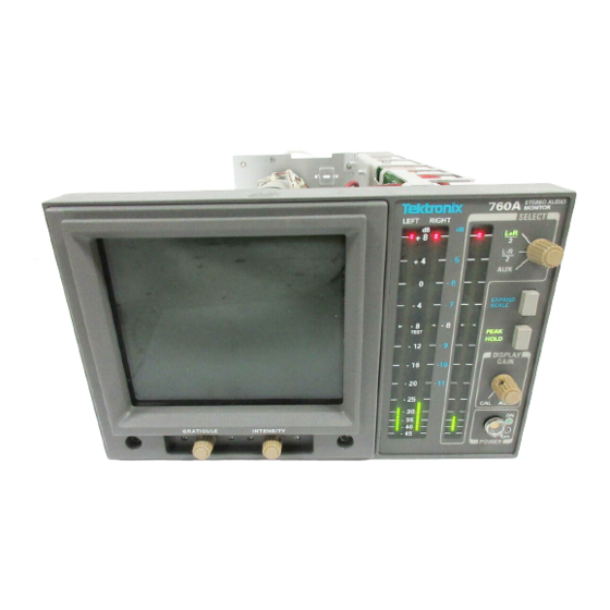
Introduction and Specifications Introduction The 760A Stereo Audio Monitor is a simple yet accurate tool that the audio engineer can use to perform setup, monitoring, measuring, and troubleshooting tasks in the studio. There are two special versions of the 760A Stereo Audio Monitor: the 760D and the 760N. -
Page 20: Bar Graph
Introduction and Specifications The display is set for a “Sound Stage” orientation when the 760A is shipped from the factory. This provides a display where monaural amplitudes are oriented on the vertical axis of the CRT. An alternate XY graticule is shipped as a standard accessory with the 760A. -
Page 21: Return Time
CSA –Electrical Bulletin No. 556B. IEC-348, Second Edition –Safety Standards For Electronic Measuring Apparatus. VDE 0871.5 (Class B) –Radio Frequency Interference Suppression of Electrical Equipment and Systems. FCC EMI Compatibility –FCC Rules Part 15 Subpart J, Class A. 1–3 760A / 760D / 760N... -
Page 22: Specifications
Specifications The Performance Requirements listed in Table 13 are warranted over an ambient temperature range of 0 C to 50 C only when the 760A has been calibrated at 25 C 5 C, following a warm–up period of 20 minutes. - Page 23 +8 to 20 dB +5 to 20 dB 760D +15 to 18 dB 760N Gain Match 0.3 dB. Crosstalk A full–scale indication on any bar SELECT set to AUX. causes no indication on any other bars. 1–5 760A / 760D / 760N...
-
Page 24: Table 1-4: Environmental Limits
Qualified under NTSB Test Procedure 1–A, Category II (30 inch drop). Table 1–5: Physical Characteristics Characteristic Supplemental Information Height 5.25 inches (13.3 cm). Width 8.424 inches (21.4 cm). Length 16.875 inches (42.9 cm). Weight Approximately 10 pounds. 1–6 760A / 760D / 760N... -
Page 25: Table 1-6: Certifications And Compliances
IEC 801-4 Electrical Fast Transient/Burst Immunity High-quality shielded cables must be used to ensure compliance to the above listed standards. This product complies when installed into any of the following Tektronix instrument enclosures: 1700F00 Standard Cabinet 1700F02 Portable Cabinet 1700F05 Rack Adapter... - Page 26 Introduction and Specifications 1–8 760A / 760D / 760N...
-
Page 27: Operating Instructions
Operating Instructions... -
Page 29: Section 2 Operating Instructions
Section 2 Operating Instructions Introduction This section of the manual will familiarize you with the 760A Stereo Audio Monitor’s operation. The contents include a brief description of the controls, connectors, displays (including a discussion of the graticules), and the basic uses of the instrument. -
Page 30: Rear-Panel Connectors
INTENSITY POSITION TRACE FOCUS VERT HORIZ Figure 2–1: 760A Front Panel Rear–Panel Connectors The three rear–panel AUDIO INPUTs: LEFT, RIGHT, and AUXILIARY, are balanced bridging male XLR connectors. The connectors are wired as follows: Pin 1: Ground Pin 2: + Pin 3: –... -
Page 31: Crt Display
760A CRT display. Display Orientation The 760A is shipped from the factory set for “Sound Stage” display orientation. This orientation provides a display where monaural amplitudes are displayed on the vertical axis, and stronger left content in the stereo signal would deflect the signal toward the left 45 axis (“L”... -
Page 32: Graticule
Figures 2–3 and 2–4 show the Sound Stage and XY graticules. AMPLITUDE MARKS PHASE MARKS L= –R PHASE TANGENT LINES Figure 2–3: 760A Sound Stage Graticule PHASE MARKS AMPLITUDE MARKS PHASE TANGENT LINES L= –R Figure 2–4: 760A X–Y Graticule 2–4... -
Page 33: Led Bars
LED bars, as described below: 760A The scale is dB linear between +8 and –20dB, with scale marks every 4 dB. Below –20 dB the scale is progressively tapered to –45 dB with marks every 5 dB. -
Page 34: Using The 760A / 760D / 760N
XY graticule. Initial Alignment 2. Connect power to the 760A / 760D / 760N and set the instrument POWER to ON. 3. With no input to the LEFT or RIGHT AUDIO INPUTs, set the front panel INTENSITY control fully clockwise. -
Page 35: Level Setups
Operating Instructions Level Setups 760A When a ppm such as the 760A is used in conjunction with vu meters. it is important to consider the difference in dynamic characteristics when aligning system levels. The vu meter is an average reading meter with a relatively long integration time. -
Page 36: Energy Distribution
Energy Distribution The 760A’s pattern display provides a graphic representation of the stereo signal’s overall energy distribution. The pattern orientation tells you at a glance whether the present mix is balanced or concentrated to either side. Figures 2–6 and 2–7 illustrate different energy distributions. -
Page 37: Monaural Compatibility
Polarity Reversal Routing audio through a complex studio presents many opportunities to introduce polarity reversals. Any time a polarity reversal occurs, the 760A can be used to trace the problem back to its source quickly. By introducing a sine 2–9... -
Page 38: Clipping
760A pattern display as a ”squaring off” of the pattern edges. Figure 2–9 illustrates a severe case of clipping. The 760A’s AGC keeps the pattern within the screen boundaries in spite of the amplitude of the signals Figure 2–9: Severe clipping of stereo signal... - Page 39 WARNING The following servicing instructions are for use only by qualified personnel. To avoid injury, do not perform any servicing other than that stated in the operating instructions unless you are qualified to do so. Refer to all Safety Summaries before performing any service.
-
Page 41: Section 3 Installation
Installation... -
Page 43: Electrical Installation
Changing Input Sensitivity The 760A is factory set so that a specific level applied to each input will indicate (Standard 760A only) a specific level on the bar graph scale (see Table 3–1). While this required input level may be changed for the standard 760A, the 760D and 760N are constrained to use only the factory set levels. -
Page 44: User-Definable Input Sensitivity (Standard 760A Only)
Installation To enable the 760A bar graph to indicate 0 dB with an input of 0, +4, +8, +12, or +16 dBm, move the jumpers on J185 (LEFT), J385 (RIGHT) and J657 (AUX- ILIARY) to the desired sensitivity, which is marked on the Main circuit board (Assembly A3) at each jumper location. -
Page 45: Figure 3-1: 760A / 760D / 760N Jumper Locations
JUMPERS 0 dB SENSITIVITY 4 dB JUMPERS 8 dB 12 dB ASSEMBLY A3 16 dB MAIN BOARD AUXILIARY INPUT Figure 3–1: 760A / 760D / 760N jumper locations for input and display orientation selections 3–3 760A / 760D / 760N... - Page 46 Installation 3–4 760A / 760D / 760N...
-
Page 47: Section 4 Maintenance
Maintenance... -
Page 49: Introduction
Abrasive cleaners should not be used. If the circuit board assemblies need cleaning, remove the circuit board by referring to the instruc- tions under Corrective Maintenance in this section. After cleaning, allow the interior to thoroughly dry before applying power to the instrument. 4–1 760A / 760D / 760N... -
Page 50: Visual Inspection
Foldout Pages. Figure 4–1 illustrates the foldout pages at the back of the manual which contain useful information for troubleshooting this instrument. Block and schematic diagrams, circuit board illustrations, and parts locating charts are located on the foldout pages. 4–2 760A / 760D / 760N... -
Page 51: Figure 4-1: Using The Foldout Pages
Theory of Operation. These pages can be turned to and read while the schematic diagram for that circuit description is folded out. 4–3 760A / 760D / 760N... -
Page 52: Figure 4-2: Circuit Board Locations In The 760A/760D/760N
BOARD A3 MAIN BOARD REAR PANEL Figure 4–2: Circuit board locations in the 760A/760D/760N The part numbers for ordering these boards are given in Section 8, Replaceable Electrical Parts. Generally, each component is assigned a circuit number according to its geographic location within an assembly. -
Page 53: Obtaining Replacement Parts
NOTE. The parts lists in this manual should be used when ordering replacement parts. Obtaining Replacement Replacement parts are available from or through the local Tektronix, Inc., field Parts office or representative. Changes to Tektronix instruments are sometimes made to accommodate improved components as they become available, and to give you the benefit of the latest circuit improvements developed in our Engineering Department. -
Page 54: Pal Signal Specification
GREATER goes low when DAC ramp is greater than the stored peak. PIN 8 (not used) PIN 12 GATE goes low to reset the peak value latch after the three–second timer has timed out. 4–6 760A / 760D / 760N... -
Page 55: Power Supply Troubleshooting Procedure
Apply AC power and turn on the power supply. From Table 4–1, determine which symptom the power supply exhibits and refer to the corresponding procedure. 4–7 760A / 760D / 760N... -
Page 56: Low Volts Supply
Power Supply by removing the jumper from J4. c. Use the digital multimeter to measure the voltage between TP2 and the tab (drain) of Q9. Be sure the voltage is near 0 V before proceeding. 4–8 760A / 760D / 760N... - Page 57 Connect the negative output from the 20 VDC Power Supply to TP2. Connect the positive output to the cathode of CR17. Short C47 with a clip lead. Connect the oscilloscope probe ground to TP2. 4–9 760A / 760D / 760N...
-
Page 58: High Volts Supply
If this check did not reveal the cause for the +5 V supply not regulating, refer to the Output Check and the Control Circuit Check. High Volts Supply Table 4–4 lists the High Volts Supply fault symptoms and procedures. 4–10 760A / 760D / 760N... -
Page 59: Table 4-4: High Volts Supply Fault Symptoms
Reconnect the lifted end of R8. Grid Drive Check Turn off the power supply. Use the digital multimeter’s diode check to test CR1, CR2, CR3, CR5, and CR6 for shorts. Turn on the power supply. 4–11 760A / 760D / 760N... -
Page 60: Table 4-5: High Voltage Oscillator Test Points
Use the high voltage probe to measure the voltage at the anode of CR4. It should be approximately –2530 V. Measure the voltage at the anode end of CR3. It should be 50-150 V more negative than the reading from the anode of CR4. 4–12 760A / 760D / 760N... -
Page 61: Mechanical Disassembly And Assembly
Maintenance MECHANICAL DISASSEMBLY AND ASSEMBLY Before removing parts from the 760A, disconnect the power cord and then remove the instrument from its cabinet. Reassembly is performed by reversing the steps used to disassemble the instrument. WARNING. For your protection and to avoid damage to the instrument, when removing or replacing any of the circuit boards, shut the instrument off. -
Page 62: Graticule Light Removal And Replacement
This should place the opening in the grommet on the front edge of the shield towards the bottom of the instrument. Ensure that the rubber manchet is on the back edge of the shield. 4–14 760A / 760D / 760N... -
Page 63: Rear Panel Removal And Replacement
2. Remove the two screws that hold the front–panel assembly in place. 3. The assembly can now be removed by slipping it through the front. 4. To access the Front Panel board components: a. Remove the two knobs from the front. 4–15 760A / 760D / 760N... -
Page 64: Led Bar And Socket Removal And Replacement
2. Push the trace rotation lead through its hole in the Main board. 3. Remove the knobs from the GRATICULE and ILLUMINATION controls. 4. Remove the eight retaining screws. See Figure 4–4 for locations. 4–16 760A / 760D / 760N... -
Page 65: Power Supply Board Removal And Replacement
4. Remove the two screws from the rear panel that hold the AC line filter in place. 5. Using a #1 Pozidrive tip, disconnect the power ON/OFF switch from the Front Panel assembly. 6. Remove the seven screws that are holding the board down. See Figure 4–4. 4–17 760A / 760D / 760N... -
Page 66: Repackaging
8. To replace the board, reverse this procedure. REPACKAGING If the instrument is to be shipped to a Tektronix Service Center for service or repair, attach a tag to the instrument showing: 1. Owner (with complete address) and the name of the person at your firm that can be contacted. - Page 67 3. Cushion the instrument on all sides by tightly packing dunnage or urethane foam between the carton and the instrument. Allow three inches on all sides for cushioning. 4. Seal the carton with shipping tape or an industrial stapler. 4–19 760A / 760D / 760N...
- Page 68 Maintenance 4–20 760A / 760D / 760N...
-
Page 69: Performance Check And Calibration
Performance Check and Calibration... -
Page 71: Section 5 Performance Check And Calibration Procedures
Introduction This section of the manual consists of two procedures. The Performance Check procedure is a guide to verifying warranted specifications of the 760A, while the Adjustment procedure, when properly performed, will result in a 760A that performs as warranted in SECTION 1, INTRODUCTION AND SPECIFICATION. -
Page 72: Performance Check Procedure
NOTE. This step must be performed prior to beginning this procedure. a. Set the 760A for a “Sound Stage” orientation (on A3 Main board, J273 and J373 to pins 2 and 3) and install the “Sound Stage” graticule, if your 760A is not set up in this way. - Page 73 Vary the autotransformer from low-line to high-line voltage (90 – 132 V for 110 V, or 180 – 250 V for 220 V operation). b. CHECK for stable instrument operation over the prescribed voltage – range. 5–3 760A / 760D / 760N...
- Page 74 Adjust the signal generator amplitude so that the bar graph’s top green LED is just lit. c. CHECK – that the signal generator amplitude is within the following limits: 760A: 748.7 – 802.1 mV (775 mV 0.3 dB) 760D: 531.4 – 569.3 mV (550 mV 0.3 dB)
-
Page 75: Table 5-1: Verifying Input Sensitivity (760A Only)
Performance Check and Calibration Procedures Check the RIGHT and AUXILIARY bars in the same manner, connect- ing the input signal to one 760A AUDIO INPUT at a time. (760A only) Set S340 to position 6. g. CHECK – (760A only) that each bar indicates 0 dB 0.3 dB (6... - Page 76 See Figure 2–3 for a description of the graticule. 8. Check Phase Match a. Set the 760A for an X–Y display orientation (P273 & P373 on pins 1 & 2, lower pins). Do not change to the X–Y graticule.
- Page 77 CHECK – that the trace extends to the major amplitude mark on the L graticule line. e. Connect inputs to all three AUDIO INPUTs. CHECK – that when the audio inputs are removed from the 760A, two segments at the top of the indicated levels remain lit for approximately three seconds.
- Page 78 Move the input from the RIGHT to the AUXILIARY AUDIO INPUT. CHECK – that with the EXPAND SCALE push button depressed, the AUXILIARY bar amplitude matches the LEFT bar amplitude within 0.3 dB. 5–8 760A / 760D / 760N...
- Page 79 (760D and 760N only) Reset the Input Termination, Sensitivity and Orientation jumpers to fit your application. Factory set positions are: Input Sensitivity: Input Termination: Display Orientation: Sound Stage See Figure 5–1 for jumper locations. 5–9 760A / 760D / 760N...
- Page 80 Orientation jumpers to fit your application. Factory set positions are: Input Sensitivity: 8 dB Input Termination: Display Orientation: Sound Stage See Figure 5–1 for jumper locations. This concludes the 760A / 760D / 760N Performance Check Procedure 5–10 760A / 760D / 760N...
-
Page 81: Calibration Procedure
Set the Input Termination (A3 – J192, J392, and J664) to Inf, and the Input Sensitivity (A3 – J185, J385, and J657) as shown: 760A 0 dB 760D, 760N b. Set the 760A front panel controls as follows: SELECT PEAK HOLD DISPLAY GAIN AUTO 2. Adjust +5 V a. -
Page 82: Figure 5-2: 760-Series Adjustment Locations
ADJUST – R58 (CRT BIAS) so that the display is just extinguished. d. Set the INTENSITY and GRATICULE controls to a desired level. e. Remove the signal at the LEFT AUDIO INPUT. 5–12 760A / 760D / 760N... - Page 83 NOTE. If the audio generator is capable of tone burst operation, such as the TEKTRONIX SG5010, it may be set for one second on one second off tone burst operation, instead of turning the generator on and off.
- Page 84 NOTE. If the audio generator is capable of tone burst operation, such as the TEKTRONIX SG5010, it may be set for one second on one second off tone burst operation, instead of turning the generator on and off.
-
Page 85: Table 5-2: Led Bar Gain Adjustment
R553 (Aux Offset Adjust) so that the correct number of LED segments are lighted, as shown in Table 5–2. d. (760A only) Set S340 to position 6 (expands around 0 dB, 0.05 dB/segment resolution). e. Set the audio signal generator to the output level shown in Table 5–3. - Page 86 Performance Check and Calibration Procedures 5–16 760A / 760D / 760N...
-
Page 87: Theory Of Operation
Theory of Operation... -
Page 89: Section 6 Theory Of Operation
Theory of Operation INTRODUCTION This section is intended to give a thorough understanding of the 760A / 760D / 760N Stereo Audio Monitor’s operational theory. A block diagram is provided to show the relationships between major functional blocks of circuitry. Each block directly relates to a portion of circuitry on a schematic that is described in detail in this section. -
Page 90: Matrix & Agc Control Logic <4
EXPAND Circles represent Front–Panel Controls SCALE Figure 6–1: 760A / 760D / 760N Block Diagram CRT Orthogonality Correction. A small amount of the signal from the horizontal signal path (amplitude and polarity adjusted by R463) is applied to the vertical path to correct for small differences in CRT deflection orthogonality. -
Page 91: Agc & Crt Deflection Amplifiers <5
–20dB to about +8 dB, for the standard 760A. This range changes to about –25 dB to +5 dB for the 760D, and about –15 dB to +15 dB for the 760N. The attack and decay capacitors allow for fast gain reduction on signal peaks, and for slow recovery to keep low frequency signals from “pumping”... -
Page 92: Graph Drivers <2
Comparator. U635B compares the rectified signal with the DAC ramp and (Left) provides the bar enabling signal. This signal is passed through logic contained in a PAL, U438, which is part of the Peak Hold circuit description that follows. 6–4 760A / 760D / 760N... -
Page 93: Bar Anode Driver (Left)
LED anodes low. Peak Hold On/Off The PEAK HOLD front–panel switch is debounced by an RC network and Schmitt gate U825A & B, which toggles flip–flop U823 for on/off control. 6–5 760A / 760D / 760N... -
Page 94: Bar Scanner/Driver & Dac <3
The Low Voltage Power Supply converts the mains line voltage (90–250 VAC) SUPPLY <6> to supply the power requirements of the instrument. The voltages supplied by the Low Voltage Power Supply are +40 V, 15 V, and +5 V. 6–6 760A / 760D / 760N... -
Page 95: Line Rectifier And Filter
U5 is a current-mode pulse width modulator (PWM). A current-mode PWM uses two feedback loops. The inner current feedback loop directly controls the switcher mosfet peak current. The outer voltage feedback loop programs the inner loop peak current trip point. 6–7 760A / 760D / 760N... -
Page 96: Output Filters
2.9 V. The output of comparator U3B will pull low and shut down pulse width modulator U5. C47 and R96 delay the operation of U3B long enough for the power supply to power up. If the +5 V does not reach 4.9 V 6–8 760A / 760D / 760N... -
Page 97: High Voltage Power Supply <7
C66 and Q10 are a Start Delay circuit that holds the Error Amplifier output low, through CR30, until C66 is charged. Delaying the start of the high voltage oscillator allows the Low Voltage Power Supply to start, unencumbered by the load from the high voltage oscillator. 6–9 760A / 760D / 760N... -
Page 98: Power Supply Outputs
Negative Z-Axis input current will cause the output to go positive. Q5 is a current amplifier feeding the output stage. Q3 and Q4 form a push-pull output stage. Q3 acts as a 2.7 mA constant current pull-up, while Q4 is the 6–10 760A / 760D / 760N... -
Page 99: Crt
Cathode (k) GRID (g1) FOCUS (g3) ASTIG (g4) GEOM (g5) VERT PLATE (y2) VERT PLATE (y1) HORIZ PLATE (x2) 1st ANODE (g2) HORIZ PLATE (x1) Filament (f) Figure 6–3: Pinout of the CRT Socket 6–11 760A / 760D / 760N... - Page 100 Theory of Operation 6–12 760A / 760D / 760N...
-
Page 101: Section 7 Options
Options... -
Page 103: Options
CSA certified. Option cords are approved by at least one test house acceptable in the country to which the product is shipped. Power cord types are illustrated on the exploded view in SECTION 10 REPLACEABLE MECHANICAL PARTS. 7–1 760A / 760D / 760N... - Page 104 Options 7–2 760A / 760D / 760N...
-
Page 105: Replaceable Electrical Parts
Replaceable Electrical Parts... -
Page 107: Parts Ordering Information
Section 8 Replaceable Electrical Parts This section contains a list of the electrical components for the 760A, 760D, and 760N. Use this list to identify and order replacement parts. Parts Ordering Information Replacement parts are available through your local Tektronix field office or representative. -
Page 108: Column Descriptions
Chassis-mounted parts have no assembly number prefix, and they are located at the end of the electrical parts list. Tektronix part number Use this part number when ordering replacement parts from Tektronix. 3 and 4 Serial number Column three indicates the serial number at which the part was first effective. Column four indicates the serial number at which the part was discontinued. - Page 109 C AND K COMPONENTS INC 15 RIVERDALE AVE NEWTON MA 02158–1057 1CH66 PHILIPS SEMICONDUCTORS 811 E ARQUES AVENUE SUNNYVALE CA 94088–3409 PO BOX 3409 1ES66 MAXIM INTEGRATED PRODUCTS INC 120 SAN GABRIEL DRIVE SUNNYVALE CA 94086 8–3 760A / 760D / 760N...
- Page 110 2200 LAKE PARK DR SMYRNA GA 30080 HEADQUARTERS AND GEORGIA OPERATIONS 53387 3M COMPANY 3M AUSTIN CENTER AUSTIN TX 78769–2963 ELECTRONIC PRODUCTS DIV 55680 NICHICON /AMERICA/ CORP 927 E STATE PKY SCHAUMBURG IL 60195–4526 8–4 760A / 760D / 760N...
- Page 111 DALE ELECTRONICS INC 2064 12TH AVE COLUMBUS NE 68601–3632 PO BOX 609 9M860 ESAM INC PO BOX 376 GRANTS PASS, OR 97526 TK2073 TOKYO COSMOS AMERICA INC 1177 E TOWER ROAD SCHAUMBURG, IL 60173 8–5 760A / 760D / 760N...
- Page 112 A1C17 285–1341–01 CAP,FXD,PLSTC:MTLZD FILM;0.1UF,20%,100V,POLYESTER TK1913 MKS 2 0.1UF 20% A1C18 281–0775–01 CAP,FXD,CERAMIC:MCL;0.1UF,20%,50V,Z5U,0.170 04222 SA105E104MAA A1C19 290–1310–00 CAP,FXD,ALUM:10UF,20%,160V,ESR=24.9 OHM 0H1N5 CEJSM2C100M (120HZ,20C),LS=0.200 INCH,13X20MM,105C,5000HRS A1C20 281–0707–00 CAP,FXD,CER DI:15000PF,10%,200V 04222 MA302C153KAA A1C21 281–0707–00 CAP,FXD,CER DI:15000PF,10%,200V 04222 MA302C153KAA 8–6 760A / 760D / 760N...
- Page 113 TK0515 PME 289 MB 5220 A1C57 285–1222–00 CAP,FXD,PLSTC:0.068UF,20%,250V TK0515 PME 271 M 568 A1C58 281–0809–00 CAP,FXD,CERAMIC:MLC;200 PF,5%,100V,0.100 X 0.170 04222 SA101A201JAA A1C59 281–0775–01 CAP,FXD,CERAMIC:MCL;0.1UF,20%,50V,Z5U,0.170 04222 SA105E104MAA A1C60 281–0775–01 CAP,FXD,CERAMIC:MCL;0.1UF,20%,50V,Z5U,0.170 04222 SA105E104MAA A1C61 281–0768–00 CAP,FXD,CER DI:470PF,20%,100V 04222 SA101A471KAA 8–7 760A / 760D / 760N...
- Page 114 LAMP,GLOW:135V MAX,1.9MA,C2A–T,WIRE LEAD 0J9R2 NE–2Q–11R–T A1F1 159–0021–00 FUSE,CARTRIDGE:3AG,2A,250V,FAST BLOW 71400 AGC–2 *MOUNTING PARTS* 200–2264–00 CAP,FUSEHOLDER:3AG FUSES 61935 FEK 031 1666 204–0906–00 BODY,FUSEHOLDER:3AG & 5 X 20MM FUSES 61935 TYPE FAU 031.35 *END MOUNTING PARTS* 8–8 760A / 760D / 760N...
- Page 115 A1R4 303–0155–00 RES,FXD,CMPSN:1.5M OHM,5%,1W 50139 GB1555 A1R5 303–0155–00 RES,FXD,CMPSN:1.5M OHM,5%,1W 50139 GB1555 A1R7 322–3385–00 RES,FXD:METAL FILM;100K OHM,1%,0.2W,TC=100 PPM 91637 CCF501G10002F A1R8 322–3097–00 RES,FXD:METAL FILM;100 OHM,1%,0.2W,TC=100 PPM 91637 CCF501G100R0F A1R11 311–1256–00 RES,VAR,TRMR:CERMET;2.5M OHM,10%,0.5W,0.375 32997 3386F–1–255 8–9 760A / 760D / 760N...
-
Page 116: Section 8 Replaceable Electrical Parts
91637 CCF501G49900F A1R55 322–3322–00 RES,FXD:METAL FILM;22.1K OHM,1%,0.2W,TC=100 91637 CCF501G22101F A1R56 322–3001–00 RES,FXD:METAL FILM;10 OHM,1%,0.2W,TC=100 PPM 91637 CCF501G10R00F A1R57 322–3034–00 RES,FXD:METAL FILM;22.1 OHM,1%,0.2W,TC=100 PPM 91637 CCF50–2–G22R10F A1R58 311–2239–00 RES,VAR,TRMR:CERMET;100K OHM,20%,0.5W,0.197 TK2073 GF06UT2 104 M L 8–10 760A / 760D / 760N... - Page 117 RES,FXD:METAL FILM;150K OHM,1%,0.2W,TC=100 PPM 91637 CCF50G15002F A1R95 322–3256–00 RES,FXD,FILM:4.53K OHM,1%,0.2W,TC=T0MI,SMALL BODY 91637 CCF50–2–G4531FT A1R96 322–3356–00 RES,FXD,FILM:49.9K OHM,1%,0.2W,TC=T0MI,SMALL BODY 91637 CCF501G49901F A1R97 322–3222–00 RES,FXD:METAL FILM;2K OHM,1%,0.2W,TC=100 PPM 91637 CCF501G20000F A1R98 322–3289–07 RES,FXD,FILM:10K OHM,0.1%,0.2W,TC=T9,T&R,SM BODY 91637 CCF501C10001B 8–11 760A / 760D / 760N...
- Page 118 DIODE,OPTO:LED;RED,626NM,101 ELEMENTLINEAR 50434 QDSP–8838 A2DS315 131–5251–00 CONN,BOX:PCB;FEMALE,STR,1 X 37,0.1CTR,0.350 H X 0.125 00779 3–534237–5 TAIL,30 GOLD A2DS412 150–1291–00 LED ASSEMBLY:DIRECTIONAL;3 IN 5 GREEN TK1155 150–1291–00 A2DS416 ––––––––––– (PART OF A2DS412) A2DS418 ––––––––––– (PART OF A2DS412) 8–12 760A / 760D / 760N...
- Page 119 CIRCUIT BD ASSY:MAIN 80009 671147205 (760N ONLY) *ATTACHED PARTS* 358–0723–00 STRAIN RLF,CA:1.9 L X 0.24 W X 0.56 HIGH,PLASTIC 53387 3448–3034 *END ATTACHED PARTS* A3C125 281–0775–00 CAP,FXD,CERAMIC:MLC;0.1UF,20%,50V,Z5U,0.170 04222 SA105E104MAA A3C127 281–0775–00 CAP,FXD,CERAMIC:MLC;0.1UF,20%,50V,Z5U,0.170 04222 SA105E104MAA 8–13 760A / 760D / 760N...
- Page 120 04222 SA105E104MAA A3C343 281–0775–00 CAP,FXD,CERAMIC:MLC;0.1UF,20%,50V,Z5U,0.170 04222 SA105E104MAA A3C344 281–0775–00 CAP,FXD,CERAMIC:MLC;0.1UF,20%,50V,Z5U,0.170 04222 SA105E104MAA A3C349 290–0990–01 CAP,FXD,ELCTLT:10UF,20%,50VTAPE & REEL 62643 511D296 A3C361 281–0775–00 CAP,FXD,CERAMIC:MLC;0.1UF,20%,50V,Z5U,0.170 04222 SA105E104MAA A3C368 281–0775–00 CAP,FXD,CERAMIC:MLC;0.1UF,20%,50V,Z5U,0.170 04222 SA105E104MAA A3C369 283–0164–00 CAP,FXD,CERAMIC:MLC;2.2UF,20%,25V,Z5U,0.40X 04222 SR403E225MAA 8–14 760A / 760D / 760N...
- Page 121 84411 TEK34–1049R5 (760A ONLY) A3C548 290–0990–01 CAP,FXD,ELCTLT:10UF,20%,50VTAPE & REEL 62643 511D296 A3C548 290–1313–00 CAP,FXD,ALUM:10UF,20%,50V,8 X 11MM;105 DEG,RDL,T&A 55680 UET1H100MPH1TA A3C554 281–0775–00 CAP,FXD,CERAMIC:MLC;0.1UF,20%,50V,Z5U,0.170 04222 SA105E104MAA A3C556 290–0974–03 CAP,FXD,ELCTLT:10UF,20%,60VDC 55680 UVX1H100MAA1TD A3C557 290–0974–03 CAP,FXD,ELCTLT:10UF,20%,60VDC 55680 UVX1H100MAA1TD 8–15 760A / 760D / 760N...
- Page 122 A3C735 281–0775–00 CAP,FXD,CERAMIC:MLC;0.1UF,20%,50V,Z5U,0.170 04222 SA105E104MAA A3C738 281–0775–00 CAP,FXD,CERAMIC:MLC;0.1UF,20%,50V,Z5U,0.170 04222 SA105E104MAA A3C744 281–0775–00 CAP,FXD,CERAMIC:MLC;0.1UF,20%,50V,Z5U,0.170 04222 SA105E104MAA A3C745 281–0775–00 CAP,FXD,CERAMIC:MLC;0.1UF,20%,50V,Z5U,0.170 04222 SA105E104MAA A3C746 281–0810–00 CAP,FXD,CERAMIC:MLC;5.6PF,+/–0.5PF,100V,0.100 X 0.170 04222 SA102A5R6DAA (760A ONLY) A3C748 281–0775–00 CAP,FXD,CERAMIC:MLC;0.1UF,20%,50V,Z5U,0.170 04222 SA105E104MAA 8–16 760A / 760D / 760N...
- Page 123 A3CR186 152–0141–02 DIODE,SIG:ULTRA FAST;40V,150MA,4NS,2PF 27014 FDH9427 A3CR187 152–0141–02 DIODE,SIG:ULTRA FAST;40V,150MA,4NS,2PF 27014 FDH9427 A3CR254 152–0066–00 DIODE,RECT:400V,1A,IFSM=30A,1.2VF,2US 0LUA3 1N5060 A3CR255 152–0066–00 DIODE,RECT:400V,1A,IFSM=30A,1.2VF,2US 0LUA3 1N5060 A3CR286 152–0141–02 DIODE,SIG:ULTRA FAST;40V,150MA,4NS,2PF 27014 FDH9427 A3CR287 152–0141–02 DIODE,SIG:ULTRA FAST;40V,150MA,4NS,2PF 27014 FDH9427 8–17 760A / 760D / 760N...
- Page 124 DIODE,SIG:ULTRA FAST;40V,150MA,4NS,2PF 27014 FDH9427 A3CR791 152–0141–02 DIODE,SIG:ULTRA FAST;40V,150MA,4NS,2PF 27014 FDH9427 A3CR846 152–0141–02 DIODE,SIG:ULTRA FAST;40V,150MA,4NS,2PF 27014 FDH9427 A3CR850 152–0141–02 DIODE,SIG:ULTRA FAST;40V,150MA,4NS,2PF 27014 FDH9427 A3CR851 152–0141–02 DIODE,SIG:ULTRA FAST;40V,150MA,4NS,2PF 27014 FDH9427 A3CR852 152–0141–02 DIODE,SIG:ULTRA FAST;40V,150MA,4NS,2PF 27014 FDH9427 8–18 760A / 760D / 760N...
- Page 125 MLG X 0.120 TAIL,30GOLD,BD RETENTION A3J668 131–4530–00 CONN,HDR:PCB;MALE,STR,1 X 3,0.1 CTR,0.230 00779 104344–1 MLG X 0.120 TAIL,30GOLD,BD RETENTION A3L513 108–1262–00 INDUCTOR,FXD:POWER;100UH,10%,I<0.75A,RDC<0.23 TK2058 TSL0807–101KR75 OHM,Q>15,SRF>5.4MHZ,BOBBIN CORE A3P185 131–3199–00 CONN,SHUNT:SHUNT;FEMALE,STR,1 X 2,0.1 CTR,0.2 H,LOW 22526 68786–202 PROFILE,JUMPER 8–19 760A / 760D / 760N...
- Page 126 TK2073 GF06UT2 102 M L20 ADJUST,T&R (760A ONLY) A3R155 311–2230–00 B030000 B030174 RES,VAR,TRMR:CERMET;500 OHM,20%,0.5W,0.197 TK2073 GF06UT2 501 M L SQ,TOP ADJUST (760D ONLY) A3R155 311–2231–00 B030175 RES,VAR,TRMR:CERMET,1K OHM,20%,0.5W,0.197 SQ,TOP TK2073 GF06UT2 102 M L20 ADJUST,T&R (760D ONLY) 8–20 760A / 760D / 760N...
- Page 127 RES,FXD,FILM:3K OHM,5%,0.25W TK1727 SFR25 2322–181– A3R274 322–3289–07 RES,FXD,FILM:10K OHM,0.1%,0.2W,TC=T9,T&R,SM BODY 91637 CCF501C10001B A3R275 322–3289–07 RES,FXD,FILM:10K OHM,0.1%,0.2W,TC=T9,T&R,SM BODY 91637 CCF501C10001B A3R276 322–3289–07 RES,FXD,FILM:10K OHM,0.1%,0.2W,TC=T9,T&R,SM BODY 91637 CCF501C10001B A3R277 322–3289–00 RES,FXD:METAL FILM;10K OHM,1%,0.2W,TC=100 PPM 91637 CCF50G10001F 8–21 760A / 760D / 760N...
- Page 128 RES,FXD,FILM:10K OHM,0.1%,0.2W,TC=T9,T&R,SM BODY 91637 CCF501C10001B A3R380 322–3373–00 RES,FXD,FILM:75K OHM,1%,0.2W,TC=T0MI,SMALL BODY 91637 CCF501G75001F A3R381 321–0748–06 RES,FXD,FILM:4.95K OHM,0.25%,0.125W,TC=T9 19701 5033RE4K950C A3R382 322–3237–00 RES,FXD,FILM:2.87K OHM,1%,0.2W,TC=T0MI,SMALL BODY 91637 CCF501G28700F A3R383 322–3373–00 RES,FXD,FILM:75K OHM,1%,0.2W,TC=T0MI,SMALL BODY 91637 CCF501G75001F (760A ONLY) 8–22 760A / 760D / 760N...
- Page 129 CMF65116G604ROF A3R520 311–2212–01 RES,VAR,NONWW:CKT BD,20K OHM,10%,0.25WLINEAR 12697 CM45228 A3R520 366–1701–01 KNOB:GY,0.127 ID X 0.392 OD X 0.4 H 80009 366170101 A3R541 321–0418–00 RES,FXD,FILM:221K OHM,1%,0.125W,TC=T0MI 19701 5043ED221K0F A3R543 322–3289–00 RES,FXD:METAL FILM;10K OHM,1%,0.2W,TC=100 PPM 91637 CCF50G10001F 8–23 760A / 760D / 760N...
- Page 130 A3R593 322–3385–00 RES,FXD:METAL FILM;100K OHM,1%,0.2W,TC=100 PPM 91637 CCF501G10002F A3R594 322–3193–00 RES,FXD:METAL FILM;1K OHM,1%,0.2W,TC=100 PPM 91637 CCF501G10000F A3R600 311–2269–00 RES,VAR,NONWW:TRMR,20K OHM,20%,0.5WLINEAR,MI TK2073 GF06VT2 203 M L A3R601 311–2269–00 RES,VAR,NONWW:TRMR,20K OHM,20%,0.5WLINEAR,MI TK2073 GF06VT2 203 M L 8–24 760A / 760D / 760N...
- Page 131 CCF501G10000F A3R675 322–3385–00 RES,FXD:METAL FILM;100K OHM,1%,0.2W,TC=100 PPM 91637 CCF501G10002F A3R676 321–0340–00 RES,FXD,FILM:34.0K OHM,1%,0.125W,TC=T0MI TK1727 2322–151–34K0 A3R677 322–3450–00 RES,FXD,FILM:475K OHM,1%,0.2W,TC=T0MI,SMALL 91637 CCF50–2G47502F A3R678 322–3481–00 RES,FXD,FILM:1M OHM.1%,0.2W,TC=T0MI,SMALL BODY 91637 CCF501G10003F A3R682 321–0340–00 RES,FXD,FILM:34.0K OHM,1%,0.125W,TC=T0MI TK1727 2322–151–34K0 8–25 760A / 760D / 760N...
- Page 132 RES,FXD,FILM:604 OHM,1%,0.5W,TC=T0 91637 CMF65116G604ROF A3R767 322–3289–00 RES,FXD:METAL FILM;10K OHM,1%,0.2W,TC=100 PPM 91637 CCF50G10001F A3R769 322–3354–00 RES,FXD:METAL FILM;47.5K OHM,1%,0.2W,TC=100 91637 CCF501G47501F A3R770 322–3222–00 RES,FXD:METAL FILM;2K OHM,1%,0.2W,TC=100 PPM 91637 CCF501G20000F A3R771 322–3193–00 RES,FXD:METAL FILM;1K OHM,1%,0.2W,TC=100 PPM 91637 CCF501G10000F 8–26 760A / 760D / 760N...
- Page 133 91637 CCF50G10001F A3R851 322–3289–00 RES,FXD:METAL FILM;10K OHM,1%,0.2W,TC=100 PPM 91637 CCF50G10001F A3R852 322–3289–00 RES,FXD:METAL FILM;10K OHM,1%,0.2W,TC=100 PPM 91637 CCF50G10001F A3R853 322–3314–00 RES,FXD:METAL FILM;18.2K OHM,1%,0.2W,TC=100 91637 CCF501G18201F (760A ONLY) A3R854 322–3258–00 RES,FXD:METAL FILM;4.75K OHM,1%,0.2W,TC=100 56845 CCF50–2–G4751FT 8–27 760A / 760D / 760N...
- Page 134 CB,0.015 X 0.032 BRASS,W/RED NYLON COLLAR A3TP552 214–4085–00 TERM,TEST POINT:0.070 ID,0.220 H,0.063 DIAP 26364 104–01–02 CB,0.015 X 0.032 BRASS,W/RED NYLON COLLAR A3TP554 214–4085–00 TERM,TEST POINT:0.070 ID,0.220 H,0.063 DIAP 26364 104–01–02 CB,0.015 X 0.032 BRASS,W/RED NYLON COLLAR 8–28 760A / 760D / 760N...
- Page 135 SN74LS138N A3U161 156–0480–02 IC,DIGITAL:LSTTL,GATES 01295 SN74LS08N A3U167 156–0858–00 IC,MISC:CMOS,ANALOG SWITCH;QUAD SPST 1ES66 DG201ACJ/C30248 A3U172 156–0858–00 IC,MISC:CMOS,ANALOG SWITCH;QUAD SPST 1ES66 DG201ACJ/C30248 A3U179 156–2817–00 IC,LINEAR:BIFET,OP–AMP;QUAD 04713 MC34084P A3U208 156–2818–00 IC,LINEAR:TTL,DRVR;8–CHAN SCE DRVR, LOW VOUT(SAT) 0CVK3 UDN2585A 8–29 760A / 760D / 760N...
- Page 136 A3U635 156–2901–00 IC,LINEAR:BIPOLAR,COMPARATOR;DUAL,10US,LOW 64155 LT1018CN8 OFFSET,LOW POWER A3U638 160–4234–00 IC,DIGITAL:STTL,PLD;PAL,16R6,28.5MHZ,180MA 80009 160423400 *MOUNTING PARTS* 136–0752–00 SOCKET,DIP:PCB;FEMALE,STR,2 X 10,0.3 CTR,0.210 H X 0.128 00779 2–641602–3 TAIL,TIN,PHOS BRONZE *END MOUNTING PARTS* A3U645 156–2817–00 IC,LINEAR:BIFET,OP–AMP;QUAD 04713 MC34084P 8–30 760A / 760D / 760N...
- Page 137 131–5338–00 CONN,HDR:PCB/WIREWRAP,;MALE,STR,1 X 7,0.15 CTR 22526 65561–107 A10SKT1 136–1289–00 SOCKET:CRT,TUBE;1730,SAFETY CONTROLLED 0LUA3 55595 J100 131–3208–00 CONN,CIRC:XLR,FEMALE,3 POS,SAFTEY CONTROLLED 82389 *MOUNTING PARTS* 211–0097–00 SCREW,MACHINE:4–40 X 0.312,PNH,STL TK0435 ORDER BY DESC (QUANTITY 2) *END MOUNTING PARTS* 8–31 760A / 760D / 760N...
- Page 138 WIRE HARNESS:DESCRETE,CRT ASSY,CPD,5,24 AWG,5,26 80009 179299700 AWG,1X4,0.1CTR & 1X7,RCPT X 1X4 & 1X7,0.1 RC 174–3511–00 CA ASSY,SP:DESCRETE,CPD,4,26 AWG,8.0L,1X7,0.1CTR,RCPT 9M860 174–3511–00 X STRAIN RELIEF,PCB *ATTACHED PARTS* – 344–0111–00 INSUL,SPREADER:DEFL LEADS,POLYPROPYLENE TK1617 NA *END ATTACHED PARTS* 8–32 760A / 760D / 760N...
- Page 139 Diagrams/Circuit Board Illustrations...
-
Page 141: Section 9 Diagrams/Circuit Board Illustrations
Example: ID CONTROL, (ID CONTROL), or /ID CONTROL. Abbreviations are based on ANSI Y1.1–1972. Other ANSI standards that are used in the preparation of diagrams by Tektronix, Inc. are: Y14.15, 1966 — Drafting Practices. Y14.2, 1973 — Line Conventions and Lettering. - Page 142 When more than one schematic diagram is used to illustrate the circuitry on a circuit board, the circuit board illustration will only appear opposite the first diagram; the lookup table will list the diagram number of other diagrams that the other circuitry appears on. 9–2 760A / 760D / 760N...
- Page 143 A3 Main Board Diagram Component Locator C125 C502 CR565 Q769 R344 R520 R673 R784 U462C C127 C510 C755 CR566 Q776 R347 R541 R674 TP552 U462D C132 C523 C758 CR616 Q795 R351 R675 R785 TP554 U468 C145 C764 CR638 R543 R676 R786 TP568 U590...
- Page 144 C254 C332 C415 C527 C612 C744 C874 CR456 J198 R177 R387 R488 U179B C255 C333 C436 C530 C646 C745 C880 J385 R180 R280 R388 R495 R661 TP151 U179C C258 C445 C660 C881 CR486 J386 R181 760A / 760D / 760N...
- Page 145 LEFT INPUT AMPLIFIER VOLTAGE REGULATORS AND DECOUPLING RIGHT INPUT AMPLIFIER INPUT AMPLIFIER 760A/760D/760N STEREO AUDIO MONITOR INPUT AMPLIFIERS AND DECOUPLING...
- Page 146 R451 U708A CR638 R541 TP551 U708B CR642 TP552 U708C CR643 R543 U708D R546 U208 CR742 R547 U213 U823A CR743 R548 U223 U823B CR746 R550 U308 U825A CR747 U313 U825B R551 J115 R605 U428 R617 U432 760A / 760D / 760N...
- Page 147 LEFT BAR ANODE DRIVER LEFT DYNAMIC RESPONSE CONTROL (PPM) LEFT SIGNAL PEAK PROCESSOR PEAK HOLD ON/OFF RIGHT SIGNAL PEAK PROCESSOR RIGHT BAR ANODE DRIVER RIGHT DYNAMIC RESPONSE CONTROL (PPM) 760A/760D/760N STEREO AUDIO MONITOR GRAPH DRIVERS...
- Page 148 U838B CR850 R758 U137 U844A CR851 R815 U142 U844B CR852 R842 U146 U848 R843 U853A CR853 U217 CR854 R844 U317 U853B CR855 R845 U424 U853C R846 U453D U853D R247 R849 U623 R248 R851 U711A R252 760A / 760D / 760N...
- Page 149 AUX SIGNAL PEAK PROCESSOR AUX BAR ANODE DRIVER AUX DYNAMIC RESPONSE CONTROL (PPM) MASTER CLOCK SCALE SHAPER/ LOOK–UP TABLE DOWN COUNTER 760A/760D/760N STEREO AUDIO MONITOR BAR SCANNER / DRIVER AND DAC...
- Page 150 CR564 R469 U361 CR565 R264 U368 CR566 R265 R470 U379A R358 R472 U462A J273 R359 R474 J373 R362 R558 U462B J413 R560 U462C J419 R363 U462D R364 R562 U468 Q603 R366 R563 Q604 R370 R564 760A / 760D / 760N...
- Page 151 45 DEGREE ORTHOGONALITY MATRIX CORRECTION AUX BAR SELECT GAIN CONTROL LOGIC TRACE ROTATION 760A/760D/760N STEREO AUDIO MONITOR MATRIX AND AGC CONTROL LOGIC...
- Page 152 R783 U680B CR876 R613 R784 R785 U873A J409 R615 R786 U873B J862 R672 U880A J886 R673 R787 U880B R674 R788 U894A L513 R675 R789 R790 U894B Q620 R676 R794 Q695 R677 Q761 R678 R797 Q766 760A / 760D / 760N...
- Page 153 VERTICAL OUTPUT AMPLIFIER LOW PASS FILTER VERTICAL GAIN CONTROL GRATICULE ILLUMINATION Z–AXIS DIMMING HORIZONTAL GAIN CONTROL HORIZONTAL OUTPUT AMPLIFIER LOW PASS FILTER 760A/760D/760N STEREO AUDIO MONITOR AGC AND CRT DEFLECTION AMPS...
- Page 154 See Maintenance Section A1 Board and Diagram <6> Component Locator CR11 R103 CR12 FIL1 CR13 FIL2 CR14 CR15 CR16 CR17 CR18 CR19 CR20 CR21 CR22 CR23 CR24 CR25 CR26 CR27 CR29 CR30 CR31 R101 CR10 R102 760A / 760D / 760N...
- Page 155 LINE RECTIFIER AND FILTER OUTPUT FILTERS CLAMP OUTPUT UV SHUTDOWN PULSE WIDTH MODULATOR SWITCHER SNUBBER MOSFET CROWBAR ERROR FEEDBACK AMPLIFIER TRANSFORMER DRIVER PEAK DETECTOR 760A/760D/760N STEREO AUDIO MONITOR LOW VOLTS POWER SUPPLY...
- Page 156 Assembly A1. Partial Assembly A1 also shown on Schematic 6. CR31 FIL1 FIL2 A10 CRT Socket Board (Front of Board) R103 CR30 A10 CRT Socket Board (Back of Board) 760A / 760D / 760N...
- Page 157 HV OSC & ERROR AMP GRID DRIVE Z AXIS AMPLIFIER FOCUS AMPLIFIER V1 TUBE SOCKET VISUAL AID 760A/760D/760N STEREO AUDIO MONITOR HIGH VOLTS POWER SUPPLY...
- Page 158 See Maintenance Section Schematic Diagram <8> Component Locator Chart Assembly A2. C355 R437 R438 DS115 R439 DS215 R451 DS315 DS412 S516 DS416 S525 DS418 S534 DS432 S544A DS434 S544B J110 U320 J135 U332 U347 R423 R424 R425 760A / 760D / 760N...
- Page 159 760A/760D/760N STEREO AUDIO MONITOR FRONT PANEL...
- Page 161 Replaceable Mechanical Parts...
-
Page 163: Section 10 Replaceable Mechanical Parts
Replaceable Mechanical Parts This section contains a list of the replaceable mechanical components for the 760A, 760D, and 760N. Use this list to identify and order replacement parts. Parts Ordering Information Replacement parts are available through your local Tektronix field office or representative. -
Page 164: Column Descriptions
Items in this section are referenced by figure and index numbers to the exploded view illustrations that follow. Tektronix part number Use this part number when ordering replacement parts from Tektronix. 3 and 4 Serial number Column three indicates the serial number at which the part was first effective. Column four indicates the serial number at which the part was discontinued. - Page 165 80126 PACIFIC ELECTRICORD CO 747 W REDONDO BEACH GARDENA CA 90247–4203 PO BOX 10 85471 BOYD CORP 13885 RAMOMA AVE CHINO CA 91710 93907 TEXTRON INC 600 18TH AVE ROCKFORD IL 61108–5181 CAMCAR DIV 10–3 760A / 760D / 760N...
- Page 166 SCREW,MACH:6–32 X 0.375,PNH,STL,CDPL,T–15 TORX DR 0KB01 ORDER BY DESC (760A ONLY) 211–0721–00 B030000 B030174 SCREW,MACH:6–32 X 0.375,PNH,STL,CDPL,T–15 TORX DR 0KB01 ORDER BY DESC (760D ONLY) 211–0721–00 B030175 SCREW,MACH:6–32 X 0.375,PNH,STL,CDPL,T–15 TORX DR 0KB01 ORDER BY DESC (760D ONLY) 10–4 760A / 760D / 760N...
- Page 167 SCALE,CRT:X–Y GRATICULE,760 0JR05 331–0496–00 070–5992–05 MANUAL,TECH:INST,760A,760D,760N 80009 070599203 150–1181–00 DIODE,OPTO:LED;RED,626NM,101 ELEMENTLINEAR 50434 QDSP–8838 ARRAY,0.100” SIP,COM–CATH –43 161–0216–00 CABLE ASSY,PWR,:3,18 AWG,2.5M L,BLACK 80126 C7120–25M–BL –44 161–0215–00 CABLE ASSY,PWR:3,0.75MU,2.5MM L,GREY 80126 0–5335–008–GY (EUROPEAN OPTION A1 ONLY) 10–5 760A / 760D / 760N...
- Page 168 –49 211–0720–01 B052743 SCREW,MACH:6–32 X 0.50,PNH,STL,TORX T–15WITH 0KB01 211–0720–01 SLOT (760A ONLY) 211–0720–01 B030175 SCREW,MACH:6–32 X 0.50,PNH,STL,TORX T–15WITH 0KB01 211–0720–01 SLOT (760D ONLY) 211–0720–01 B030209 SCREW,MACH:6–32 X 0.50,PNH,STL,TORX T–15WITH 0KB01 211–0720–01 SLOT (760N ONLY) 10–6 760A / 760D / 760N...
- Page 169 760A/760D/760N...
Need help?
Do you have a question about the 760A and is the answer not in the manual?
Questions and answers