
Related Manuals for Tektronix 760A


Summary of Contents for Tektronix 760A
- Page 1 760A/760D/760N Stereo Audio Monitors (760A SN B040000 & Above) (760D/760N SN B020000 & Above) Instruction Manual *P070599203* 070-5992-03...
- Page 3 Instruction Manual 760A/760D/760N Stereo Audio Monitors (760A S/N B040000 & Above) (760D/760N S/N B020000 & Above) 070-5992-03 Warning The servicing instructions are for use by qualified personnel only. To avoid personal injury, do not perform any servicing unless you are qualified to do so.
- Page 4 Copyright Tektronix, Inc., 1986, 1992, 1995. All rights reserved. Printed in U.S.A. Tektronix products are covered by U.S. and foreign patents, issued and pending. Information in this publication supersedes that in all previously published material. Specifications and price change privileges reserved. The following are registered trademarks: TEKTRONIX and TEK.
- Page 5 Tektronix, with shipping charges prepaid. Tektronix shall pay for the return of the product to Customer if the shipment is to a location within the country in which the Tektronix service center is located.
- Page 7 German Postal Information Certificate of the Manufacturer/Importer We hereby certify that the 760A / 760D / 760N and all factory installed options complies with the RF Interference Suppression requirements of Postal Regulation Vfg. 243/1991, Amended per Vfg. 46/1992 The German Postal Service was notified that the equipment is being marketed.
-
Page 9: Table Of Contents
2–5 Using The 760A / 760D / 760N ........ - Page 10 ........6–6 760A / 760D / 760N...
- Page 11 ..........10–2 Cross Index–Mfr. Code Number to Manufacturer ......10–1 760A / 760D / 760N...
-
Page 12: List Of Figures
Contents List of Figures Figure 1–1: LED Bar Graph scales for the 760A, 760D, and 760N ..1–1 Figure 2–1: 760A Front Panel ........ -
Page 13: List Of Tables
....4–12 Table 5–1: Verifying Input Sensitivity (760A only) .... - Page 14 Contents 760A / 760D / 760N...
-
Page 15: General Safety Summary
Product Damage Precautions Provide Proper Ventilation To prevent product overheating, provide proper ventilation. Do Not Operate With If you suspect there is damage to this product, have it inspected by qualified Suspected Failures service personnel. 760A / 760D / 760N... - Page 16 Certifications and Compliances CSA Certified Power CSA Certification includes the products and power cords appropriate for use in Cords the North America power network. All other power cords supplied are approved for the country of use. viii 760A / 760D / 760N...
-
Page 17: Service Safety Summary
To avoid electric shock, do not touch exposed connections. X-Radiation To avoid x-radiation exposure, do not modify or otherwise alter the high-voltage circuitry or the CRT enclosure. X-ray emissions generated within this product have been sufficiently shielded. 760A / 760D / 760N... - Page 18 Service Safety Summary 760A / 760D / 760N...
-
Page 19: Preface
Preface This manual documents the TEKTRONIX 760A/760D/760N Stereo Audio Monitor and is intended for instrument operators and service technicians. Operatorsare assumed to be familiar with basic television terms and measure- ments. Qualified service technicians are also assumed to be familiar with television terms and measurements, and have moderate experience with analog and logic circuits. - Page 20 Section 10, replaceable Mechanical Parts List, includes ordering information and part numbers for all replaceable mechanical aprts. This parts list is referenced to an exploded view mechanical drawing. Also included are lists of standard and optional accessories. 760A / 760D / 760N...
-
Page 21: Introduction And Specifications
Introduction and Specifications... -
Page 23: Section 1 Introduction And Specifications
Introduction and Specifications Introduction The 760A Stereo Audio Monitor is a simple yet accurate tool that the audio engineer can use to perform setup, monitoring, measuring, and troubleshooting tasks in the studio. There are two special versions of the 760A Stereo Audio Monitor: the 760D and the 760N. -
Page 24: Bar Graph
Introduction and Specifications The display is set for a “Sound Stage” orientation when the 760A is shipped from the factory. This provides a display where monaural amplitudes are oriented on the vertical axis of the CRT. An alternate XY graticule is shipped as a standard accessory with the 760A. -
Page 25: Return Time
CSA –Electrical Bulletin No. 556B. IEC-348, Second Edition –Safety Standards For Electronic Measuring Apparatus. VDE 0871.5 (Class B) –Radio Frequency Interference Suppression of Electrical Equipment and Systems. FCC EMI Compatibility –FCC Rules Part 15 Subpart J, Class A. 1–3 760A / 760D / 760N... -
Page 26: Specifications
Specifications The Performance Requirements listed in Table 13 are warranted over an ambient temperature range of 0°C to 50°C only when the 760A has been calibrated at 25°C ±5°C, following a warm–up period of 20 minutes. A Performance Check procedure is provided in SECTION 5, PERFORMANCE CHECK AND CALIBRATION PROCEDURES, to verify the Performance Require- ments listed in the following table. - Page 27 +8 to 20 dB 760D +5 to 20 dB +15 to 18 dB 760N Gain Match 0.3 dB. Crosstalk A full–scale indication on any bar SELECT set to AUX. causes no indication on any other bars. 1–5 760A / 760D / 760N...
-
Page 28: Table 1-4: Environmental Limits
Qualified under NTSB Test Procedure 1–A, Category II (30 inch drop). Table 1–5: Physical Characteristics Characteristic Supplemental Information Height 5.25 inches (13.3 cm). Width 8.424 inches (21.4 cm). Length 16.875 inches (42.9 cm). Weight Approximately 10 pounds. 1–6 760A / 760D / 760N... -
Page 29: Operating Instructions
Operating Instructions... -
Page 31: Section 2 Operating Instructions
Section 2 Operating Instructions Introduction This section of the manual will familiarize you with the 760A Stereo Audio Monitor’s operation. The contents include a brief description of the controls, connectors, displays (including a discussion of the graticules), and the basic uses of the instrument. -
Page 32: Rear-Panel Connectors
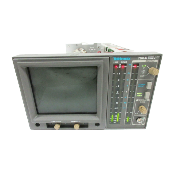
INTENSITY POSITION TRACE FOCUS VERT HORIZ Figure 2–1: 760A Front Panel Rear–Panel Connectors The three rear–panel AUDIO INPUTs: LEFT, RIGHT, and AUXILIARY, are balanced bridging male XLR connectors. The connectors are wired as follows: Pin 1: Ground Pin 2: + Pin 3: –... -
Page 33: Crt Display
760A CRT display. Display Orientation The 760A is shipped from the factory set for “Sound Stage” display orientation. This orientation provides a display where monaural amplitudes are displayed on the vertical axis, and stronger left content in the stereo signal would deflect the signal toward the left 45°... -
Page 34: Graticule
Figures 2–3 and 2–4 show the Sound Stage and XY graticules. AMPLITUDE MARKS PHASE MARKS L= –R PHASE TANGENT LINES Figure 2–3: 760A Sound Stage Graticule PHASE MARKS AMPLITUDE MARKS PHASE TANGENT LINES L= –R Figure 2–4: 760A X–Y Graticule 2–4... -
Page 35: Led Bars
LED bars, as described below: 760A The scale is dB linear between +8 and –20dB, with scale marks every 4 dB. Below –20 dB the scale is progressively tapered to –45 dB with marks every 5 dB. -
Page 36: Using The 760A / 760D / 760N
XY graticule. Initial Alignment 1. Connect power to the 760A / 760D / 760N and set the instrument POWER to ON. 2. With no input to the LEFT or RIGHT AUDIO INPUTs, set the front panel INTENSITY control fully clockwise. -
Page 37: Level Setups
Operating Instructions Level Setups 760A When a ppm such as the 760A is used in conjunction with vu meters. it is important to consider the difference in dynamic characteristics when aligning system levels. The vu meter is an average reading meter with a relatively long integration time. -
Page 38: Energy Distribution
Energy Distribution The 760A’s pattern display provides a graphic representation of the stereo signal’s overall energy distribution. The pattern orientation tells you at a glance whether the present mix is balanced or concentrated to either side. Figures 2–6 and 2–7 illustrate different energy distributions. -
Page 39: Monaural Compatibility
Polarity Reversal Routing audio through a complex studio presents many opportunities to introduce polarity reversals. Any time a polarity reversal occurs, the 760A can be used to trace the problem back to its source quickly. By introducing a sine 2–9... -
Page 40: Clipping
760A pattern display as a ”squaring off” of the pattern edges. Figure 2–9 illustrates a severe case of clipping. The 760A’s AGC keeps the pattern within the screen boundaries in spite of the amplitude of the signals Figure 2–9: Severe clipping of stereo signal... - Page 41 WARNING The following servicing instructions are for use only by qualified personnel. To avoid injury, do not perform any servicing other than that stated in the operating instructions unless you are qualified to do so. Refer to all Safety Summaries before performing any service.
-
Page 43: Section 3 Installation
Installation... -
Page 45: Electrical Installation
Changing Input Sensitivity The 760A is factory set so that a specific level applied to each input will indicate (Standard 760A only) a specific level on the bar graph scale (see Table 3–1). While this required input level may be changed for the standard 760A, the 760D and 760N are constrained to use only the factory set levels. -
Page 46: User-Definable Input Sensitivity (Standard 760A Only)
Installation To enable the 760A bar graph to indicate 0 dB with an input of 0, +4, +8, +12, or +16 dBm, move the jumpers on J185 (LEFT), J385 (RIGHT) and J657 (AUX- ILIARY) to the desired sensitivity, which is marked on the Main circuit board (Assembly A3) at each jumper location. -
Page 47: Figure 3-1: 760A / 760D / 760N Jumper Locations
JUMPERS 0 dB SENSITIVITY 4 dB JUMPERS 8 dB 12 dB ASSEMBLY A3 16 dB MAIN BOARD AUXILIARY INPUT Figure 3–1: 760A / 760D / 760N jumper locations for input and display orientation selections 3–3 760A / 760D / 760N... - Page 48 Installation 3–4 760A / 760D / 760N...
-
Page 49: Section 4 Maintenance
Maintenance... -
Page 51: Introduction
Abrasive cleaners should not be used. If the circuit board assemblies need cleaning, remove the circuit board by referring to the instruc- tions under Corrective Maintenance in this section. After cleaning, allow the interior to thoroughly dry before applying power to the instrument. 4–1 760A / 760D / 760N... -
Page 52: Visual Inspection
Foldout Pages. Figure 4–1 illustrates the foldout pages at the back of the manual which contain useful information for troubleshooting this instrument. Block and schematic diagrams, circuit board illustrations, and parts locating charts are located on the foldout pages. 4–2 760A / 760D / 760N... -
Page 53: Figure 4-1: Using The Foldout Pages
Theory of Operation. These pages can be turned to and read while the schematic diagram for that circuit description is folded out. 4–3 760A / 760D / 760N... -
Page 54: Figure 4-2: Circuit Board Locations In The 760A/760D/760N
BOARD A3 MAIN BOARD REAR PANEL Figure 4–2: Circuit board locations in the 760A/760D/760N The part numbers for ordering these boards are given in Section 8, Replaceable Electrical Parts. Generally, each component is assigned a circuit number according to its geographic location within an assembly. -
Page 55: Obtaining Replacement Parts
NOTE. The parts lists in this manual should be used when ordering replacement parts. Obtaining Replacement Replacement parts are available from or through the local Tektronix, Inc., field Parts office or representative. Changes to Tektronix instruments are sometimes made to accommodate improved components as they become available, and to give you the benefit of the latest circuit improvements developed in our Engineering Department. -
Page 56: Pal Signal Specification
GREATER goes low when DAC ramp is greater than the stored peak. PIN 8 (not used) PIN 12 GATE goes low to reset the peak value latch after the three–second timer has timed out. 4–6 760A / 760D / 760N... -
Page 57: Power Supply Troubleshooting Procedure
Apply AC power and turn on the power supply. From Table 4–1, determine which symptom the power supply exhibits and refer to the corresponding procedure. 4–7 760A / 760D / 760N... -
Page 58: Low Volts Supply
Power Supply by removing the jumper from J4. c. Use the digital multimeter to measure the voltage between TP2 and the tab (drain) of Q9. Be sure the voltage is near 0 V before proceeding. 4–8 760A / 760D / 760N... - Page 59 Connect the negative output from the 20 VDC Power Supply to TP2. Connect the positive output to the cathode of CR17. Short C47 with a clip lead. Connect the oscilloscope probe ground to TP2. 4–9 760A / 760D / 760N...
-
Page 60: High Volts Supply
If this check did not reveal the cause for the +5 V supply not regulating, refer to the Output Check and the Control Circuit Check. High Volts Supply Table 4–4 lists the High Volts Supply fault symptoms and procedures. 4–10 760A / 760D / 760N... -
Page 61: Table 4-4: High Volts Supply Fault Symptoms
H Reconnect the lifted end of R8. Grid Drive Check H Turn off the power supply. Use the digital multimeter’s diode check to test CR1, CR2, CR3, CR5, and CR6 for shorts. H Turn on the power supply. 4–11 760A / 760D / 760N... -
Page 62: Table 4-5: High Voltage Oscillator Test Points
H Use the high voltage probe to measure the voltage at the anode of CR4. It should be approximately –2750 V. H Measure the voltage at the anode end of CR3. It should be 50-150 V more negative than the reading from the anode of CR4. 4–12 760A / 760D / 760N... -
Page 63: Mechanical Disassembly And Assembly
Maintenance MECHANICAL DISASSEMBLY AND ASSEMBLY Before removing parts from the 760A, disconnect the power cord and then remove the instrument from its cabinet. Reassembly is performed by reversing the steps used to disassemble the instrument. WARNING. For your protection and to avoid damage to the instrument, when removing or replacing any of the circuit boards, shut the instrument off. -
Page 64: Graticule Light Removal And Replacement
CRT holder. 7. Slip the CRT part way back into position, so that the trace rotation wires can be fed back through the hole in the Main board. 4–14 760A / 760D / 760N... -
Page 65: Rear Panel Removal And Replacement
5. To reassemble, reverse the procedure. NOTE. When remounting the Front Panel board to the front panel, carefully line up the LED bars so they fit inside the cut–outs in the front panel. 4–15 760A / 760D / 760N... -
Page 66: Main Board Removal And Replacement
FRONT A3 Main board retaining screws Figure 4–4: Retaining screw locations 5. To remove the board, slide it toward the rear panel until the potentiometer shafts clear the front and then lift it out. 4–16 760A / 760D / 760N... -
Page 67: Power Supply Board Removal And Replacement
8. To replace the board, reverse this procedure. REPACKAGING If the instrument is to be shipped to a Tektronix Service Center for service or repair, attach a tag to the instrument showing: 1. Owner (with complete address) and the name of the person at your firm that can be contacted. -
Page 68: Figure 4-5: Repackaging The 760A/760D/760N
Ï Ï Ï Ï Ï Ï Ï Ï Ï Figure 4–5: Repackaging the 760A/760D/760N For best results, save and reuse the package in which your instrument was shipped. If the original package is unfit for use or not available, repackage the instrument as follows: 1. -
Page 69: Performance Check And Calibration
Performance Check and Calibration... -
Page 71: Section 5 Performance Check And Calibration Procedures
Introduction This section of the manual consists of two procedures. The Performance Check procedure is a guide to verifying warranted specifications of the 760A, while the Adjustment procedure, when properly performed, will result in a 760A that performs as warranted in SECTION 1, INTRODUCTION AND SPECIFICATION. -
Page 72: Performance Check Procedure
NOTE. This step must be performed prior to beginning this procedure. a. Set the 760A for a “Sound Stage” orientation (on A3 Main board, J273 and J373 to pins 2 and 3) and install the “Sound Stage” graticule, if your 760A is not set up in this way. - Page 73 Vary the autotransformer from low-line to high-line voltage (90 – 132 V for 110 V, or 180 – 250 V for 220 V operation). b. CHECK for stable instrument operation over the prescribed voltage – range. 5–3 760A / 760D / 760N...
- Page 74 760N: 777 mV (0 dB TEST) e. CHECK – the bar level while holding the EXPAND SCALE button in: 760A: –8 dB "0.3 dB (3 segments) 760D: –9 dB "0.3 dB (2 segments) 0 dB "0.3 dB (3 segments) 760N: 5–4...
-
Page 75: Table 5-1: Verifying Input Sensitivity (760A Only)
760A AUDIO INPUT at a time. (760A only) Set S340 to position 6. g. CHECK – (760A only) that each bar indicates 0 dB "0.3 dB (6 segments or less from 0 dB) with the combinations of 760A INPUT SENSITIVITY jumper settings and audio signal generator output levels given in Table 5–1. - Page 76 See Figure 2–3 for a description of the graticule. 8. Check Phase Match a. Set the 760A for an X–Y display orientation (P273 & P373 on pins 1 & 2, lower pins). Do not change to the X–Y graticule.
- Page 77 CHECK – that the trace extends to the major amplitude mark on the L graticule line. e. Connect inputs to all three AUDIO INPUTs. CHECK – that when the audio inputs are removed from the 760A, two segments at the top of the indicated levels remain lit for approximately three seconds.
- Page 78 CHECK – that when the audio signal generator frequency is varied from 20 Hz to 20 kHz each bar amplitude changes less than 0.5 dB. With S340 set to position 7, this is: 760A: "10 bar segments (+4 to –4 scale marks) 760D: "4 bar segments 760N: "5 bar segments g.
- Page 79 (760D and 760N only) Reset the Input Termination, Sensitivity and Orientation jumpers to fit your application. Factory set positions are: Input Sensitivity: Input Termination: Display Orientation: Sound Stage See Figure 5–1 for jumper locations. 5–9 760A / 760D / 760N...
- Page 80 Orientation jumpers to fit your application. Factory set positions are: Input Sensitivity: 8 dB Input Termination: Display Orientation: Sound Stage See Figure 5–1 for jumper locations. This concludes the 760A / 760D / 760N Performance Check Procedure 5–10 760A / 760D / 760N...
-
Page 81: Calibration Procedure
Set the Input Termination (A3 – J192, J392, and J664) to Inf, and the Input Sensitivity (A3 – J185, J385, and J657) as shown: 760A 0 dB 760D, 760N b. Set the 760A front panel controls as follows: SELECT PEAK HOLD DISPLAY GAIN AUTO 2. Adjust +5 V a. -
Page 82: Figure 5-2: 760-Series Adjustment Locations
ADJUST – R58 (CRT BIAS) so that the display is just extinguished. d. Set the INTENSITY and GRATICULE controls to a desired level. e. Remove the signal at the LEFT AUDIO INPUT. 5–12 760A / 760D / 760N... - Page 83 NOTE. If the audio generator is capable of tone burst operation, such as the TEKTRONIX SG5010, it may be set for one second on one second off tone burst operation, instead of turning the generator on and off.
- Page 84 NOTE. If the audio generator is capable of tone burst operation, such as the TEKTRONIX SG5010, it may be set for one second on one second off tone burst operation, instead of turning the generator on and off.
-
Page 85: Table 5-2: Led Bar Gain Adjustment
R553 (Aux Offset Adjust) so that the correct number of LED segments are lighted, as shown in Table 5–2. d. (760A only) Set S340 to position 6 (expands around 0 dB, 0.05 dB/segment resolution). e. Set the audio signal generator to the output level shown in Table 5–3. - Page 86 Performance Check and Calibration Procedures 5–16 760A / 760D / 760N...
-
Page 87: Theory Of Operation
Theory of Operation... -
Page 89: Section 6 Theory Of Operation
Theory of Operation INTRODUCTION This section is intended to give a thorough understanding of the 760A / 760D / 760N Stereo Audio Monitor’s operational theory. A block diagram is provided to show the relationships between major functional blocks of circuitry. Each block directly relates to a portion of circuitry on a schematic that is described in detail in this section. -
Page 90: Matrix & Agc Control Logic <4
EXPAND Circles represent Front–Panel Controls SCALE Figure 6–1: 760A / 760D / 760N Block Diagram CRT Orthogonality Correction. A small amount of the signal from the horizontal signal path (amplitude and polarity adjusted by R463) is applied to the vertical path to correct for small differences in CRT deflection orthogonality. -
Page 91: Agc & Crt Deflection Amplifiers <5
–20dB to about +8 dB, for the standard 760A. This range changes to about –25 dB to +5 dB for the 760D, and about –15 dB to +15 dB for the 760N. The attack and decay capacitors allow for fast gain reduction on signal peaks, and for slow recovery to keep low frequency signals from “pumping”... -
Page 92: Graph Drivers <2
Comparator. U635B compares the rectified signal with the DAC ramp and (Left) provides the bar enabling signal. This signal is passed through logic contained in a PAL, U438, which is part of the Peak Hold circuit description that follows. 6–4 760A / 760D / 760N... -
Page 93: Bar Anode Driver (Left)
LED anodes low. Peak Hold On/Off The PEAK HOLD front–panel switch is debounced by an RC network and Schmitt gate U825A & B, which toggles flip–flop U823 for on/off control. 6–5 760A / 760D / 760N... -
Page 94: Bar Scanner/Driver & Dac <3
The Low Voltage Power Supply converts the mains line voltage (90–250 VAC) SUPPLY <6> to supply the power requirements of the instrument. The voltages supplied by the Low Voltage Power Supply are +40 V, "15 V, and +5 V. 6–6 760A / 760D / 760N... -
Page 95: Line Rectifier And Filter
U5 is a current-mode pulse width modulator (PWM). A current-mode PWM uses two feedback loops. The inner current feedback loop directly controls the switcher mosfet peak current. The outer voltage feedback loop programs the inner loop peak current trip point. 6–7 760A / 760D / 760N... -
Page 96: Output Filters
2.9 V. The output of comparator U3B will pull low and shut down pulse width modulator U5. C47 and R96 delay the operation of U3B long enough for the power supply to power up. If the +5 V does not reach 4.9 V 6–8 760A / 760D / 760N... -
Page 97: High Voltage Power Supply <7>
C66 and Q10 are a Start Delay circuit that holds the Error Amplifier output low, through CR30, until C66 is charged. Delaying the start of the high voltage oscillator allows the Low Voltage Power Supply to start, unencumbered by the load from the high voltage oscillator. 6–9 760A / 760D / 760N... -
Page 98: Power Supply Outputs
Negative Z-Axis input current will cause the output to go positive. Q5 is a current amplifier feeding the output stage. Q3 and Q4 form a push-pull output stage. Q3 acts as a 2.7 mA constant current pull-up, while Q4 is the 6–10 760A / 760D / 760N... -
Page 99: Figure 6-3: Pinout Of The Crt Socket
9-6 ASTIG Numbers represent color codes of wires. *Wires from pin 8 (9-8 wire) and pin 5 (9-5 wire) are tied together on the Power Supply board. Figure 6–3: Pinout of the CRT Socket 6–11 760A / 760D / 760N... - Page 100 Theory of Operation 6–12 760A / 760D / 760N...
- Page 101 Options...
-
Page 103: Table 7-1: Power Cord Options
CSA certified. Option cords are approved by at least one test house acceptable in the country to which the product is shipped. Power cord types are illustrated on the exploded view in SECTION 10 REPLACEABLE MECHANICAL PARTS. 7–1 760A / 760D / 760N... - Page 104 Options 7–2 760A / 760D / 760N...
- Page 105 Replaceable Electrical Parts...
-
Page 107: Section 8 Replaceable Electrical Parts
Replaceable Electrical Parts This section contains a list of the components that are replaceable for the 760A/760D/760N. Use this list to identify and order replacement parts. There is a separate Replaceable Electrical Parts list for each instrument. Parts Ordering Information Replacement parts are available from or through your local Tektronix, Inc., Field... -
Page 108: Column Descriptions
Chassis-mounted parts and cable assemblies have no assembly number prefix and are located at the end of the electrical parts list. Tektronix Part No. Indicates part number to be used when ordering replacement part from (Column 2) Tektronix. -
Page 109: Cross Index – Mfr. Code Number To Manufacturer
SUNNYVALE CA 94086 11236 CTS CORPORATION 406 PARR ROAD BERNE IN 46711–9506 RESISTOR NETWORKS DIVISION 11502 IRC, INC BOONE NC 28607–1860 PO BOX 1860 12697 CLAROSTAT MFG CO INC 12055 ROJAS DRIVE EL PASO, TX 79936 SUITE K 760A/760D/760N 8–3... - Page 110 KDI/TRIANGLE ELECTRONICS 60 S JEFFERSON ROAD WHIPPANY, NJ 07981 71400 BUSSMANN 114 OLD STATE RD ST LOUIS MO 63178 DIV OF COOPER INDUSTRIES INC PO BOX 14460 71590 CGE SWITCHES – USA PO BOX 1587 FORT DODGE IA 50501 8–4 760A/760D/760N...
-
Page 111: Replaceable Electrical Parts
76493 BELL INDUSTRIES INC 306 E ALONDRA BLVD GARDENA, CA 90247–1059 JW MILLER DIV PO BOX 2859 80009 TEKTRONIX INC 14150 SW KARL BRAUN DR BEAVERTON OR 97077–0001 PO BOX 500 82389 SWITCHCRAFT INC 5555 N ELSTRON AVE CHICAGO IL 60630–1314... - Page 112 671289008 (760D ONLY) 671–2890–08 CIRCUIT BD ASSY:POWER SUPPLY 80009 671289008 (760N ONLY) 670–9532–00 CIRCUIT BD ASSY:FRONT PANEL 80009 670953200 671–2383–02 CIRCUIT BD ASSY:MAIN,760A 80009 671238302 (760A ONLY) 671–1469–02 CIRCUIT BD ASSY:MAIN,760D 80009 671146902 (760D ONLY) 671–1472–02 CIRCUIT BD ASSY:MAIN,760N 80009...
- Page 113 A1CR12 152–0400–00 DIODE,RECT:FAST RCVRY;400V,1A,200NS 0LUA3 1N4936 A1CR13 152–1191–00 DIODE,RECT:SCHTKY;100V,10A,150A IFSM,800MVF AT 10A 04713 MBR10100 A1CR14 152–0400–00 DIODE,RECT:FAST RCVRY;400V,1A,200NS 0LUA3 1N4936 A1CR15 152–0400–00 DIODE,RECT:FAST RCVRY;400V,1A,200NS 0LUA3 1N4936 A1CR16 152–0141–02 DIODE,SIG:ULTRA FAST;40V,150MA,4NS,2PF 27014 FDH9427 A1CR17 152–0400–00 DIODE,RECT:FAST RCVRY;400V,1A,200NS 0LUA3 1N4936 760A/760D/760N 8–7...
- Page 114 HEAT SINK,SEMIC:XSTR,TO–220;VERTICAL- 13103 6021PB MOUNT,(2)SOLDERABLE TABS,ALUM,BLACK ANODIZE *END ATTACHED PARTS* A1Q10 151–0350–03 XSTR,SIG:BIPOLAR,PNP;150V,600MA,100MHZ,AMPL 04713 2N5401RLRP A1Q11 151–0528–00 THYRISTOR,PWR:BIPOLAR,SCR;50V,16A RMS,PHASE 04713 2N6400 A1R1 303–0155–00 RES,FXD,CMPSN:1.5M OHM,5%,1W 50139 GB1555 A1R2 301–0225–02 RES,FXD,CMPSN:2.2M OHM,5%,0.5W 50139 EB2255 A1R3 303–0155–00 RES,FXD,CMPSN:1.5M OHM,5%,1W 50139 GB1555 8–8 760A/760D/760N...
- Page 115 91637 CCF501G10002F A1R66 322–3452–00 RES,FXD,FILM:499K OHM,1%,0.2W,TC=TOMI,SMALL 91637 CCF50–2–G4993FT A1R67 322–3001–00 RES,FXD:METAL FILM;10 OHM,1%,0.2W,TC=100 PPM 91637 CCF501G10R00F A1R68 322–3121–00 RES,FXD:METAL FILM;178 OHM,1%,0.2W,TC=100 PPM 91637 CCF501G178R0F A1R69 322–3289–07 RES,FXD,FILM:10K OHM,0.1%,0.2W,TC=T9,T&R,SM BODY 91637 CCF501C10001B A1R70 322–3289–07 RES,FXD,FILM:10K OHM,0.1%,0.2W,TC=T9,T&R,SM BODY 91637 CCF501C10001B 760A/760D/760N 8–9...
- Page 116 131–0566–00 BUS,CONDUCTOR:DUMMY RES,0.094 OD X 0.225L 24546 OMA0207 A1W3 131–0566–00 BUS,CONDUCTOR:DUMMY RES,0.094 OD X 0.225L 24546 OMA0207 A1W4 131–0566–00 BUS,CONDUCTOR:DUMMY RES,0.094 OD X 0.225L 24546 OMA0207 670–9532–00 CIRCUIT BD ASSY:FRONT PANEL 80009 670953200 A2C355 281–0775–00 CAP,FXD,CERAMIC:MLC;0.1UF,20%,50V,Z5U,0.170 04222 SA105E104MAA 8–10 760A/760D/760N...
- Page 117 01295 SN74145N A2U332 156–0111–02 IC,DIGITAL:TTL,DEMUX/DECODER;BCD TO DECIMAL 01295 SN74145N A2U347 156–0111–02 IC,DIGITAL:TTL,DEMUX/DECODER;BCD TO DECIMAL 01295 SN74145N 671–2383–02 CIRCUIT BD ASSY:MAIN,760A 80009 671238302 (760A ONLY) 671–1469–02 CIRCUIT BD ASSY:MAIN,760D 80009 671146902 (760D ONLY) 671–1472–02 CIRCUIT BD ASSY:MAIN,760N 80009 671147202 (760N ONLY) *ATTACHED PARTS* 358–0723–00...
- Page 118 A3C479 281–0775–00 CAP,FXD,CERAMIC:MLC;0.1UF,20%,50V,Z5U,0.170 04222 SA105E104MAA A3C487 281–0765–00 CAP,FXD,CER DI:100PF,5%,100V 04222 SA102A101JAA A3C490 290–0990–01 CAP,FXD,ELCTLT:10UF,20%,50VTAPE & REEL 62643 511D296 A3C502 281–0775–00 CAP,FXD,CERAMIC:MLC;0.1UF,20%,50V,Z5U,0.170 04222 SA105E104MAA A3C510 290–0973–00 CAP,FXD,ELCTLT:100UF,20%,25VDC 0H1N5 CEUSM1E101 A3C523 281–0775–00 CAP,FXD,CERAMIC:MLC;0.1UF,20%,50V,Z5U,0.170 04222 SA105E104MAA A3C527 281–0775–00 CAP,FXD,CERAMIC:MLC;0.1UF,20%,50V,Z5U,0.170 04222 SA105E104MAA 8–12 760A/760D/760N...
- Page 119 A3C738 281–0775–00 CAP,FXD,CERAMIC:MLC;0.1UF,20%,50V,Z5U,0.170 04222 SA105E104MAA A3C744 281–0775–00 CAP,FXD,CERAMIC:MLC;0.1UF,20%,50V,Z5U,0.170 04222 SA105E104MAA A3C745 281–0775–00 CAP,FXD,CERAMIC:MLC;0.1UF,20%,50V,Z5U,0.170 04222 SA105E104MAA A3C746 281–0810–00 671–2383–02 CAP,FXD,CERAMIC:MLC;5.6PF,+/–0.5PF,100V,0.100 X 0.170 04222 SA102A5R6DAA A3C748 281–0775–00 CAP,FXD,CERAMIC:MLC;0.1UF,20%,50V,Z5U,0.170 04222 SA105E104MAA A3C753 281–0775–00 CAP,FXD,CERAMIC:MLC;0.1UF,20%,50V,Z5U,0.170 04222 SA105E104MAA A3C754 281–0775–00 CAP,FXD,CERAMIC:MLC;0.1UF,20%,50V,Z5U,0.170 04222 SA105E104MAA 760A/760D/760N 8–13...
- Page 120 27014 FDH9427 A3CR558 152–0141–02 DIODE,SIG:ULTRA FAST;40V,150MA,4NS,2PF 27014 FDH9427 A3CR559 152–0141–02 DIODE,SIG:ULTRA FAST;40V,150MA,4NS,2PF 27014 FDH9427 A3CR563 152–0141–02 DIODE,SIG:ULTRA FAST;40V,150MA,4NS,2PF 27014 FDH9427 A3CR564 152–0141–02 DIODE,SIG:ULTRA FAST;40V,150MA,4NS,2PF 27014 FDH9427 A3CR565 152–0141–02 DIODE,SIG:ULTRA FAST;40V,150MA,4NS,2PF 27014 FDH9427 A3CR566 152–0141–02 DIODE,SIG:ULTRA FAST;40V,150MA,4NS,2PF 27014 FDH9427 8–14 760A/760D/760N...
- Page 121 131–4750–00 CONN,HDR:PCB;MALE,STR,1 X 6,0.100 CTR,0.230 MLG X 53387 2406–6112TB 0.110 TAIL,30 GOLD A3J658 131–4750–00 CONN,HDR:PCB;MALE,STR,1 X 6,0.100 CTR,0.230 MLG X 53387 2406–6112TB 0.110 TAIL,30 GOLD A3J663 131–4530–00 CONN,HDR:PCB;MALE,STR,1 X 3,0.1 CTR,0.230 00779 104344–1 MLG X 0.120 TAIL,30GOLD,BD RETENTION 760A/760D/760N 8–15...
- Page 122 RES,FXD,FILM:10K OHM,0.1%,0.2W,TC=T9,T&R,SM BODY 91637 CCF501C10001B A3R180 322–3373–00 RES,FXD,FILM:75K OHM,1%,0.2W,TC=T0MI,SMALL BODY 91637 CCF501G75001F A3R181 321–0748–06 RES,FXD,FILM:4.95K OHM,0.25%,0.125W,TC=T9 19701 5033RE4K950C A3R182 322–3237–00 RES,FXD,FILM:2.87K OHM,1%,0.2W,TC=T0MI,SMALL BODY 91637 CCF501G28700F A3R183 322–3373–00 RES,FXD,FILM:75K OHM,1%,0.2W,TC=T0MI,SMALL BODY 91637 CCF501G75001F A3R183 322–3254–00 671–1469–02 RES,FXD,FILM:4.32K OHM,1%,0.2W,TC=T0MI,SMALL BODY 91637 CCF502G4321FT 8–16 760A/760D/760N...
- Page 123 321–0816–07 RES,FXD,FILM:5K OHM,0.1%,0.125W,TC=T9MI TK1727 MPR24–2322–141– A3R374 322–3289–07 RES,FXD,FILM:10K OHM,0.1%,0.2W,TC=T9,T&R,SM BODY 91637 CCF501C10001B A3R375 321–0816–07 RES,FXD,FILM:5K OHM,0.1%,0.125W,TC=T9MI TK1727 MPR24–2322–141– A3R376 322–3289–07 RES,FXD,FILM:10K OHM,0.1%,0.2W,TC=T9,T&R,SM BODY 91637 CCF501C10001B A3R380 322–3373–00 RES,FXD,FILM:75K OHM,1%,0.2W,TC=T0MI,SMALL BODY 91637 CCF501G75001F A3R381 321–0748–06 RES,FXD,FILM:4.95K OHM,0.25%,0.125W,TC=T9 19701 5033RE4K950C 760A/760D/760N 8–17...
- Page 124 RES,FXD:METAL FILM;10K OHM,1%,0.2W,TC=100 PPM 91637 CCF50G10001F A3R560 322–3289–00 RES,FXD:METAL FILM;10K OHM,1%,0.2W,TC=100 PPM 91637 CCF50G10001F A3R562 322–3289–00 RES,FXD:METAL FILM;10K OHM,1%,0.2W,TC=100 PPM 91637 CCF50G10001F A3R563 322–3289–00 RES,FXD:METAL FILM;10K OHM,1%,0.2W,TC=100 PPM 91637 CCF50G10001F A3R564 322–3289–00 RES,FXD:METAL FILM;10K OHM,1%,0.2W,TC=100 PPM 91637 CCF50G10001F 8–18 760A/760D/760N...
- Page 125 CCF501G10000F A3R685 322–3385–00 RES,FXD:METAL FILM;100K OHM,1%,0.2W,TC=100 PPM 91637 CCF501G10002F A3R686 322–3481–00 RES,FXD,FILM:1M OHM.1%,0.2W,TC=T0MI,SMALL BODY 91637 CCF501G10003F A3R687 322–3147–00 RES,FXD:METAL FILM;332 OHM,1%,0.2W,TC=100 PPM 91637 CCF501G332R0F A3R688 322–3258–00 RES,FXD:METAL FILM;4.75K OHM,1%,0.2W,TC=100 56845 CCF50–2–G4751FT A3R693 322–3354–00 RES,FXD:METAL FILM;47.5K OHM,1%,0.2W,TC=100 91637 CCF501G47501F 760A/760D/760N 8–19...
- Page 126 RES,FXD:METAL FILM;1.82K OHM,1%,0.2W,TC=100 91637 CCF501G18200F A3R789 311–2231–00 RES,VAR,TRMR:CERMET;1K OHM,20%,0.5W,0.197 SQ,TOP TK2073 GF06UT2 102 M L ADJUST A3R790 321–0263–00 RES,FXD,FILM:5.36K OHM,1%,0.125W,TC=T0MI 19701 5043ED5K360F A3R794 322–3222–00 RES,FXD:METAL FILM;2K OHM,1%,0.2W,TC=100 PPM 91637 CCF501G20000F A3R797 322–3097–00 RES,FXD:METAL FILM;100 OHM,1%,0.2W,TC=100 PPM 91637 CCF501G100R0F 8–20 760A/760D/760N...
- Page 127 26364 104–01–02 CB,0.015 X 0.032 BRASS,W/RED NYLON COLLAR A3TP551 214–4085–00 TERM,TEST POINT:0.070 ID,0.220 H,0.063 DIAP 26364 104–01–02 CB,0.015 X 0.032 BRASS,W/RED NYLON COLLAR A3TP552 214–4085–00 TERM,TEST POINT:0.070 ID,0.220 H,0.063 DIAP 26364 104–01–02 CB,0.015 X 0.032 BRASS,W/RED NYLON COLLAR 760A/760D/760N 8–21...
- Page 128 156–2817–00 IC,LINEAR:BIFET,OP–AMP;QUAD 04713 MC34084P A3U424 156–0982–02 IC,DIGITAL:LSTTL,FLIP FLOP 01295 SN74LS374N A3U428 156–0865–00 IC,DIGITAL:LSTTL,FLIP FLOP;OCTAL D–TYPE, CLEAR 01295 SN74LS273N A3U432 156–2336–00 IC,DIGITAL:LSTTL,COMPARATOR;8–BIT MAGNITUDE 01295 SN74LS684N A3U436 156–1600–00 IC,DIGITAL:LSTTL,MISC;DUAL RETRIG MNSTBMV 01295 SN74LS123N A3U438 160–4234–00 IC,DIGITAL:STTL,PLD;PAL,16R6,28.5MHZ,180MA 80009 160423400 *MOUNTING PARTS* 8–22 760A/760D/760N...
- Page 129 0.128 TAIL,TIN,PHOS BRONZE *END MOUNTING PARTS* A3U853 156–2817–00 IC,LINEAR:BIFET,OP–AMP;QUAD 04713 MC34084P A3U873 156–1272–00 IC,LINEAR:BIPOLAR,OP–AMP;DUAL,HIGH OUTPUT 01295 NE5532P DRIVE,LOW NOISE A3U880 156–0158–00 IC,LINEAR:BIPOLAR,OP–AMP;DUAL 01295 MC1458P A3U894 156–1272–00 IC,LINEAR:BIPOLAR,OP–AMP;DUAL,HIGH OUTPUT 01295 NE5532P DRIVE,LOW NOISE J100 131–3208–00 CONN,CIRC:XLR,FEMALE,3 POS,SAFTEY CONTROLLED 82389 *MOUNTING PARTS* 760A/760D/760N 8–23...
- Page 130 CA ASSY,SP,ELEC:3,26 AWG,7.0 L,RIBBON TK1352 TO BE ASSIGNED 260–2465–00 SWITCH,PUSH:0.4A,125VAC,W/SOLDER LUG,BUTTON W/ 31918 602844 YELLOW INDICATOR *ATTACHED PARTS* 174–2648–00 CA ASSY,SP: 80009 174–2648–00 *END ATTACHED PARTS* 154–0908–00 CRT,FINISHED:T1710–3.40 80009 154090800 (STANDARD ONLY) 154–0908–16 ELECTRON TUBE:T1710–P4–3.40 80009 154090816 (OPTION 74 ONLY) 8–24 760A/760D/760N...
-
Page 131: Diagrams/Circuit Board Illustrations
Diagrams/Circuit Board Illustrations... - Page 133 Example: ID CONTROL, (ID CONTROL), or /ID CONTROL. Abbreviations are based on ANSI Y1.1–1972. Other ANSI standards that are used in the preparation of diagrams by Tektronix, Inc. are: Y14.15, 1966 — Drafting Practices. Y14.2, 1973 — Line Conventions and Lettering.
- Page 134 TITLE 0.1UF -15V SEE PARTS LIST FOR CIRCUIT BOARD EARLIER VALUES AND OUTLINE SERIAL NUMBER RANGES. PART OF A1 MAIN BOARD INSTRUMENT NAME VERTICAL INPUT SCHEMATIC NAME & NUMBER ASSEMBLY NUMBER COMPONENT LOCATOR GRID 9–2 760A / 760D / 760N...
- Page 135 (with cross references to schematic diagrams 1, 2, 3, 4, and 5). A3 Main Board Diagram Component Locator Comp Diag Diag Comp Diag Diag Comp Diag Diag Comp Diag Diag Comp Diag Diag Comp Diag Diag Comp Diag Diag Comp Diag Diag Comp...
- Page 136 C254 C332 C415 C527 C612 C744 C874 CR456 J198 R177 R387 R488 U179B C255 C333 C436 C530 C646 C745 C880 J385 R180 R280 R388 R495 R661 TP151 U179C C258 C445 C660 C881 CR486 J386 R181 760A / 760D / 760N...
- Page 137 TP778 TP621 TP323 J153 FOCUS -12V J153 760A USER DEFINED CR255 CONNECTS -12V TO J4 760D 4.32K BLANKING 760N 9.31K +100V +40V +15V INTENSITY POWER SUPPLY -15V PART OF A3 MAIN BOARD 760A/760D/760N STEREO AUDIO MONITOR INPUT AMPLIFIERS AND DECOUPLING...
- Page 138 R451 U708A CR638 R541 TP551 U708B CR642 TP552 U708C CR643 R543 U708D R546 U208 CR742 R547 U213 U823A CR743 R548 U223 U823B CR746 R550 U308 U825A CR747 U313 U825B R551 J115 R605 U428 R617 U432 760A / 760D / 760N...
- Page 139 RIGHT BAR ANODE DRIVER RTIMEOUT U630 74LS684 RIGHT DYNAMIC RESPONSE CONTROL (PPM) P>Q U627 74LS273 NOTE: R447, R647 DIGITAL GROUND 760A 3.24M 760D 2.00M RDELAY ANALOG GROUND 760N 2.00M (RGATE) RDELAY PART OF A3 MAIN BOARD 760A/760D/760N STEREO AUDIO MONITOR GRAPH DRIVERS...
- Page 140 U838B CR850 R758 U137 U844A CR851 R815 U142 U844B CR852 R842 U146 U848 R843 U853A CR853 U217 CR854 R844 U317 U853B CR855 R845 U424 U853C R846 U453D U853D R247 R849 U623 R248 R851 U711A R252 760A / 760D / 760N...
- Page 141 74HCT190N OFFSET VCC+ +12V -12V VCC- -12V CLOCK U132 C251 74LS377 U127 2764 TP725 MX/MN R336 R337 R344 (PK_BLK) 10.0K 10.0K 10.0K EXPAND_SCALE S340 CLOCK PART OF A3 MAIN BOARD 760A/760D/760N STEREO AUDIO MONITOR BAR SCANNER / DRIVER AND DAC...
- Page 142 CR564 R469 U361 CR565 R264 U368 CR566 R265 R470 U379A R358 R472 U462A J273 R359 R474 J373 R362 R558 U462B J413 R560 U462C J419 R363 U462D R364 R562 U468 Q603 R366 R563 Q604 R370 R564 760A / 760D / 760N...
- Page 143 +12V SUM_ENABLE CONNECTS DIFF_ENABLE TO P320 Q603 AUX_ENABLE ON CRT R604 J419 R400 FRONT PANEL TRACE ROT C502 BOARD .1UF Q604 -12V R603 -12V LA[4..7] LA[4..7] PART OF A3 MAIN BOARD 760A/760D/760N STEREO AUDIO MONITOR MATRIX AND AGC CONTROL LOGIC...
- Page 144 R783 U680B CR876 R613 R784 R785 U873A J409 R615 R786 U873B J862 R672 U880A J886 R673 R787 U880B R674 R788 U894A L513 R675 R789 R790 U894B Q620 R676 R794 Q695 R677 Q761 R678 R797 Q766 760A / 760D / 760N...
- Page 145 +12V -12V HORIZ -12V R677 R674 GAIN 475K 1.00K R777 R866 R759 1.50K C573 OFFSET 2.2UF R865 R864 -12V Q766 Q769 R772 R773 R775 -12V PART OF A3 MAIN BOARD -12V 760A/760D/760N STEREO AUDIO MONITOR AGC AND CRT DEFLECTION AMPS...
- Page 146 Diag Diag Comp Diag Diag Comp Comp Diag Diag CR11 R103 CR12 FIL1 CR13 FIL2 CR14 CR15 CR16 CR17 CR18 CR19 CR20 CR21 CR22 CR23 CR24 CR25 CR26 CR27 CR29 CR30 CR31 R101 CR10 R102 760A / 760D / 760N...
- Page 147 3.74K (OPEN = ON) +5VC LM393 4.99K .1UF +5VC 10.0 10.0 +5VC +5VC 3.74K .01UF CR16 10.00K SECONDARY GROUND 18.7K LINE SIDE COMMON (CHASSIS GROUND) PEAK DETECTOR PART OF A1 POWER SUPPLY 760A/760D/760N STEREO AUDIO MONITOR LOW VOLTS POWER SUPPLY...
- Page 148 Schematic Diagram <7> Component Locator Chart The schematic diagram has an alphanumeric grid to assist in locating parts within that diagram. Assembly A1. Diag Comp Diag Comp Diag Comp FIL1 FIL2 R103 CR30 CR31 760A / 760D / 760N...
- Page 149 D-2 5-N GREEN HORIZ PLATE 2-N RED-1 HORZ 37.4K BOARD CAP 9-8 1st ANODE 9-6 ASTIG 1.5M 22.1 -15A 37.4K 13.0K -15A NOTE: NOT INSTALLED 499K 499K FOCUS PART OF A1 POWER SUPPLY 760A/760D/760N STEREO AUDIO MONITOR HIGH VOLTS POWER SUPPLY...
- Page 150 The schematic diagram has an alphanumeric grid to assist in locating parts within that diagram. Assembly A2. Comp Diag Comp Diag C355 R437 R438 DS115 R439 DS215 R451 DS315 DS412 S516 DS416 S525 DS418 S534 DS432 S544A DS434 S544B J110 U320 J135 U332 U347 R423 R424 R425 760A / 760D / 760N...
- Page 151 SCALE +12V J110 CONNECTS S525 TO J413 RIGHT MAIN BOARD J135 R425 DS412 J135 CONNECTS TO J115 C355 R424 MAIN BOARD U347 74145 DS315 SELECT DS416 AU10 S516 R423 AU10 DS418 A2 FRONT PANEL 760A/760D/760N STEREO AUDIO MONITOR FRONT PANEL...
- Page 153 Replaceable Mechanical Parts...
-
Page 155: Replaceable Mechanical Parts
Replaceable Mechanical Parts This section contains a list of the components that are replaceable for the 760A/760D/760N. Use this list to identify and order replacement parts. There is a separate Replaceable Mechanical Parts list for each instrument. Parts Ordering Information Replacement parts are available from or through your local Tektronix, Inc., Field... -
Page 156: Column Descriptions
Figure & Index No. Items in this section are referenced by figure and index numbers to the illustra- (Column 1) tions. Tektronix Part No. Indicates part number to be used when ordering replacement part from (Column 2) Tektronix. Serial No. - Page 157 SAN JOSE CA 95131–1008 OPTOELECTRONICS DIV 73743 FISCHER SPECIAL MFG CO 111 INDUSTRIAL RD COLD SPRING KY 41076–9749 80009 TEKTRONIX INC 14150 SW KARL BRAUN DR BEAVERTON OR 97077–0001 PO BOX 500 80126 PACIFIC ELECTRICORD CO 747 W REDONDO BEACH GARDENA CA 90247–4203...
- Page 158 331–0245–01 MASK,CRT SCALE:760 2K262 ORDER BY DESC –8 348–0660–00 CUSHION,CRT:POLYURETHANE 80009 348066000 –9 333–3986–00 PANEL,FRONT:760A 80009 333398600 (760A ONLY) 333–3787–00 PANEL,FRONT:760D 22670 333–3788–00 (760D ONLY) 333–3788–00 PANEL,FRONT:760N 22670 333–3788–00 (760N ONLY) *MOUNTING PARTS* –10 211–0721–00 SCREW,MACH:6–32 X 0.375,PNH,STL,CDPL,T–15 TORX DR...
- Page 159 MARKER,IDENT:MKD HI VACUUM 07416 ORDER BY DESC –41 426–2103–06 FRAME,CHASSIS:ALUMINUM 80009 426210306 STANDARD ACCESSORIES –42 331–0496–00 SCALE,CRT:X–Y GRATICULE,760 0JR05 331–0496–00 070–5992–03 MANUAL,TECH:INST,760A,760D,760N 80009 070599203 150–1181–00 DIODE,OPTO:LED;RED,626NM,101 ELEMENTLINEAR 50434 QDSP–8838 ARRAY,0.100” SIP,COM–CATH –43 161–0216–00 CABLE ASSY,PWR,:3,18 AWG,2.5M L,BLACK 80126 C7120–25M–BL 0PTIONAL ACCESSORIES 161–0215–00 CABLE ASSY,PWR:3,0.75MU,2.5MM L,GREY...
- Page 160 Replaceable Mechanical Parts 10–6 760A/760D/760N...
- Page 161 760A/760D/760N...
- Page 163 Manual Change Information Tektronix products are constantly under development for increased performance or lower cost to the customer. Often, changes are incorporated into a product as soon as they are shown to meet the highest quality standards. This aggressive policy of product improvement can result in changes that are not reflected in the appropriate sections of the manual.
- Page 165 MANUAL CHANGE INFORMATION Date: Change Reference: 6/10/95 M81956 Product: Manual P/N: Effective S/N: 760A 070–5992–03 B050000 760D 070–5992–03 B030000 760N 070–5992–03 B030000 Text, Schematic, and Replaceable Parts Changes SECTION 4 MAINTENANCE CRT Voltage Check , Page 4–12 CHANGE the 4th item TO READ: H Use the high voltage probe to measure the voltage at the anode of CR4.
- Page 166 Date: Change Reference: 6/10/95 M81956 shield towards the bottom of the instrument. Ensure that the rubber manchet is on the back edge of the shield. Slip the CRT part way back into position and feed the trace rotation wires (and plug) back through the hole in the Main board. WARNING.
- Page 167 Date: Change Reference: 6/10/95 M81956 d. ADJUST – R11 (CTR FOCUS) and R49 (ASTIG) for the most clearly defined display. 6. Adjust Horizontal Position and Trace Rotation a. Reconnect the signal from the leveled audio signal generator to the LEFT AUDIO INPUT. b.
- Page 168 SECTION 8 REPLACEABLE ELECTRICAL PARTS LIST Change to Read: 671–2890–10 CKT BD ASSY:POWER SUPPLY BOARD A1R22 322–3329–00 RES,FXD,FILM:26.1K OHM,1%,0.2W 671–2382–04 CKT BD ASSY:MAIN BOARD (760A ONLY) 671–1469–04 CKT BD ASSY:MAIN BOARD (760D ONLY) 671–1472–04 CKT BD ASSY:MAIN BOARD (760N ONLY) A3R604 301–0101–00 RES,FXD,FILM:100 OHM,5%,0.5W 154–0987–00...
- Page 169 Serial Number Mfr. Index Part No. Effective Dscont Name & Description Code Mfr. Part No. –9 333–3986–00 PANEL,FRONT:760A 80009 333398600 (760A ONLY) 333–3787–00 PANEL,FRONT:760D 22670 333–3788–00 (760D ONLY) 333–3788–00 PANEL,FRONT:760N 22670 333–3788–00 (760N ONLY) *MOUNTING PARTS* –10 211–0721–00 SCREW,MACH:6–32 X 0.375,PNH,STL,CDPL,T–15 TORX DR...
- Page 170 136–1167–00 B049999 SKT,CRT ASSY:HARNESS;14 POS 136–0202–04X 13,24–26 9M860 136–1167–00 AWG,300V,UL1430WIRE W/ULTRA–HI CRIMP TERMINALS ––––––––––– B050000 CIRCUIT BD ASSY:CRT SOCKET BD (SEE A10 760A REPL) 136–1167–00 B029999 SKT,CRT ASSY:HARNESS;14 POS 136–0202–04X 13,24–26 9M860 136–1167–00 AWG,300V,UL1430WIRE W/ULTRA–HI CRIMP TERMINALS ––––––––––– B030000 CIRCUIT BD ASSY:CRT SOCKET BD (SEE A10 760D REPL) 136–1167–00...
- Page 171 Date: Change Reference: 6/10/95 M81956 Fig. & Tektronix Serial Number Mfr. Index Part No. Effective Dscont Name & Description Code Mfr. Part No. 0PTIONAL ACCESSORIES –45 161–0215–00 CABLE ASSY,PWR:3,0.75MU,2.5MM L,GREY 80126 0–5335–008–GY (EUROPEAN OPTION A1 ONLY) –46 161–0066–10 CA ASSY,PWR:3,0.1MM SQ,250V/10A,2.5 METER,STR, S3109 BS/13–H05VVF3G0...
- Page 173 (OPEN = ON) +5VC LM393 4.99K .1UF +5VC +5VC 10.0 10.0 +5VC 3.74K .01UF CR16 10.00K SECONDARY GROUND 18.7K LINE SIDE COMMON (CHASSIS GROUND) PEAK DETECTOR PART OF A1 POWER SUPPLY 760A/760D/760N STEREO AUDIO MONITOR LOW VOLTS POWER SUPPLY <6> M81956...
- Page 174 Assembly A1. Partial Assembly A1 also shown on Schematic 6. Comp Diag Comp Diag Comp Diag CR31 FIL1 FIL2 A10 CRT Socket Board (Front of Board) R103 CR30 A10 CRT Socket Board (Back of Board) 760A/760D/760N M81956...
- Page 175 -15A 26.1K (f) Filament 13.0K (f) Filament VERT PLATE (y1) -15A NOT INSTALLED (x1) HORIZ PLATE 499K 499K (g2) 1st ANODE HORIZ PLATE (x2) FOCUS PART OF A1 POWER SUPPLY 760A/760D/760N STEREO AUDIO MONITOR HIGH VOLTS POWER SUPPLY <7> M81956...
- Page 177 M81956 760A/760D/760N...
Need help?
Do you have a question about the 760A and is the answer not in the manual?
Questions and answers