Table of Contents
Advertisement
Quick Links
Advertisement
Table of Contents

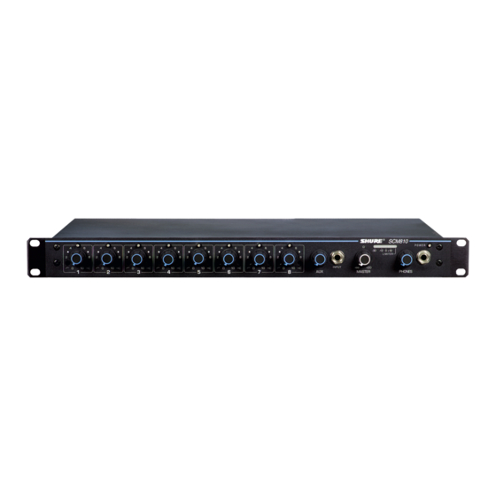
Summary of Contents for Shure SCM810AZ
-
Page 1: User Guide
EIGHT-CHANNEL MICROPHONE MIXER チ チ ャ ャ ン ン ネ ネ ル ル ・ ・ マ マ イ イ ク ク ロ ロ ホ ホ ン ン ミ ミ キ キ サ サ ー ー 2008 Shure Incorporated © 27A8868 (Rev. 2) -
Page 2: Table Of Contents
RACK MOUNTING THE MIXER ........ -
Page 3: Description
Any low-im- pedance dynamic or condenser microphone (including wireless) can be used with the SCM810/E. Multiple SCM810 mixers can be linked to other SCM810/E mixers, as well as to Shure Models FP410, SCM410, SCM800, and AMS8100 mixers. SYSTEM FEATURES •... -
Page 4: Front Panel Features
Output Level Meter: Nine-segment LED meter indicates peak output signal level. Last LED indicates limiter action. PHONES Control and 1/4-inch Phone Jack: Permits monitoring of mixer output through headphones. The PHONES knob controls head- phones output level. POWER LED: Lights green when unit is powered. -
Page 5: Dip Switches
OFF (factory setting), +16 dBm, +8 dBm, or +4 dBm (see Internal Modifica- tions for other threshold settings). Link Global/Local: Determines whether each linked SCM810 output con- tains only its own program output, or that of all linked mixers (see Mixer Linking for more information). SWITCH... -
Page 6: Installation And System Setup
RACK MOUNTING THE MIXER To mount the SCM810 in a standard 483 mm (19-inch) audio equipment rack, slide the mixer into the rack and secure it with the supplied Phillips head screws, as shown in Figure 4. Use all four screws. -
Page 7: Equalizer Functions
FIGURE 7 After equalizing the sound system, set the SCM810 to AUTOMATIC mode. Remember that the input of an automatic mixer drops by 3 dB every time the number activated inputs doubles. When using an SCM810 in MANUAL mode, the master output drops by 9 dB when all 8 inputs are activated. -
Page 8: Networking Multiple Mixers
To link multiple mixers, connect the LINK OUT of the first mixer to the LINK IN of the next mixer, and so on (see Figure 8). Leave the LINK IN jack of the first mixer and the LINK OUT jack of the last mixer unconnected. -
Page 9: Specifications
SPECIFICATIONS Measurement Conditions (unless otherwise specified): Line voltage 120 Vac, 60 Hz (SCM810) or 230 Vac, 50 Hz (SCM810E); full gain; 1 kHz, one channel activated; source impedances: Mic 150 Ω, Line 150 Ω; termina- tions: Line 10 kΩ, Phones 300 Ω (tip-sleeve and ring-sleeve), Direct Out 10 kΩ;... -
Page 10: Advanced Functions
(Shure's AMS Update publication contains additional applications of advanced logic. This publication is available by contacting Shure's Applications Group.) The fol- lowing logic functions are available for each channel: GATE OUT: Follows channel gating and goes to logic “low” (sinks current) when microphone is gated on. -
Page 11: Suggested Logic Applications
To keep certain microphones on at all times, wire the desired microphone channel's OVERRIDE IN pins together to the Logic Ground pin. The selected channels now function as they would in a non-automatic mixer (see Figure 15-Channels 1, 2 and 3 modified). - Page 12 As described in the Operating Principles section, MaxBus attempts to acti- vate only one microphone per sound source. Muting a microphone channel prevents its audio from appearing at the mixer's output. However, the mut- ed microphone still communicates with other mic channels via MaxBus. A sound source picked up by a muted microphone will not activate other mi- crophones.
-
Page 13: Voltage Selection
Shure Part No. 100 mA, 250 V 80C258 200 mA, 250 V 80BC8196 Mixer logic may be used with 15-volt CMOS logic if a pull-up resistor is used with each GATE output (see Figure 20-Channel 1 modified). 5.1 K LOGIC GROUND Ñ... -
Page 14: Internal Modifications
6 dB, R will be 330 kΩ. Local Aux Operation With linked mixers, the Aux input from a modified mixer does not link. Direct Out to Post-Fader A channel's Direct Out phone jacks can be changed from pre- to post-fader. - Page 15 SCM810 Speech Gate for Mixing Console The SCM810 can be used in conjunction with large mixing consoles to pro- vide automatic mixing for talk shows, panel discussions, and news shows. Large consoles have channel insert jacks so that external signal process- ing devices can be patched into individual channel signal paths.
- Page 16 Increase Hold Time In addition to the dip switch SW702 options of 0.4- and 1.0-second hold time, the hold time can be increased to 1.5 seconds. (More than 1.5 sec- onds is not recommended.) Decrease Hold Time The hold time can be decreased from the factory preset of 0.4 seconds to 0.3 seconds.
- Page 17 United States, Canada, Latin America, Caribbean: 5800 W. Touhy Avenue, Niles, IL 60714-4608, U.S.A. Phone: 847-600-2000 U.S. Fax: 847-600-1212 Intl Fax: 847-600-6446 Europe, Middle East, Africa: Shure Europe GmbH, Phone: 49-7131-72140 Fax: 49-7131-721414 Asia, Pacific: Shure Asia Limited, Phone: 852-2893-4290 Fax: 852-2893-4055 SHURE Incorporated http://www.shure.com 米国、...


Need help?
Do you have a question about the SCM810AZ and is the answer not in the manual?
Questions and answers