Advertisement
Quick Links
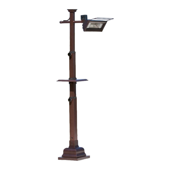
Owner's Manual
Model: 60803
READ & SAVE these instructions
Carefully read and review before attempting to
assemble, install, operate, or maintain this product.
Observe all safety instructions and information.
FAILURE TO FOLLOW WARNINGS AND
OPERATIONAL INSTRUCTIONS
CONTAINED IN THIS MANUAL CAN
RESULT IN SEVERE PROPERTY DAMAGE
AND OR PERSONAL INJURY.
***For Residential Use Only***
***Important Notice***
Do not return to place of purchase!!
Please contact our Toll Free Hotline at
1-866-985-7877 for customer
service and warranty issues.
SAVE THESE INSTRUCTIONS
Distributed by:
Well Traveled Living
Amelia Island, FL 32034
Web:
www.wtliving.com
Email:
cservice@welltraveled.net
Advertisement

Related Manuals for Fire Sense 60803


Summary of Contents for Fire Sense 60803
- Page 1 Owner’s Manual Model: 60803 READ & SAVE these instructions Carefully read and review before attempting to assemble, install, operate, or maintain this product. Observe all safety instructions and information. FAILURE TO FOLLOW WARNINGS AND OPERATIONAL INSTRUCTIONS CONTAINED IN THIS MANUAL CAN RESULT IN SEVERE PROPERTY DAMAGE AND OR PERSONAL INJURY.
- Page 2 Safety Guidelines Read this manual carefully to become knowledgeable about your heater and how to use it properly. To help recognize this information, observe the following symbols. Indicates a potentially hazardous situation which, if Indicates a potentially hazardous situation, if not not avoided, WILL result in serious injury or death.
-
Page 3: Parts List
This appliance MUST be grounded. * When using outdoors, we recommend using a certified GFI (Ground Fault Interrupt) outlet to protect against electrical shock. * All installations must be in accordance with I.E.E. safety regulations or the equivalent. CAUTION! * Avoid the use of an extension cord with this appliance. * Do not place any objects such as furniture, papers, clothing or curtains closer than 3 feet to the front and sides of the heater. - Page 4 Important Instructions 1. Read all instructions before using this heater. 12. To prevent a possible fire, do not block air 2. This heater is hot when in use. To avoid burns, intakes or exhaust in any manner. Do not use on do not let bare skin touch hot surfaces.
- Page 5 Assembling Your Heater Before beginning assembly, be sure to read and familiarize yourself with the overall assembly process and instructions in this manual. It may be helpful to have someone assist you with the assembly. You will need the following tools (NOT INCLUDED): ** #2 or #3 Philips Screwdriver (or standard slotted screwdriver) ** Adjustable Wrench Make sure you complete assembly on a clean, level, preferably carpeted location.
- Page 6 STEP 3 Use 4 – M6*12 Oval head screws (Hardware A) to attach Mounting bracket (Part 2) to head unit (Part 1) as shown in Figure 3. FIGURE 3 STEP 4 Align tilt switch (black box on head unit, Part 1) to threaded holes on Mounting bracket (Part 2) and insert M4*10 Round head screws (Hardware C) with M4 Flat washers (Hardware B) as shown in Figure 4.
- Page 7 STEP 5 Attach Round end bracket (Part 7) to Upper support tube section (Part 3) with 4 – M6*12 Oval head screws (Hardware A) as shown in Figures 5 and 6. FIGURE 6 FIGURE 5 STEP 6 Attach Top cover finishing piece (Part 6) to Upper support tube section (Part 3) with 4 – M6*12 Oval head screws (Hardware A) as shown in Figure 7.
- Page 8 STEP 8 Thread electrical cord through assembled Upper support tube section (Part 3) as show in Figure 9. FIGURE 9 STEP 9 Attach assembled Upper support tube section (Part 3) to Mounting bracket (Part 2) with 4 – M6*12 Oval head screws (Hardware A) as shown in Figure 10.
- Page 9 STEP 10 Locate Telescopic Body section 4-2 (NOTE: It has a small machined hole at the bottom of the section—see Figure 11) and slide Adjustable Table (Part 5) over the end of section 4-2 making sure the adjustable clamps on the table are facing DOWN.
- Page 10 STEP 11 Thread electrical cord from Upper support tube section down through Telescopic body (Part 4-2) and Telescopic body (Part 4-1) as shown in Figure 14. FIGURE 14 STEP 12 Attach wheel assembly to base assembly with 3 – M8*16 Hexagon screws (Hardware I). Mount Support collar flange (Part 9) to Base assembly with wheels (Part 10) as shown in Figure 15, and secure with 4 –...
- Page 11 STEP 13 Thread electrical cord through Support collar for telescopic base (Part 9) and Base assembly (Part 10) and out of the hole on the Base assembly as shown in Figure 16. FIGURE 16 STEP 14 Carefully lift assembled pole and head unit and insert lower end of pole into Support collar (Part 9) as shown in Figure 17.
- Page 12 OPERATING INSTRUCTIONS This appliance MUST be grounded. CAUTION! * When using outdoors, we recommend using a certified GFI (Ground Fault Interrupt) outlet to protect against electrical shock. * ALL installations must be in accordance with I.E.E. safety regulations or equivalent. * Avoid the use of an extension cord with this appliance.
- Page 13 Specifications Model: 60803 Voltage: 120 volts Amps: 12.5 amps Wattage: 1500 watts Lamp Type: Quartz Halogen Minimum Operational Height: 7 ft., 11 in. (95 in.) Assembled Weight: 69 lbs. Head Unit Dimensions: 25.6” x 21.6” x 18.1” Heater Assembled Dimensions: 15.75”...
- Page 14 Halogen Lamp Replacement Contact the toll free customer hotline to order approved replacement lamps and parts. Use ONLY approved original equipment and replacement halogen lamps to ensure safe, proper and maximum output operation of your heater. NOTE: Do NOT touch the new halogen lamp with your bare fingers. Oils from your hand could reduce the life of the lamp by causing a heat spot.
-
Page 15: Troubleshooting
Troubleshooting Problem Solution Unit fails to turn on. Check electrical plug connection at wall outlet for a complete, snug fit. Check to make sure the “On/Off” switch located on tilt switch is pulled OUT or in the “On” position. Check GFI and reset circuit breaker if needed. If unit is plugged into a wall outlet wired to an On/Off switch, make sure switch is in On Position. - Page 16 Distributed By: Well Traveled Living Web: www.wtliving.com 716 S 8 Street Email: cservice@welltraveled.net Amelia Island, FL 32034 Toll Free: 866‐WTL‐SUPP 1 YEAR LIMITED WARRANTY – Customers in the Continental US All components are warranted for a period of 1 year after date of purchase by the original owner against defects in materials and workmanship under normal use.
Need help?
Do you have a question about the 60803 and is the answer not in the manual?
Questions and answers