Table of Contents
Advertisement
Advertisement
Table of Contents

Related Manuals for ECS KV2 Extreme


Summary of Contents for ECS KV2 Extreme
-
Page 2: Table Of Contents
Updating and Recovering the BIOS............3-1 Headers and Connectors................1-7 ........ Using AWARD Flash to update your BIOS..3-1 Jumpers.....................1-11 ....... Using ECS EZ Flash to update your BIOS..3-2 Rear Panel....................1-12 Using ECS Top-Hat Flash to recover your BIOS........ .3-3 CHAPTER 2 The Main Menu..................3-3... - Page 3 Frequency/Voltage Control..............3-18 Install the Serial ATA (SATA) hard disks..........5-1 Load Performance Defaults...............3-19 Entering VIA Tech RAID BIOS Utility..........5-2 Load Optimized Defaults..............3-19 Create Array..................5-3 Set Supervisor/User Password............3-19 RAID 0 for performance..............5-3 Save & Exit Setup................3-20 RAID 1 for data protection...............5-4 Delete Array...................5-5 Exit Without Saving.................3-20 Select Boot Array................5-5 CHAPTER 4...
- Page 4 What is RAID..................5-14 Installing Software Drivers..............5-14 New Windows 2000/XP Installation..........5-14 Existing Windows 2000/XP/98/ME Installation........5-15 Confirming Windows 2000/XP Driver Installation......5-15 Confirming Windows 98/ME Driver Installation.........5-15 BIOS Utility Operation.................5-15 Starting BIOS Utility..............5-15 Creating RAID................5-16 Creating a RAID 0 (Stripe) Array for Performance......5-16 Creating a JBOD Array..............5-20 Creating a RAID 0+1 (Stripe-Mirror) Array........5-21 Multi-Language Translation...
- Page 5 This chapter entails the newest technology and rich features on the Photon Extreme motherboard.
- Page 6 Reference Introduction............1-1 Package Check List...........1-1 Feature Summary...........1-2 Special Features..........1-3 Major Components........1-5 Headers and Connectors........1-7 Jumpers............1-11 Rear Panel...........1-12...
-
Page 7: Chapter 1 Introduction
Thank you for choosing the ECS KV2 Extreme motherboard. Motherboard User’s Guide Installation CD The KV2 Extreme is the next generation of high performance motherboard designed to support the AMD K8 processors. This motherboard has an ATX form factor that uses a 6-layer printed circuit SATA Power Cable... -
Page 8: Feature Summary
1.3 Feature Summary • Socket 939 for AMD Athlon 64 FX processor IEEE 1394a • VIA VT6307 IEEE1394a controller • High-performance Hyper Transport CPU Interface • Supports 2 x IEEE1394a connectors • Transfer rate of 2000/1600/1200/800/400 MT/s Audio • Realtek ALC655 6-channel audio CODEC •... -
Page 9: Special Features
1.4 Special Features Extreme Power Extreme Power Extreme Power Extreme Power Extreme Power • 1 x 20-pin ATX Power Supply Connector & 4-pin 12 V Internal I/O Connector • 1 x Floppy connector- supports 360K ~ 2.88M Bytes, 3 Device plug with USB-like 6-layer PCB! Mode FDDs or LS120 ease! - Page 10 Let your PC as a Cool operations, cool Smart LAN! PC ‘health’ monitor! fileserver! appearance! All the USB 2.0 Eliminate data highway SATA RAID! connectivity you’ll ever Memory module alert! roadblocks! need! Ultra sound quality! More port options! Extreme Genius Extreme Genius Extreme Genius Extreme Genius...
-
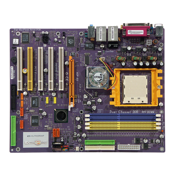
Page 11: Major Components
1. CPU socket 1.5 Major Components Socket 939 surface mount, Zero Insertion Force socket for AMD K8 Athlon 64 FX Processor support FSB 1000/800/600/400/200 MHz that allows up to 8 GB/s data transfer rates. 2. Dual channel DDR DIMM sockets These four 184-pin DIMM sockets support up to 4GB system memory using unbuffered PC3200/2700/2100/1600 DDR DIMMs. - Page 12 6. IEEE 1394a controller 12. Gigabit LAN controller The IEEE 1394a controller provides high-speed and flexible The Gigabit LAN controller delivers transfer rates up to 10/100/ PC connectivity to a wide range of peripherals and devices compliant 1000Mbps Ethernet connection. Ideal for handling large amounts of to IEEE 1394a standards.
-
Page 13: Headers And Connectors
1. ATX12V 1.6 Headers and Connectors This connector supplies the CPU operation voltage (Vcore). Don’t forget to connect the 4-pin ATX 12V connector, otherwise the system cannot boot up. 2. ATX 1 (ATXPWR, 20 pin) AC power cord should only be connected to your power supply until after ATX power cable and other related devices are firmly connected to the motherboard. - Page 14 3. IDE 1/2 (IDE1/IDE2 Connectors, 40-1 pin, Green and White) 6. Batter y Danger of explosion if battery is incorrectly replaced. Replace only with the same of equivalent type recommended by the manufacturer. These are supported by VIA8237 South Bridge. Please connect the first 7.
- Page 15 9. SATA 1/2 (Serial ATA Connectors, 7 pin, Orange) These next generation connectors are delivered by VIA 8237 South Attach the 10-1 pin 1394 cable plug from the device to this connector. Bridge support the thin Serial ATA cables for Serial ATA hard disks. The You may also connect a 1394-compliant internal hard disk to this con- current Serial ATA interface allows up to 150MB/s data transfer rate, nector.
- Page 16 These Serial ATA connectors support SATA hard disks that you may 17. Audio1 (Front Panel Audio Header, 10-1 pin) configure as a RAID set. Through the onboard SiS180 RAID controller you may create a RAID 0, RAID 1, RAID 0+1, or multiRAID configu- ration together with the RAID ATA133 connector.
-
Page 17: Jumpers
1. JP1 (Clear CMOS) 1.7 Jumpers This jumper allows you to clear the Real Time Clock (RTC) RAM in CMOS. You can clear the CMOS memory of date, time, and system setup parameters by erasing the CMOS RTC RAM data. Before clearing the CMOS data, make sure to turn the system off. -
Page 18: Rear Panel
mode, the function of this jack becomes Rear Speaker Out. 1.8 Rear Panel 6. Line out jack This jack connects a headphone or a speaker. In 6-channel mode, the function of this jack becomes Front Speaker Out. 7. Microphone jack This jack connects a microphone. - Page 19 This chapter explains the hardware setup procedure for this motherboard, such as installing the CPU, memory modules, expansion cards, as well as the jumpers...
- Page 20 Reference Installing the CPU..........2-1 Installing the CPU cooling FAN......2-1 Installing Memory Module.........2-1 Connecting IDE, Floppy and SATA cable...2-3 Installing Motherboard in a case......2-3 Connecting IDE, Floppy & SATA Device...2-4 Installing Expansion cards........2-4 Connecting the Power supply cable....2-5 Powering up............2-5...
-
Page 21: Chapter 2 Installing The Cpu
2.1 Installing the CPU 2. Make sure the CPU fan is plugged to the CPU fan connector. Please refer to the CPU 1. Angling the rod to 65-degree may feel cooling fan user’s manual for more detail Actual angle tight, continue to pull the rod to 90- installation procedure. - Page 22 Table A: DDR (memory module) QVL (Qualified Vendor List) Table B: Unbuffered DIMM Support for 939-pin The following DDR400 memory modules have been tested and qualified for use with this motherboard. Maximum Chip Selects Data DRAM Speed Size Vendor Module Name MEMCS_1L_L* MEMCS_2H_L* MEMCS_2L_L* MEMCS_2H_L* 128MB SAMSUNG...
-
Page 23: Connecting Ide, Floppy And Sata Cable
DRAM bus width) module for each deal channel. 2. Please note that those types not in the Table B will not boot up. 3. The KV2 Extreme doesn’t support three memory modules. If three memory modules are inserted, the system will not boot. -
Page 24: Connecting Ide, Floppy & Sata Device
2.6 Connecting IDE, Floppy & SATA Device 2.7 Installing Expansion cards 1. If installing two IDE devices on the same 1. Remove the slot covers from the case where you will be installing ribbon cable, one device must be set to the expansion cards. -
Page 25: Connecting The Power Supply Cable
2.8 Connecting the Power supply cable The ATX power connector is keyed for proper insertion. There are two connectors 4-pin and 20-pin ATX power cable. The plastic clip on the power connector should lock over the plastic tab on the motherboard power connector. - Page 26 In this chapter, you will learn how to adjust the BIOS (Basic Input and Output System) setup menus. It provides information on the system’s configuration status and options to setup system parameters.
- Page 27 3.3-13 Exit Without Saving..........3-20 Updating and Recovering the BIOS....3-1 3.2-1 Using AWARD Flash to update your BIOS....3-1 3.2-2 Using ECS EZ Flash to update your BIOS...3-2 3.2-3 Using ECS Top-Hat Flash to recover your BIOS..3-3 The Main Menu..........3-3 3.3-1 Standard CMOS Features........3-3 3.3-2 Advanced BIOS Features.........3-5...
-
Page 28: Entering The Bios Setup Menu
Standard CMOS Features Frequency/Voltage Control 3. Use the Award Flash Utility from the ECS support CD and download Advanced BIOS Features Load Performance Defaults the last BIOS file for this motherboard from ECS web site... -
Page 29: Using Ecs Ez Flash To Update Your Bios
3.2-2 Using ECS EZ Flash to update your BIOS 4. The Utility will update the new BIOS into the motherboard Flash The ECS EZ Flash feature allows you to easily update the BIOS without ROM. having to go through the long process of booting from a diskette and using a DOS-based utility. -
Page 30: Using Ecs Top-Hat Flash To Recover Your Bios
ROM. Date and Time 8. You can choose either AWARD Flash utility in DOS mode or ECS “EZ The Date and Time items show the current date and time on the computer. If you are Flash Utility” in windows to reflash the BIOS. - Page 31 IDE Channel 0/1 Master/Slave changes to the Windows Date and Time Properties utility. Leave this item at Auto to enable the system to automatically detect and IDE Devices [None] configure IDE devices on the channel. If it fails to find a device, change the Your computer has two IDE channels (Primary and Secondary) and each channel value to Manual and then manually configure the drive by entering the can be installed with one or two devices (Master and Slave).
-
Page 32: Advanced Bios Features
ATA 66/100 IDE Cable Msg (Enabled) Halt On [All, But Keyboard] Enables or disables the ATA 66/100 IDE Cable Msg. This message will appear during This item defines the operation of the system POST (Power On Self Test) routine. reboot when you use 40-pin cable on your 66/100 hard disks. You can use this item to select which types of errors in the POST are sufficient to halt the system. - Page 33 searches for an operating system at start-up time. must elapse before a held-down key begins generating repeat characters Security Option [Setup] Boot Other Device [Enabled] If you have installed password protection, this item defines if the password is When enabled, the system searches all other possible locations for an operating required at system start up, or if it is only required when a user tries to enter the system if it fails to find one in the devices specified under the First, Second, and Setup Utility.
-
Page 34: Advanced Chipset Features
3.3-3 Advanced Chipset Features AGP & P2P Bridge Control (Press Enter) Scroll to this item and press <Enter> to view the following screen: These items define critical timing parameters of the mainboard. You should leave the items on this page at their default values unless you are Phoenix-AwardBIOS CMOS Setup Utility Advanced Chipset Features very familiar with the technical specifications of your system hardware. - Page 35 AGP Driving Control (Auto) Phoenix-AwardBIOS CMOS Setup Utility DRAM Clock/Drive Control This item is used to signal driving current on AGP cards to auto or manual. Some AGP cards need stronger than normal driving current in order to operate. We Current CPU Frequency Item Help recommend that you set this item to the default.
- Page 36 strobe). It is recommended that you leave this item at the default value. The Upstream/Downstream LDT Bus Width (16 bit) 2T setting requires faster memory that specifically supports this mode. The LDT bus (Lighting Data Transport) is the bus between the North and South RAS# to CAS# delay (Trcd)(Auto) Bridge, and boosts no less that 6.4 GB/sec on a 16 bit upstream and a 16 bit This item specifies the RAS# to CAS# delay to Rd/Wr command to the same bank.
-
Page 37: Integrated Peripherals
Init Display First (PCI Slot) Phoenix-AwardBIOS CMOS Setup Utility VIA OnChip IDE Device Use this item to specify whether your graphics adapter is installed in one of the PCI slots or is integrated on the motherboard Item Help OnChip VIA SATA [Enabled] SATA Mode [IDE]... - Page 38 IDE Prefetch Mode (Enabled) VIA OnChip PCI Device (Press Enter) The onboard IDE drive interface supports IDE prefetching, for faster drive access. Scroll to this item and press <Enter> to view the following screen: If you install a primary and secondary add-in IDE interface, set this field to Phoenix-AwardBIOS CMOS Setup Utility Disabled if the interface does not support prefetching.
- Page 39 OnChip USB Controller (All Enabled) SuperIO Device (Press Enter) Enable this item if you plan to use the Universal Serial Bus ports on this motherboard. Scroll to this item and press <Enter> to view the following screen: USB 2.0 Support (Enabled) Phoenix-AwardBIOS CMOS Setup Utility SuperIO Device Enable this item if your system supports USB 2.0.
-
Page 40: Power Management Setup
3.3-5 Power Management Setup Parallel Port Mode (ECP) Enables you to set the data transfer protocol for your parallel port. There are four This option lets you control system power management. The system has options: SPP (Standard Parallel Port), EPP (Enhanced Parallel Port), ECP (Extended various power-saving modes including powering down the hard disk, turning Capabilities Port) and ECP+EPP. - Page 41 to hold the power button down for four seconds to cause a software power down. HDD Power Down [Disabled] Run VGABIOS if S3 Resume [Auto] The IDE hard drive will spin down if it is not accessed within a specified length of time.
- Page 42 PS2KB Wakeup Select (Hot key) PowerOn by PCI Card (Enabled) This option allows you to set hot key combination to turn on the system by Use this item to enable PCI activity to wakeup the system from a power saving keyboard.
-
Page 43: Pnp/Pci Configurations
3.3-6 PNP/PCI Configurations IRQs Activity Monitoring (Press Enter) This screen enables you to set IRQs that will resume the system from a power saving These options configure how PnP (Plug and Play) and PCI expansion cards mode. Phoenix-AwardBIOS CMOS Setup Utility operate in your system. -
Page 44: Pc Health Status
3.3-7 PC Health Status Resources Controlled By [Auto(ESCD)] On motherboards that support hardware monitoring, this item lets you You should leave this item at the default Auto (ESCD). Under this setting, the system dynamically allocates resources to Plug and Play devices as they are monitor the parameters for critical voltages, temperatures and fan speeds. -
Page 45: Frequency/Voltage Control
3.3-8 Frequency/Voltage Control Auto Detect PCI/DIMM Clk (Enabled) When this item is enabled, BIOS will disable the clock signal of free DIMM and PCI This item enables you to set the clock speed and system bus for your system. slots. The clock speed and system bus are determined by the kind of processor Spread Spectrum (Enabled) you have installed in your system. -
Page 46: Load Performance Defaults
3.3-9 Load Performance Defaults 3.3-11 Set Supervisor/User Password This option opens a dialog box that lets you install performance defaults for When this function is selected, the following message appears at the center all appropriate items in the Setup Utility: Press <Y> and the <Enter> to of the screen to assist you in creating a password. -
Page 47: Save & Exit Setup
Supervisor Password has higher priority than User Password. You can use Supervisor Password when booting the system or entering BIOS Setup to modify all settings. Also you can use User Password when booting the system or entering BIOS Setup but can not modify any setting if Supervisor Password is enabled. - Page 48 This chapter delivers contents of the ECS support CD.
-
Page 49: Running The Software Cd
Reference Software CD Information........4-1 Running the Software CD........4-1 Setup Tab............4-1 Application Tab..........4-2 Read Me Tab............4-2 Software Utilities Introduction......4-2... -
Page 50: Software Cd Information
4.1 Software CD Information 4.3 Setup Tab The support software CD-ROM that is included in the motherboard package The setup tab shows three buttons - Setup, Browse CD, Exit. contains all the drivers and utility programs needed to properly run the Setup button: Click the Setup button to run the software installation bundled products. -
Page 51: Application Tab
2. Click Next . The following screen appears: 4. Follow the instructions on the screen to install the items. Drivers and software are automatically installed in sequence. Follow the onscreen instructions, confirm commands and allow the computer to restart a few times to complete the installation. Browse CD button: The Browse CD button is the standard Windows command that allows you to open Windows... - Page 52 erase the current BIOS and fail to write a new BIOS, or write a new WinCinema BIOS that is incorrect, your system will malfunction. Refer to Chapter 3 WinDVD Creator Plus “Using BIOS” for more information. WinDVD Creator Plus is designed for people who want to make their own WinFlash Utility DVDs but who don’t want to learn complicated programs.
- Page 53 Pro Magic Show Shifter This amazing software not only provides users with convenient and instant ShowShifter, the award winning software, combines viewing TV, video, restoration of your computer, but also restores within seconds important CD, MP3 and digital pictures into one easy to use application. With a little data back to the preferred state at a specific point in time.
- Page 54 other is to update a new BIOS. EZ-Flash only supports under Windors 2000/XP. MyPic User can build their own BIOS image which will display a customized picture at the boot-up time. MyPic only supports Windows 2000/XP which is an application to make a rom file.
- Page 55 In this chapter, you will learn how to create Serial ATA/Ultra RAID and the type of RAID we support.
- Page 56 Reference Support Operating Systems......5-13 What is RAID..........5-14 VIA RAID Configurations.........5-1 Installing Software Drivers.......5-14 5.1-1 Install the Serial ATA (SATA) hard disks.....5-1 5.8-1 New Windows 2000/XP Installation....5-14 5.1-2 Entering VIA Tech RAID BIOS Utility....5-2 5.8-2 Existing Windows 2000/XP/98/Me 5.1-3 Create Array..............5-3 Installation..............5-15 5.1-4 RAID 0 for performance...........5-3 5.8-3...
-
Page 57: Via Raid Configurations
JBOD will not increase any performance or data security. 5.1 VIA RAID Configurations 5.1-1 Install the Serial ATA (SATA) hard disks The motherboard includes a high performance Serial ATA RAID controller The VIA VT8237 Southbridge chipset supports Serial ATA hard disk drives. integrated in the VIA VT8237 Southbridge chipset. -
Page 58: Entering Via Tech Raid Bios Utility
new Serial ATA cable (4-conductor) which supports the Serial ATA 5.1-2 Entering VIA Tech RAID BIOS Utility protocol and a Serial ATA power cable. Boot-up your computer Either end of the Serial ATA data cable can be connected to the SATA During POST, press <TAB>... -
Page 59: Create Array
View Array 5.1-4 RAID 0 for performance Move to the next item ↑↓ Select the second option item Array Mode, then press the <Enter> Enter Confirm the selection key. The RAID system setting pop-up menu appears. Exit 5.1-3 Create Array In the VIA RAID BIOS utility main menu, select Create Array then press the <Enter>... -
Page 60: Raid 1 For Data Protection
Use arrao keys to move selection bar on items and press <Enter> to select. Select RAID 1 for data protection from the menu and press <En- ter>. Select next task from pop-up menu. The task Create only Select Start Create Process and press <Enter> to setup hard disk for creates the mirrored set without creating a backup. -
Page 61: Delete Array
5.1-7 Select Boot Array In the VIA RAID BIOS utility main menu, select Boot Array then press the <Enter> key. The focus is directed to the list of channel used for IDE RAID arrays. Press the <Enter> key to select a RAID array for boot. The Status Press “Y”... -
Page 62: Serial Number View
5.1-8 Serial Number View 5.1-9 Duplicate Critical RAID 1 Array In the VIA RAID BIOS utility main menu, select Serial Number View When booting up the system, BIOS will detect if the RAID 1 array has any then press the <Enter> key. The focus is directed to the list of inconsistencies between user data and backup data. -
Page 63: Rebuild Broken Raid 1 Array
5.1-10 Rebuild Broken RAID 1 Array When booting up the system, BIOS will detect if any member disk drives of RAID has failed or is absent. If BIOS detects any disk drive failures or missing disk drives, the status of the array will be marked as broken. If BIOS detects a broken RAID 1 array but there is a spare hard drive available for rebuilding the broken array, the spare hard drive will automati- cally become the mirroring drive. -
Page 64: Installing Raid Software & Drivers
Highlight the target hard drive and press <Enter>, a warning message will 2. Destroy the Mirroring Relationship: appear. Press Y to use that hard drive to rebuild, or press N to cancel. Please This item cancels the data mirroring relationship of the broken array. For note selecting option Y will destroy all the data on the selected hard drive. - Page 65 • RAID0 and RAID1 functions Insert the ECS CD and click on the Setup to install the software. Existing Windows XP Driver Installation Insert the ECS CD into the CD-ROM drive. The CD will auto-run and the setup screen will appear.
-
Page 66: Using Via Raid Tool
The InstallShield Wizard will begin automatically for installation. Click 5.3 Using VIA RAID Tool on the Next button to proceed the installation in the welcoming window. Once the installation is complete, go to Start---> Programs---> VIA---> raid_tool.exe to enable VIA RAID Tool. Put a check mark in the check box to install the feature you want. - Page 67 The main interface is divided into two windows and the toolbar above Click on button to determine the viewing type of left contain the main functions. Click on these toolbar buttons to execute their windowpane. There are two viewing types: By controllers and by device. specific functions.
- Page 68 You may also use the same button to view the statuses of Click on the plus (+) symbol next to Array 0; RAID 1 to see the details of Array 0--RAID 1. each disk. 5-12...
-
Page 69: Introduction For Sis180 Raid Function
RAID fully supports Serial ATA/150 and Ultra ATA/133 specification of 5.4 Introduction for SiS180 RAID Function up to 150MB/sec per drive, depending on individual drive specifications. The 180 S-ATA controller is a hybrid solution that combines two independent SATA ports and one Ultra ATA port for support of up to two 5.5 Features Serial ATA (Serial ATA RAID) and two Ultra ATA (Ultra ATA RAID) ♦... -
Page 70: What Is Raid
insurance. 5.7 What is RAID? 5. JBOD: (Just a Bunch of Drives). Also known as “Spanning”. Two or This section will give you an overview about the RAID system and introduce more hard drives are required. Several hard disk types configured as a the basic background and glossary which you need to know before using single hard disk. -
Page 71: Existing Windows 2000/Xp/98/Me Installation
5.8-4 Confirming Windows 98/Me Driver Installation that appears on screen, and then press the Enter key. 5. Press Enter to continue with installation or if you need to specify 1. From Windows 98/Me, open the Control Panel from “My Com- any additional devices to be installed, do so at this time. -
Page 72: Creating A Raid 0 (Stripe) Array For Performance
5.9-2 Create RAID ♦ SIS 180 controller support RAID 0, RAID 1, JBOD and RAID 0+1. 5.9-3 Creating a RAID 0 (Stripe) Array for Performance ♦ SIS 180 enables users to create striped arrays with 2, 3, or 4 drives. To create an array for best performance, follow these steps: 1. - Page 73 8. Besides, you also can select <2>Manual Create, see following 5. Use < > < > to select disk, and press <Enter> to select disk, <Q> steps. to exit. When you press <Enter> on the disk you wanted, the RAID Type will be changed from Single to RAID 0.
- Page 74 7. Starting splitting action, the following frame will be shown. 9. Press <Q> again to exit this BIOS utility and the red message frame will show. Press <Y> and <Enter> to save changes. 10. Once the array has been created, you will need to FDISK and format the array as if it were a new single hard drive.
-
Page 75: Creating A Raid 1 (Mirror) Array
5.9-4 Creating a RAID 1 (Mirror) Array ♦ SIS180 enables users to create Mirror arrays with 2 drives only. To create a Mirror array, follow these steps: 1. Press <A> to start creating a RAID array. 2. Press <3> and <Enter> to select Mirror. 3. -
Page 76: Creating A Jbod Array
6. Starting duplicating action, the following frame will be showing. 8. Press <Q> again to exit this BIOS utility and the red message frame will show as the same as the creation of the RAID 0 array. Press <Y> and <Enter> to save changes. 9. -
Page 77: Creating A Raid 0+1 (Stripe-Mirror) Array
on step 5. Besides, you also can select <2>Manual Create, see 5. After all steps finished, press <Q> until escape the setup menu and following steps. JBOD array will be show on the top of the main frame. 4. Use < > < > to select disk, and press <Enter> to select disk, <Q> 6. - Page 78 5. Use < > < > to select disk, and press <Enter> to select disk. <Q> to exit. When you press <Enter> on the disk you wanted, the RAID Type will be changed from Single to RAID 0+1. 3. You will have two selections to create a RAID 0+1 array. The default value is <1>.
- Page 79 7. Press <Q> again to exit this BIOS utility and the red message frame will show as the same as the creation of the RAID 0 array. Press <Y> and <Enter> to save changes. Remark: On DOS, it can’t support RAID 0+1 function. So you can’t use FDISK to format the array as if it were a new single hard driver.
- Page 80 Résumé des caractéristiques • Socket 939 pour processeur AMD Athlon 64 FX IEEE 1394a • Contrôleur VIA VT6307 IEEE1394a • Interface de CPU HyperTransport de Haute performance • Prend en charge 2 x connecteurs IEEE1394a • Vitesse de transfert de 2000/1600/1200/800/400 MT/s Audio •...
- Page 81 E/S interne • 1 x Connecteur d’alimentation ATX 20 broches & Connecteur 12 V 4 broches • 1 x connecteur de lecteur de disquette- prenant en charge 360K ~ 2,88M octets, 3 Lecteurs de disquettes Modes ou LS120 • 3 x connecteurs IDE •...
- Page 82 Zusammenfassung der Merkmale • Sockel 939 für AMD Athlon 64 FX Prozessor IEEE 1394a • VIA VT6307 IEEE1394a Controller • Hochleistungs-HyperTransport-CPU-Schnittstelle • Unterstützt 2 x IEEE1394a Anschlüsse • Übertragungsgeschwindigkeiten: 2000/1600/1200/800/400 MT/s • Realtek ALC655 6-Kanal Audio CODEC Audio Chipsatz • VIA K8T800 PRO &...
- Page 83 Internes I/O • 1 x 20-Pin ATX Netzteilanschluss & 4-Pin 12 V Anschluss • 1 x Floppylaufwerkanschluss, unterstützt 360K ~ 2.88M Bytes, 3 Modus Festplatten oder LS120 • 3 x IDE Anschlüsse • 4 x Seriell ATA Anschluss • 2 x USB 2.0 Anschluss, unterstützt zusätzlich 4 USB Anschlüsse •...
- Page 84 Indice delle caratteristiche Presa 939 per processore AMD Athlon 64 FX • IEEE 1394a • Controller VIA VT6307 IEEE1394a Interfaccia per CPU HyperTransport ad elevata prestazione • • Supporta 2 xconnettori IEEE1394a Velocità di trasferimento 2000/1600/1200/800/400 MT/s • • Realtek ALC655 6- canale audio CODEC Audio Chipset •...
- Page 85 I/O interno • 1 x connettore di alimentazione 20-pin ATX e connettore 4-pin da 12 V • 1 x connettore floppy - supporta 360K ~ 2.88M Byte, 3 Mode FDDs o LS120 • 3 x connettori IDE • 4 x connettori seriali ATA •...
- Page 86 Resumen de Características • Socket 939 para procesador AMD Athlon 64 FX IEEE 1394a Controlador VIA VT6307 IEEE1394a • • Interfaz HyperTransport CPU de Alto Rendimiento Soporta 2 x conectores IEEE1394a • • Índice de transferencia de 2000/1600/1200/800/400 MT/s Realtek ALC655 6-channel audio CODEC •...
- Page 87 I/O Interno 1 x Conector de Suministro 20-pin ATX & Conector 4-pin 12 V • • 1 x conector Floppy - soporta 360K ~ 2.88M Bytes, FDD de 3 Modos o LS120 • 3 x conectores IDE 4 x conectores Serial ATA •...
- Page 88 Sumário de Características • Tomada de parede 939 para processador AMD Athlon 64 FX IEEE 1394a Controlador VIA VT6307 IEEE1394a • • Interface CPU HyperTransport de alta performance Suporta 2 x conectores IEEE1394a • • Taxa de transferência de 2000/1600/1200/800/400 MT/s CODEC 6 canais áudio Realtek ALC655 •...
- Page 89 I/O interno 1 x Conector de Fonte de Alimentação 20 pinos ATX & • Conector 4 pinos 12 V 1 x Conector flexível - suporta 360K ~ 2.88M Bytes, FDDs de 3 • Modos ou LS120 • 3 x Conectores IDE •...
- Page 90 特徴概要 • AMD Athlon 64 FXプロセッサ用のSocket 939 • IEEE 1394a VIA VT6307 IEEE1394a コントローラ プロセッサ • 高性能HyperTransport CPU インターフェース • つのIEEE1394a コネクタをサポート • 転送率が2000/1600/1200/800/400 MT/s • • オーディオ VIA K8T800 PRO & 8237 Realtek ALC655の6チャネル・オーディオCODEC チップセット • • North Bridge: VIA K8T800 PRO AC’97 2.3 規格に準拠...
- Page 91 • 内部入出力 1 つの20ピンATX 電源サプライコネクタと4ピン12 V コネ クタ • 1つのフロッピーディスクドライブコネクタ、360Kから 2.88Mバイトの3 Mode FDDとLS120をサポート • 3つのIDEコネクタ • 4つのシリアルATAコネクタ • 2つのUSB 2.0ヘッダーでさらなる4つのUSBポートを増設 可能 • 2つの1394a ヘッダー • 1つEZ-Watcher ヘッダー(オプション) • 1 つのSMBusヘッダー • 1 つの前面パネルスイッチ/LED ヘッダー • 1つのフロントパネルオーディオヘッダー • CD入力/AUX 入力ヘッダー • CPUFAN/NB_FAN/CASFAN コネクタ...
- Page 92 특성 요약 • AMD 애슬론 64 FX 프로세서를 위한 소켓 939 • IEEE 1394a VIA VT6307 IEEE1394a 컨트롤러 • 고성능의 HyperTransport CPU 인터페이스 • 2 x IEEE1394a 커넥터 지원 • 전송 속도 2000/1600/1200/800/400 MT/s • • 오디오 VIA K8T800 PRO & 8237 Realtek ALC655 6 채널...
- Page 93 • 내부 I/O 1 x 20 핀 ATX 파워 써플라이 커넥터 및 4 핀 12 V 커넥터 • 1 x 플로피 커넥터- 360K ~ 2.88M Bytes, 3 모드 FDD 또 는 LS120 지원 • 3 x IDE 커넥터 • 4 x 시리얼 ATA 커넥터 •...
- Page 94 功能摘要 • AMD Athlon 64 FX 處理器用Socket 939 • IEEE 1394a ㆗央處理器 VIA VT6307 IEEE1394a 控制器 • 高效能HyperTransport CPU介面 • 支援2個IEEE1394a 連接器 • 傳輸速率2000/1600/1200/800/400 MT/s • 音訊 • VIA K8T800 PRO & 8237 採Realtek ALC655 6-聲道音訊CODEC 晶片組 • 北橋晶片: VIA K8T800 PRO •...
- Page 95 內部輸出入 • 1個20針ATX 電源供應器連接器及1個4針12 V連接器 介面 • 1個軟碟機連接器,可支援360K㉃2.88M位元組之3 Mode 軟碟機及LS120軟碟機 • 3個IDE連接器 • 4個序列ATA 連接器 • 2個USB 2.0接頭,可支援4個額外的USB埠 • 2個1394a接頭 • 1個EZ-Watcher接頭(可選) • 1個SMBus接頭 • 1個前面板開關及1個LED 接頭 • 1個前面板音訊接頭 • CD音源輸入/AUX音源輸入接頭 • 處理器冷卻風扇/北橋晶片風扇/機殼風扇連接器 • 主機板尺寸 ATX 尺寸 • 305mm x 244mm...
- Page 96 功能摘要 • 用于AMD Athlon 64 FX 处理器的 Socket 939 插座 IEEE 1394a • VIA VT6307 IEEE1394a 控制器 • 高性能超级传输(HyperTransport)CPU 接口 • 支持 2 个 IEEE1394a 接口 • 传输速率 2000/1600/1200/800/400 MT/s 音頻 • • Realtek ALC655 6 声道音频编解码器 VIA K8T800 PRO & 8237 芯片组...
- Page 97 集成 I/O • 1 个 20 针 ATX 电源接口和 1 个 4 针 12 V 接口 • 1 个软驱接口- 支持 360K ~ 2.88M 字节,3 Mode FDD 或 LS120 • 3 个 IDE 接口 • 4 个串行 ATA 接口 • 2 个 USB 2.0 接头,支持另外 4 个 USB 端口 •...
- Page 98 Характеристики • Разъем 939 для процессоров AMD Athlon 64 FX IEEE 1394a • Контроллер VIA VT6307 IEEE1394a • Интерфейс HyperTransport CPU с высокой пропускной • Поддержка 2 разъемов IEEE1394a способностью • Скорость передачи данных 2000/1600/1200/800/400 MT/сек Aудиo • 6-канальный аудио CODEC Realtek ALC655 •...
- Page 99 Стандарт • 1 20-штырьковое гнездо питания ATX и 4-штырьковое Внутренние гнездо 12 V гнезда входа/ • 1 гнездо подключения накопителя НГМД с поддержкой выхода форматов 360K ~ 2.88MБ, 3 формата FDD или LS120 • 3 гнезда IDE • 4 гнезд Serial ATA •...
- Page 100 Cechy • Gniazdo 939 dla procesorów AMD Athlon 64 FX IEEE 1394a • Kontroler VT6307 IEEE1394a firmy VIA • Złącze szybkiego transpotu danych HyperTransport CPU • Obsługa 2 złącz IEEE1394a Interface • Szybkość przesyłania danych 2000/1600/1200/800/400 MT/s Audio • 6-kanałowy audio CODEC Realtek ALC655 •...
- Page 101 Wewnętrzne • 1 gniazdo 20-nóżkowe zasilacza ATX i 4-nóżkowe gniazdo zasilania 12 V gniazda • 1 gniazdo napędu dyskietek, obsługuje formaty 360K ~ 2.88M We/Wy Bajt, 3 Mode FDD lub LS120 • 3 złącza IDE • 4 złącz Serial ATA •...
- Page 102 Souhrn vlastností • Patice 939 pro procesory AMD Athlon 64 FX IEEE 1394a • Řadič VIA VT6307 IEEE1394a • Vysoce výkonné rozhraní HyperTransport CPU • Podpora 2 portů IEEE 1394a • Přenosové rychlosti 2000/1600/1200/800/400 MT/s Zvuk • 6kanálový zvukový kodek Realtek ALC655 Čipová...
- Page 103 Interní • 1x 20kolíkový napájecí konektor ATX a 4kolíkový konektor 12 V vstupy/ • 1x konektor floppy diskových mechanik – podpora 360 kB až 2,88 výstupy MB, 3 režimy FDD nebo LS120 • 3x konektor IDE • 4x konektor Serial ATA •...
- Page 104 Sumarul caracteristicilor Unitatea • Soclu 939 pentru procesoare AMD Athlon 64 FX IEEE 1394a • Controler VIA VT6307 IEEE1394a • Interfaţă CPU HyperTransport de înaltă performanţă centrală (CPU) • suportă două conectoare IEEE1394a • Viteză de transfer de 2000/1600/1200/800/400 MT/s Set de chipuri •...
- Page 105 I/O internă • Un conector cu 20 ace pentru alimentare cu energie şi conector de 12 V cu 4 ace • Un conector Floppy, pentru dischete de 360 KB–2,88 MB, FDD cu 3 moduri sau LS120 Trei • sloturi IDE •...
- Page 106 Параметри • сокет 939 за процесор AMD Athlon 64 FX IEEE 1394a Процесор • Контролер VIA VT6307 IEEE1394a • високопроизводителен интерфейс HyperTransport • Поддръжка на 2 порта IEEE1394a • скорост на обмен на данни 2000/1600/1200/800/400 MT/s Аудио • 6-канален аудио CODEC Realtek ALC655 Чипсет...
- Page 107 Интегриран • 1 конектор 20-pin ATX Power Supply и конектор 4-pin 12 V • 1 конектор за флопидисково устройство с поддръжка на Вход/Изход устройства 360K ~ 2.88M Bytes, 3 Mode или LS120 контролер • 3 конектора IDE • 4 конектора Serial ATA •...
- Page 108 Jellemzők összefoglalása Központi • 939 foglalat AMD Athlon 64 FX processzornak IEEE 1394a • VIA VT6307 IEEE1394a vezérlő • Nagy teljesítményű HyperTransport technologiás központi egység(CPU) • Két IEEE1394a csatlakozót támogat egység interfész • 2000/1600/1200/800/400 MT/s átviteli sebesség • Realtek ALC655 6 csatornás audio CODEC Audio Lapkakészlet •...
- Page 109 Belső I/O • Egy 20 tűs ATX tápforrás csatlakozó és négytűs 12 V-os csatlakozó • Egy floppy meghajtó 360 kB–2,88 MB lemezeknek, 3 üzemmódú FDD meghajtók vagy LS120 • Három IDE foglalat • Négy soros ATA csatlakozó • Két USB 2.0 csatlakozó, és további 4 USB porttal tud működni •...
-
Page 110: Legal Notices
Legal Notices Copyright Federal Communications Commision (FCC) This publication, including all photograph, illustrations and software, is This equipment has been tested and found to comply with the limits for protected under international copyright laws, with all rights reserved. a Class B digital device, pursuant to Part 15 of the FCC Rules. These Neither this manual, nor any of the material contained herein, may be limits are designed to provide reasonable protection against harmful reproduced without written consent of the author. - Page 111 Declaration of Conformity This device complies with part 15 of the FCC rules. Operation is subject to the following conditions: - This device may not cause harmful interference, and - This device must accept any interference received, including inter- ference that may cause undesired operation. Canadian Department of Communications This class B digital apparatus meets all requirements of the Canadian Interference-causing Equipment Regulations.
Need help?
Do you have a question about the KV2 Extreme and is the answer not in the manual?
Questions and answers