
Subscribe to Our Youtube Channel
Related Manuals for Neumann.Berlin TLM 107


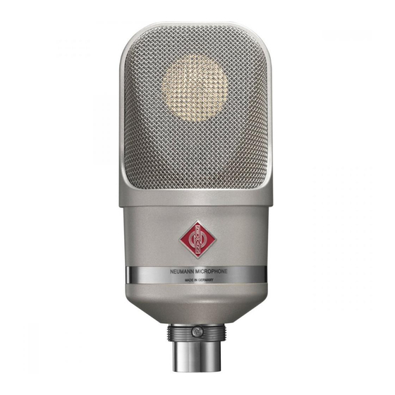
Summary of Contents for Neumann.Berlin TLM 107
- Page 1 TLM 107 Bedienungsanleitung Operating Manual georg neumann gmbh · ollenhauerstr. 98 · 13403 berlin · germany fon +49 (0)30 / 41 77 24-0 · fax -50 · headoffice@neumann.com · www.neumann.com...
- Page 2 Reparatur- und Servicearbeiten dürfen nur von erfahrenem und autorisiertem Fachpersonal Mit seinem transformatorlosen Konzept ermögli- durchgeführt werden. Wenn Sie das Gerät eigen- cht das TLM 107 eine besonders saubere, verfär- mächtig öff nen oder umbauen, erlischt die Ge- bungsfreie Klangübertragung und höchste Aus- währleistung.
- Page 3 Inbetriebnahme Störschallunterdrückung Der Übertragungsbereich des TLM 107 reicht bis Mikrofon einrichten unter 20 Hz. Entsprechend empfi ndlich ist das Mi- Befestigen Sie das Mikrofon auf einem ausrei- krofon natürlich auch für tieff requente Störungen chend stabilen und standfesten Stativ. Verwen- wie Körperschall oder Wind- und Popgeräusche. den Sie ggf.
- Page 4 Fehlercheckliste ▶ ▶ Fehler Mögliche Ursachen Abhilfe Keine Phantom-Speisespannung am Überprüfen Sie die entsprechenden Einstel- Funktion Mischpult oder am Speisegerät nicht lungen auf dem Kanalzug. eingeschaltet (LEDs leuchten nicht). Das Speisegerät ist nicht mit dem Überprüfen Sie Netzanschluss oder Batterie des Netzanschluss verbunden oder Speisegeräts.
- Page 5 Das Mikrofon besitzt einen symmetrischen, über- Ausgewähltes Zubehör* tragerlosen Ausgang. Der 3-polige XLR-Steck- (Fotos im Anhang) verbinder weist folgende normgerechte Belegung auf: Elastische Aufhängungen Pin 1: 0 V/Masse EA 4 ......ni ....Best.-Nr. 008641 Pin 2: Modulation (+Phase) EA 4 bk .....sw ....Best.-Nr. 008642 Pin 3: Modulation (–Phase) Mikrofonneigevorrichtung...
-
Page 6: Safety Instructions
Brief description purchased. Please read the instructions care- fully and completely before using the equipment. The TLM 107 is a condenser studio microphone Please keep this manual where it will be acces- with transformerless (TLM) circuit technology. On sible at all times to all current and future users. -
Page 7: Shutdown And Storage
Setup Suppressing noise interference The frequency response of the TLM 107 extends Mounting the microphone below 20 Hz. The microphone is of course corre- Attach the microphone to a stable, sturdy stand. spondingly sensitive to low-frequency interfer- Use an elastic suspension, if necessary, for the ence such as structure-borne noise and wind or mechanical suppression of structure-borne noise. -
Page 8: Troubleshooting
Troubleshooting ▶ ▶ Problem Possible causes Solution Microphone not The phantom power supply voltage is Check the corresponding channel settings operating not switched on at the mixing console or at the power supply equipment (LEDs not lit up). The power supply equipment is not Check the connection to the power supply connected to the power supply line or line or check the battery of the power supply... - Page 9 The microphone has a balance d, transformerless Selected Accessories* output. The 3-pin XLR connector has the following (see photos in appendix) standardized pin assignments: Elastic Suspensions Pin 1: 0 V/Ground Pin 2: Modulation (+phase) EA 4 ......ni ....Cat. No. 008641 EA 4 bk .....blk ....Cat.
- Page 10 10. Frequenz- und Polardiagramme 10. Frequency responses and polar patterns gemessen im freien Schallfeld nach IEC 60268-4, Toleranz ±2 dB measured in free-fi eld conditions (IEC 60268-4), tolerance ±2 dB 10 10...
- Page 11 11 11...
- Page 12 gemessen im freien Schallfeld nach IEC 60268-4, Toleranz ±2 dB measured in free-fi eld conditions (IEC 60268-4), tolerance ±2 dB 12 12...
- Page 13 13 13...
- Page 14 Abb. 1 / Fig. 1 Abb. 2 / Fig. 2 14 14...
- Page 15 EA 4 (bk) MNV 87 DS 120 SG 2 MF 4 MF 5 STV... PS 15 PS 20 a WS 47 BS 48 i BS 48 i-2 15 15...
- Page 16 N 248 IC 3 mt IC 4 (mt) Haftungsausschluss Konformitätserklärung Die Georg Neumann GmbH übernimmt keinerlei Haft ung für Folgen eines Die Georg Neumann GmbH erklärt, dass dieses Gerät die anwendba- unsachgemäßen Gebrauchs des Produkts, d.h. die Folgen eines Gebrauchs, ren CE-Normen und -Vorschrift en erfüllt.
Need help?
Do you have a question about the TLM 107 and is the answer not in the manual?
Questions and answers