Table of Contents
Advertisement
Quick Links
SEIKAKU TECHNICAL GROUP LIMITED
NO. 1, Lane 17, Sec. 2, Han Shi West Road, Taichung 40151, Taiwan
http://www.altoproaudio.com Tel: 886-4-22313737
email: alto@altoproaudio.com Fax: 886-4-22346757
All rights reserved to ALTO. All features and content might be changed
without prior notice. Any photocopy, translation, or reproduction of part of this
manual without written permission is forbidden. Copyright
c
2007 Seikaku Group
NF02949-1.2
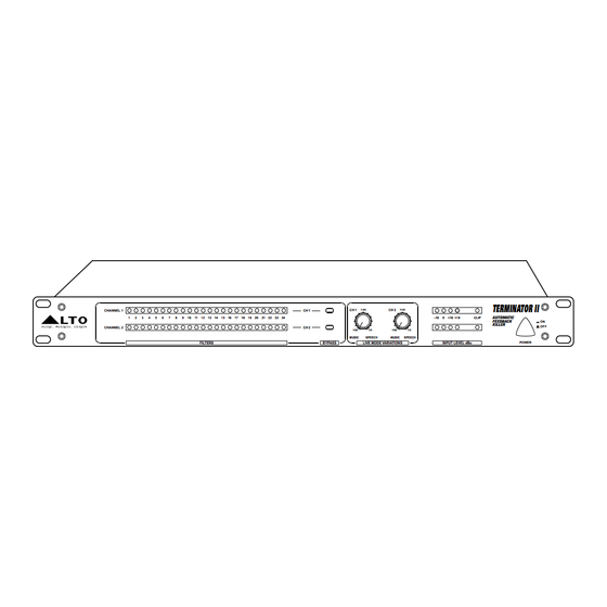
TERMINATOR II
DIGITAL PROCESSOR
Automatic Feedback Killer
CHANNEL 1
1
2
3
4
5
6
7
8
9
10
11 12 13 14 15 16 17 18 19 20
CHANNEL 2
FILTERS
User's Manual
TERMINATOR II
CH 1
CH 1
1/40
CH 2
1/40
AUTOMATIC
21 22 23 24
-10
0
+10
+18
CLIP
FEEDBACK
KILLER
CH 2
1/80
1/5
1/80
1/5
MUSIC
SPEECH
MUSIC
SPEECH
BYPASS
LIVE MODE VARIATIONS
INPUT LEVEL dBu
www.altoproaudio.com
Version 1.2 April 18, 2008
English
ON
OFF
POWER
Advertisement
Table of Contents

Subscribe to Our Youtube Channel
Related Manuals for Alto TERMINATOR II


Summary of Contents for Alto TERMINATOR II
- Page 1 User's Manual TERMINATOR II DIGITAL PROCESSOR Automatic Feedback Killer TERMINATOR II CHANNEL 1 CH 1 CH 1 1/40 CH 2 1/40 AUTOMATIC 11 12 13 14 15 16 17 18 19 20 21 22 23 24 CLIP FEEDBACK KILLER CHANNEL 2...
- Page 2 IMPORTANT SAFETY INSTRUCTION CAUTION WARNING To reduce the risk of electric shock RISK OF ELECTRIC SHOCK and fire, do not expose this equipment DO NOT OPEN to moisture or rain. TO REDUCE THE RISK OF ELECTRIC SHOCK PLEASE DO NOT REMOVE THE COVER OR Dispose of this product should THE BACK PANEL OF THIS EQUIPMENT.
-
Page 3: Quick Start
2 seconds till only the FIXED filter leds keep on lighting or misuse of this product. 2.5 If you need to RESET completely TERMINATOR II and start a new SET UP , Normal tear and wear. press and hold the BYPASS button for more than 4 seconds till all 24 filter The product has been altered or modified in any way. -
Page 4: Technical Specification
20 Hz to 20 kHz, +/- 0.5 dB maintaining a simple and intuitive control interface. Inter channel Crosstalk 100 dB, A-weighted The TERMINATOR II provides up to 24 filters per channel (CH1 & CH2), offers Crosstalk input to output 100 dB, A-weighted Power Requirement... -
Page 5: Control Elements
INPUT LEVEL dBu POWER amplifiers. 3- Set the sensitivity at +4 dBu on the TERMINATOR II and adjust the L-R fader 1 Filters LEDs control on the MIXER for having a necessary level on TERMINATOR II. For maximum performance and proper operation, the average input signal should The TERMINATOR II offers 24 notch filters (RED LED) for each channel, which consistently light up at the 0 dBu LED and the +10 dBu LED lighting occasionally. - Page 6 100-120V /220-240V 60-50Hz TIP/PIN 2 TIP/PIN 2 TIP/PIN 2 TIP/PIN 2 2- C onne ct t he S end stereo jack (unbalanced) to the CH1 Input of TERMINATOR II Rated Power Consumption 20W RING/PIN 3 RING/PIN 3 RING/PIN 3 RING/PIN 3...
- Page 7 0 dBu LED and the +10 dBu LED lighting occasionally. occasionally. 3. Connected "ON LINE" between mixer and PA system. From output of the Mixer to i n put of TERMINATOR II and from Output of TERMINATOR II to PA input (Stereo Amplifier). TERMINATOR II...
- Page 8 4. USER SETUP 3 CLEARING FILTERS b-Place the TERMINATOR II in SETUP Mode by pressing and holding the BYP ASS button for more than 4 seconds. To reset the LIVE filters, press and hold the BYPASS button on the selected channel (for about 2sec till the live filter leds will switch off).
Need help?
Do you have a question about the TERMINATOR II and is the answer not in the manual?
Questions and answers