
Related Manuals for Alto Verb


Summary of Contents for Alto Verb
- Page 1 User's Manual Verb 24 32 Bit Digital Effects Module www.altoproaudio.com Version 2.0 Dec. 2002 English...
- Page 2 SAFETY RELATED SYMBOLS External Connection CAUTION Always use proper ready-made insulated RISK OF ELECTRIC SHOCK DO NOT OPEN mains cabling (power cord). Failure to do This symbol, wherever used, alerts so could result in shock/death or fire. If you to the presence of un-insulated in doubt, seek advice, from a registered and dangerous voltages within the electrician.
- Page 3 Do not install this product near any direct heat source. Do not block areas of ventilation. Failure to do so could result in fire. Keep product away from naked flames. IMPORTANT SAFETY INSTRUCTIONS Read these instructions Follow all instructions Keep these instructions. Do not discard. Heed all warnings.
- Page 4 Nothing else to add, but that we would like to thank all the people that made the Verb a reality available to our customers, and thank our designers and all the staff, there to make possible the realization of products containing our idea of music and sound and there to support you, our customers, in the best way, conscious that you are our best richness.
-
Page 5: Table Of Contents
Table of Contents 1. Introduction ......................6 2. Feature List ......................6 3. Front and Back Panels Description ..............6 3.1 Control Panel (Front Panel) a. Program and Variations Selections b. Analog Levels c. LED and Illuminated Power Switch 3.2 Analog Connections (Back Panel) a. - Page 6 5.3 Delay 5.4 Combined Effects a. Delay+Reverb b. Flanger+Reverb c. Chorus+Reverb 5.5 Effects Summary Table a. Program Chart b. Preset Value 6. Technical Specifications ....................28 6.1 Block Diagram 6.2 Specifications 7. Warranty ..........................31...
-
Page 7: Introduction
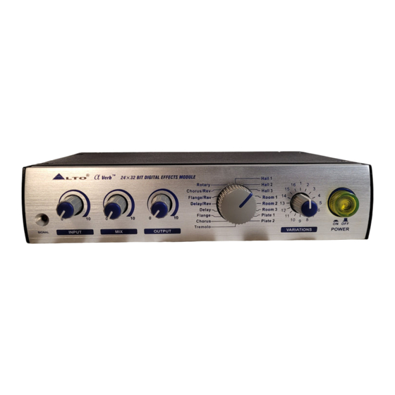
Verb, you purchased a very powerful effect processor, easy to use and contained in a very efficient half rack package. Verb is divided in 16 effects algorithms and 16 variations for each of these algorithms. The variations modify the most important parameter of the current algorithm and, for some algorithm as chorus and flanger, may decide also the shape of the modu- lating signal (Sinusoid or Ramp). -
Page 8: Program And Variations Selections
- Analog Output Level Potentiometer: The output level control sets the level of the output signal going to the amplifier or mixer from Verb. - Dry/Wet Mix Potentiometer: Adjusts the balance between the dry signal coming into the input and the effects generated by Verb. -
Page 9: Power Connector
Turn on the power of the amplifier/mixer, and adjust the volume. 4.2. Analog a. Input Jack Wiring Verb's [LEFT] INPUT jack is also mono input for the Verb. If you only connect a single mono cable to the [LEFT] INPUT jack, it will be also routed auto- matically to the [RIGHT] INPUT. -
Page 10: Levels Setting
4.3 Installation a. Standard Use Verb may be placed almost anywhere: on a table, on top of an amp, next to a mixing console. If it will be on furniture, check the rubber feet provided to the bottom of the unit. Make sure to place the Verb's power supply away from other audio equipment that may induce fields, and away from the signal wiring. - Page 11 VARIATIONS STEREO. Connect two audio cables to the [LEFT] and [RIGHT] INPUTS of Verb from a stereo source, and two other audio cables from the [LEFT] and [ RIGHT] OUTPUTS of the Verb to a stereo amplification system or two mixer inputs.
-
Page 12: Mixer
- MIXER Interfacing to a Mixing Console Verb can accept mono or stereo sends at all system levels. The input circuitry of the Verb can easily accept professional +8/9dBu levels while having enough input and output gain to interface with the low signal levels of home recording systems. - Page 13 Therefore, it is necessary to set the mix so that only effected ("WET") signal is present at the Verb's outputs. To do this, turn the Mix control all the way to the right. Mono in - stereo out.
-
Page 14: Rack Mounting
5. Depending on the input sensitivity of the mixer's channels or Aux Returns, the [OUTPUT] knob of the Verb should be set somewhere between "2:00" and fully clockwise ("5:00"). 6. Turn up the AUX RETURN level until desired level of effect in the mix is re- ached. -
Page 15: Rooms
Hall 2 - This is a warmer hall program with 77ms predelay, and adds depth and character to acoustic instruments. Hall 3 - The third program is a medium bright hall with no predelay, and can be used on rock snares and percussions. b. -
Page 16: Chorus
(two players never keep con- stant their relative pitch distance). Verb's algorithm implements the variable delay and the detuning of it is modulated by an LFO (low frequency oscillator) which causes the detuning to vary. The direct sound and the detuned one are summed analogically on the outputs. -
Page 17: Rotary (Speakers)
mes aligned in counter phase, resulting in a time-varying filtering that has been named 'flanger'. The structure of the flanger is then that of the mix of two rand- omly delayed copies of a signal. Here the detuning process is same as the one of the chorus, added with a "regeneration"... -
Page 18: Combined Effects
Chorus+Reverb - The second multieffects program is a layered stereo chorus and large room reverb. Also that one works great on guitars, synths and electric pianos. 5.5 Effects Summary Table a. Program Chart Verb PROGRAM CHART Verb PROGRAM CHART PROGRAM NAME DESCRIPTION ADJUST CONTROL... - Page 19 ROOM 2 ROOM REVERB Algorithm DECAY TIME Input LP filter: 16 kHz Process High Damp Filter: 14 kHz Process Low Damp Filter: 20 Hz Predelay Time: 0.003 ms Output LP filter: 12 kHz Output HP filter: 20 Hz ROOM 3 ROOM REVERB Algorithm DECAY TIME Input LP filter: 6.5 kHz...
-
Page 20: Preset Value
DELAY/REVERB MONO DELAY + REVERB Algorithm DELAY TIME Input High Damp Filter: 18 kHz DE AY TIME Input Low Damp Filter: 10 Hz Predelay Time: 0.0 ms Process LP filter: 12 kHz FLANGER/REVERB MONO DELAY + FLANGE Algorithm REVERB DECAY TIME Input High Damp Filter: 18 kHz REGENERATION PERCENTAGE Input Low Damp Filter: 10 Hz... - Page 21 Preset encoder Variation encoder Value position position Decay time = 1.46 sec. Decay time = 1.90 sec. Decay time = 2.20 sec. Decay time = 3.50 sec. Decay time = 4.40 sec. Decay time = 9.10 sec. Decay time = > 30 sec. Hall 2 Decay time = 0.39 sec.
- Page 22 Preset encoder Variation encoder Value position position Decay time = 6.40 sec. Decay time = 13.90 sec. Decay time = > 40 sec. Decay time = 0.32 sec. Room 1 Decay time = 0.37 sec. Decay time = 0.43 sec. Decay time = 0.46 sec.
- Page 23 Preset encoder Variation encoder Value position position Decay time = > 25 sec. Room 3 Decay time = 0.35 sec. Decay time = 0.38 sec. Decay time = 0.41 sec. Decay time = 0.47 sec. Decay time = 0.52 sec. Decay time = 0.62 sec.
- Page 24 Preset encoder Variation encoder Value position position Decay time = 0.51 sec. Decay time = 0.56 sec. Decay time = 0.64 sec. Decay time = 0.67 sec. Decay time = 0.81 sec. Decay time = 0.96 sec. Decay time = 1.07 sec. Decay time = 1.39 sec.
- Page 25 Preset encoder Variation encoder Delay Time Delay Decay Time Rev. Decay Time position position Delay+Rev 30 ms 1.30 sec. 40 ms 1.30 sec. 50 ms 1.30 sec. 60 ms 1.40 sec. 80 ms 0.75 sec. 1.30 sec. 100 ms 1.40 sec. 2.30 sec.
- Page 26 Preset encoder Variation encoder Period Rate Amplitude Att. position position 400 ms 2.50 Hz 36 % 320 ms 3.12 Hz 36 % 260 ms 3.84 Hz 36 % 200 ms 5.00 Hz 36 % Preset encoder Variation encoder Period Rate position position Chorus...
- Page 27 Preset encoder Variation encoder Period Rate Feedback % position position 6.05 sec. 0.165 Hz 6.05 sec. 0.165 Hz 4.50 sec. 0.222 Hz 3.00 sec. 0.333 Hz 1.75 sec. 0.571 Hz 1.30 sec. 0.769 Hz 1.00 sec. 1.000 Hz 0.75 sec. 1.333 Hz 0.70 sec.
- Page 28 Preset encoder Variation encoder Flanger Period Flanger Rate Rev. Decay Time position position Flanger + Rev. 2.00 sec. 0.500 Hz 0.80 sec. 2.00 sec. 0.500 Hz 1.30 sec. 2.00 sec. 0.500 Hz 1.75 sec. 2.00 sec. 0.500 Hz 2.20 sec. 2.00 sec.
-
Page 29: Technical Specifications
6. Technical Specifications 6.1 Block Diagram... -
Page 30: Specifications
6.2 Specifications Electrical Frequency Response: +0.5 / -1.5 dB from 20Hz to 20 kHz S/N Ratio (process) 80 dB "A" wtg, 20 Hz-22kHz S/N Ratio (bypass) >90 dB "A" wtg, 20 Hz-22kHz <0.008% @ 1kHz (0dBV, bypass) THD+Noise: Input Number of Channels: Format: 1/4"... - Page 31 Processing and Memory Processor Speed: 12 MIPs (million instructions per second) Internal DSP resolution: 52 bit MPY accumulator Main Preset Programs Preset Total Combinations Internal digital audio memory: 3000 milliseconds Physical 1kg(2.20lb) Net Weight: 200(W) 150(D) 45(H)mm Dimension: (7.87" 5.91" 1.77")
-
Page 32: Warranty
7. Warranty 1. WARRANTY REGISTRATION CARD To obtain Warranty Service, the buyer should first fill out and return the enclosed Warranty Registration Card within 10 days of the Purchase Date. All the information presented in this Warranty Registration Card gives the manufacturer a better understanding of the sales status, so as to purport a more effective and efficient after-sales warranty service. - Page 33 3.5 In no event shall be liable for any incidental or consequential damages. Some states do not allow the exclusion or limitation of incidental or consequential damages, so the above exclusion or limitation may not apply to you. 3.6 This warranty gives you the specific rights, and these rights are compatible with the state laws, you may also have other statutory rights that may vary from state to state.
- Page 34 Tel: 886-4-22313737 email: info@altomobile.com Fax: 886-4-22346757 All rights reserved to ALTO Mobile. Due to continued development in response to customer feedback, product features, specifications and/or internal/external design may be changed without prior notice. No photocopying, translation or reproduction of any part of this user manual is allowed without prior written permission.Copyright...
Need help?
Do you have a question about the Verb and is the answer not in the manual?
Questions and answers