Bunn VLPF Operating & Service Manual
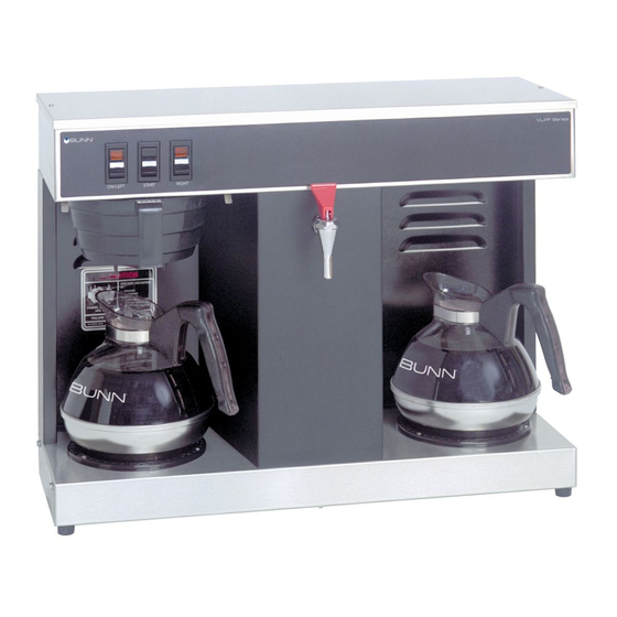
Coffee brewer
Hide thumbs
Also See for VLPF:
- Illustrated parts catalog (18 pages) ,
- Operating & service manual (28 pages)

Related Manuals for Bunn VLPF


Summary of Contents for Bunn VLPF
- Page 1 BUNN ® VLPF OPERATING & SERVICE MANUAL BUNN-O-MATIC CORPORATION POST OFFICE BOX 3227 SPRINGFIELD, ILLINOIS 62708-3227 PHONE: (217) 529-6601 FAX: (217) 529-6644 10179.0000G 6/00 ©1987 BUNN-O-MATIC CORPORATION...
-
Page 2: Table Of Contents
Wiring Diagram ................... 28 WARRANTY Bunn-O-Matic Corp. (“Bunn”) warrants the equipment manufactured by it to be commercially free from defects in material and workmanship existing at the time of manufacture and appearing within one year from the date of installation. In addition: 1.) Bunn warrants electronic circuit and/or control boards to be commercially free from defects in material and... -
Page 3: User Notices
USER NOTICES Carefully read and follow all notices on the equipment and in this manual. They were written for your protection. All notices on the equipment should be kept in good condition. Replace any unreadable or dam- aged labels. #00658.0000 #00656.0000 #00831.0000 #00882.0000... -
Page 4: Electrical, Plumbing Requirements, Operating Controls
25 feet from the 1/2” water supply line. A tight coil of copper tubing in the water line will facilitate moving the brewer to clean the countertop. Bunn-O-Matic does not recommend the use of a saddle valve to install the brewer. -
Page 5: Initial Setup, Brew Volume Adjustments
INITIAL SET-UP CAUTION - The brewer must be unplugged throughout the Initial Set-up , except when specified in the instruc- tions. 1. Remove the top lid from the brewer. 2. Rotate the control thermostat knob fully counterclockwise to the “OFF” position and replace the top lid. 3. -
Page 6: Coffee Brewing, Cleaning
CLEANING 1. The use of a damp cloth rinsed in any mild, non-abrasive, liquid detergent is recommended for cleaning all surfaces on Bunn-O-Matic equipment. 2. Check and clean the sprayhead. The sprayhead holes must always remain open. 3. With the sprayhead removed, insert the deliming spring (provided) all the way into the sprayhead tube. -
Page 7: Troubleshooting
TROUBLESHOOTING A troubleshooting guide is provided to suggest probable causes and remedies for the most likely problems encountered. If the problem remains after exhausting the troubleshooting steps, contact the Bunn-O-Matic Technical Services Department. • Inspection, testing, and repair of electrical equipment should be performed only by qualified service person- nel. - Page 8 TROUBLESHOOTING (cont.) PROBLEM PROBABLE CAUSE REMEDY Equipment will not operate 1. No power or incorrect voltage (A) Plug in brewer. (B) Check wall outlet for 120V ac (C) Check circuit breaker/fuse. Brew cycle will not start 1. No water Check plumbing and shut-off valves.
- Page 9 TROUBLESHOOTING (cont.) PROBLEM PROBABLE CAUSE REMEDY Automatic refill will not operate 2. Liquid level control system Refer to Service - Liquid Level after drawing hot water.(cont.) Control system for testing proce- dures. See page 20. 3. Relay Refer to Service - Relay for test- ing procedures.
- Page 10 TROUBLESHOOTING (cont.) PROBLEM PROBABLE CAUSE REMEDY Decanter warmer is not hot 1. Warmer switches (A) The decanter warmer switch must be in the upper position for the warmer to operate. (B) Refer to Service - On/Left or Right switch for testing proce- dures.
- Page 11 2. Coffee A sufficient quantity of fine or drip grind coffee should be used for proper extraction. 3. Sprayhead Bunn-O-Matic sprayhead #01082.0000 should be used to properly wet the bed of ground coffee in the funnel. 10179 060100...
- Page 12 TROUBLESHOOTING (cont.) PROBLEM PROBABLE CAUSE REMEDY Weak beverage (cont.) 4. Funnel loading The BUNN ® paper filter should be centered in the funnel and the bed of ground coffee leveled by gentle shaking. 5. Water temperature Empty a decanter and place it on the left warmer.
-
Page 13: Service
SERVICE This section provides procedures for testing and replacing various major components used in this brewer should service become necessary. Refer to Troubleshooting for assistance in determining the cause of any problem. COMPONENT ACCESS WARNING - Unplug the brewer before the removal of any panel or the replacement of any component The On/Left switch, Start switch, Right switch, solenoid valve, brew timer, liquid level control com-... -
Page 14: Brew Timer
SERVICE (cont.) BREW TIMER (early models) 6. Disconnect the in-line connectors on the black and white wires from the timer to the wiring harness. 7. With a voltmeter, check the voltage across the black and white wires when the On/Left switch is in the upper position and the Start switch is pressed to the lower position and released. - Page 15 SERVICE (cont.) BREW TIMER (cont.)(late models) 5. With a voltmeter, check the voltage across termi- nals TL1 and TL4 when the “ON/OFF” switch is in theh “ON” position. Connect the brewer to the power source. The indication must be 0 volts. If voltage is as described, proceed to #6.
- Page 16 SERVICE (cont.) BREW TIMER (cont.)(late models) NOTE: Several ounces of water will continue to sy- 1. Modifying brew volumes. To modify a brew vol- phon from the tank after turning the switch “OFF”. ume, first check that the SET/LOCK switch is in the The brewer remembers this volume and will continue “SET”...
-
Page 17: Control Thermostat
SERVICE (cont.) 6. Disconnect the brewer from the power source. CONTROL THERMOSTAT If voltage is present as described, reconnect the blue wire, the control thermostat is operating properly. If voltage is not present as described, replace the con- trol thermostat. Removal and Replacement 1. -
Page 18: Decanter Warmers
SERVICE (cont.) If voltage is present as described, proceed to #6. DECANTER WARMERS If voltage is not present as described, refer to the Wiring Diagram and check the brewer wiring harness. 6. Disconnect the brewer from the power source. 7. Check for continuity across the two terminals on the warmer. -
Page 19: Limit Thermostat
SERVICE (cont.) LIMIT THERMOSTAT If voltage is present as described, reconnect the blue wire and proceed to #4. If voltage is not present as described, refer to the Wiring Diagram and check the brewer wiring harness. 4. Remove the black wire from the limit thermostat. 5. -
Page 20: Liquid Level Control System
SERVICE (cont.) LIQUID LEVEL CONTROL SYSTEM from any metal surface of the brewer. 6. With a voltmeter, check the voltage across termi- nals 1 & 3 when the On/Left switch is in the upper position. Connect the brewer to the power source. The indication must be 120 volts ac after a delay of approximately 5 seconds. - Page 21 SERVICE (cont.) LIQUID LEVEL CONTROL SYSTEM (cont.) Removal and Replacement: 1. Remove all wires from the liquid level control board terminals. 2. Remove the two #8-32 slotted-head screws hold- ing the circuit board to the brewer hood. 3. Install the new circuit board to the hood, making sure that the two lock-washers are in place below the board and above the spacers.
-
Page 22: On/Left Warmer Switch
SERVICE (cont.) ON/LEFT SWITCH If continuity is not present as described, replace the switch. Removal and Replacement: 1. Remove all wires from the switch terminals. 2. Compress the clips inside the hood and gently push the switch through the opening. 3. -
Page 23: Relay
SERVICE (cont.) 7. Check for continuity across terminals 2 & 7 when the On/Left switch is in the upper position only RELAY until the Start switch is pressed to the lower posi- tion and released. Connect the brewer to the power source. -
Page 24: Right Warmer Switch
SERVICE (cont.) RIGHT SWITCH If continuity is present as describe, reconnect the wires, the switch is operating properly. If continuity is not present as described, replace the switch. Removal and Replacement: 1. Remove all wires from the switch terminals. 2. Compress the clips inside the hood and gently push the switch through the opening. -
Page 25: Solenoid Valve
SERVICE (cont.) 5. Check the solenoid valve for coil action. Connect SOLENOID VALVE the brewer to the power source, place the On/Left switch in the upper position, press and release the Start switch. Listen carefully in the vicinity of the solenoid valve for a “clicking” sound as the coil magnet attracts and after the approximate setting on the brew timer dial, repels the plunger. -
Page 26: Start Switch
SERVICE (cont.) START SWITCH If continuity is present as described, reconnect the wires, the switch is operating properly. (It does not matter which terminals the wires are installed on). If continuity is not present as described, replace the switch. Removal and Replacement: 1. -
Page 27: Tank Heater
SERVICE (cont.) NOTE - If the tank heater remains unable to heat, remove and inspect the heater for cracks in the sheath. TANK HEATER Removal and Replacement: 1. Remove the white wire from the tank heater ter- minal and the blue wire from the limit thermostat terminals. -
Page 28: Wiring Diagram
10179 091599 Page 28...
Need help?
Do you have a question about the VLPF and is the answer not in the manual?
Questions and answers