Sign In
Upload
Download
Table of Contents
Contents
Add to my manuals
Delete from my manuals
Share
URL of this page:
HTML Link:
Bookmark this page
Add
Manual will be automatically added to "My Manuals"
Print this page
×
Bookmark added
×
Added to my manuals
Manuals
Brands
LG Manuals
Washer
WD-1247RD
Service manual
LG WD-1247RD Service Manual
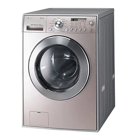
Front-loading washing machine
Hide thumbs
1
2
Table Of Contents
3
4
5
6
7
8
9
10
11
12
13
14
15
16
17
18
19
20
21
22
23
24
25
26
27
28
29
30
31
32
33
34
35
36
37
38
39
40
41
42
43
44
page
of
44
Go
/
44
Contents
Table of Contents
Troubleshooting
Bookmarks
Table of Contents
Service Manual
Washing Machine
Table of Contents
1 Specification
2 Features & Technical Explanation
Water Level Control
Child Lock
Water Circulation
3 Parts Identification
4 Installation
Test Operation
5 Wiring Diagram / Program Chart
6 Operation
7 Trouble Shooting
7-1.Before Svc Checking
7-2.Qc Test Mode
7-3.How to Know the Water Level Frequency
7-4.Error Display
8 Error Diagnosis and Check List
Diagnosis and Answer for Abnormal Operation
Fault Diagnosis and Trouble Shooting
Troubleshooting
No Water Supply
Heating Without Water
9 Disassembly Instructions
Door Lock Switch Assembly
10 Exploded View and Parts List
The Exploded View of Cabinet Assembly
The Exploded View of Drum and Tub Assembly
The Exploded View of Control Panel and Dispenser Assembly
The Exploded View of Dryer
Advertisement
Quick Links
1
Service Manual
2
Washing Machine
3
Specification
4
Parts Identification
5
Operation
6
Trouble Shooting
Download this manual
WASHING MACHINE
SERVICE MANUAL
CAUTION
READ THIS MANUAL CAREFULLY TO DIAGNOSE TROUBLES
CORRECTLY BEFORE OFFERING SERVICE.
MODEL : WD-1247RD / WD-1248RD
Table of
Contents
Previous
Page
Next
Page
1
2
3
4
5
Advertisement
Table of Contents
Troubleshooting
TROUBLE SHOOTING
15
FAULT DIAGNOSIS AND TROUBLE SHOOTING
21
Need help?
Do you have a question about the WD-1247RD and is the answer not in the manual?
Ask a question
Questions and answers
Related Manuals for LG WD-1247RD
Washer LG WD-803(4)0(W)(F)(H) Service Manual
Front-loading washing machine (50 pages)
Washer LG WD-1248 SERIES Serveice Manual
(34 pages)
Washer LG WD-12440 Owner's Manual
(31 pages)
Washer LG WD-12436RD Owner's Manual
(56 pages)
Washer LG WD-14440 Owner's Manual
(31 pages)
Washer LG WD-1248RD Service Manual
Front-loading washing machine (44 pages)
Washer LG WD-12480S Service Manual
(35 pages)
Washer LG WD-12480S Service Manual
(35 pages)
Washer LG WD-12480N Service Manual
(35 pages)
Washer LG WD-12440(5)FDS Owner's Manual
Front-loading washing machine (59 pages)
Washer LG WD-12470BD Owner's Manual
(60 pages)
Washer LG WD-1249(0~9)SP/NP/TP Owner's Manual
(21 pages)
Washer LG WD-10480 Serveice Manual
(34 pages)
Washer LG WD1249 FD Series Service Manual
(44 pages)
Washer LG WD-1244RDS Owner's Manual
(35 pages)
Washer LG WD-1243RHD Owner's Manual
(28 pages)
This manual is also suitable for:
Wd-1248rd
Wd-12475rd
Wd-12470rd
Wd-12476rd
Wd-12477rd
Wd-12478rd
...
Show all
Wd-12479rd
Wd-12tfl
Wd-12tfp
Wd-1247 series
Table of Contents
Print
Rename the bookmark
Delete bookmark?
Delete from my manuals?
Login
Sign In
OR
Sign in with Facebook
Sign in with Google
Upload manual
Upload from disk
Upload from URL


Need help?
Do you have a question about the WD-1247RD and is the answer not in the manual?
Questions and answers