Table of Contents
Advertisement
www.nordictrack.com
Model No. NTL79011.0
Serial No.
Write the serial number in the space
USER’'S MANUAL
above for reference.
Serial Number
Decal
QUESTIONS?
If you have questions, or if parts
are damaged or missing, DO NOT
CONTACT THE STORE; please
contact Customer Care.
IMPORTANT: Please register this
product (see the limited warranty
on the back cover of this manual)
before contacting Customer Care.
CALL TOLL-FREE:
1-800-TO-BE-FIT
(1-800-862-3348)
Mon.––Fri. 6 a.m.––6 p.m. MT
Sat. 8 a.m.––4 p.m. MT
ON THE WEB:
www.nordictrackservice.com
CAUTION
Read all precautions and instruc-
tions in this manual before using
this equipment. Keep this manual
for future reference.
Advertisement
Table of Contents

Related Manuals for NordicTrack NTL79011.0


Summary of Contents for NordicTrack NTL79011.0
- Page 1 Model No. NTL79011.0 Serial No. Write the serial number in the space USER’’S MANUAL above for reference. Serial Number Decal QUESTIONS? If you have questions, or if parts are damaged or missing, DO NOT CONTACT THE STORE; please contact Customer Care.
-
Page 2: Table Of Contents
TABLE OF CONTENTS WARNING DECAL PLACEMENT ............. . 2 IMPORTANT PRECAUTIONS . -
Page 3: Important Precautions
IMPORTANT PRECAUTIONS WARNING: To reduce the risk of serious injury, read all important precautions and instructions in this manual and all warnings on your treadmill before using your treadmill. ICON assumes no responsibility for personal injury or property damage sustained by or through the use of this product. - Page 4 20. Never leave the treadmill unattended while DANGER : Always unplug the power it is running. Always remove the key, unplug cord immediately after use, before clean- the power cord, and press the power switch ing the treadmill, and before performing the into the off position when the treadmill is not maintenance and adjustment procedures in use.
-
Page 5: Before You Begin
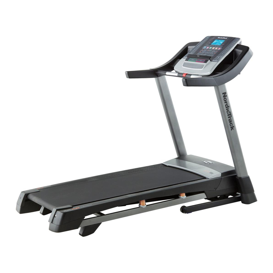
BEFORE YOU BEGIN Thank you for selecting the new NORDICTRACK ® T7.0 manual. To help us assist you, note the product model treadmill. The T7.0 treadmill provides an impressive number and serial number before contacting us. The selection of features designed to make your workouts model number and the location of the serial number at home more effective and enjoyable. -
Page 6: Part Identification Chart
PART IDENTIFICATION CHART Use the drawings below to identify small parts used for assembly. The number in parentheses below each draw- ing is the key number of the part, from the PART LIST near the end of this manual. The number following the key number is the quantity used for assembly. -
Page 7: Assembly
ASSEMBLY •• Assembly requires two persons. •• Assembly requires the following tools: the included hex keys •• Place all parts in a cleared area and remove the packing materials. Do not dispose of the packing one adjustable wrench materials until you nish all assembly steps. one Phillips screwdriver ••... - Page 8 3. Identify the Left Upright (84), which is marked ““Left.”” Have a second person hold the Left Upright near the Base (29). See the inset drawing. Tie the wire tie in the Left Upright (84) securely around the end of the Upright Wire (91).
- Page 9 5. Hold the Right Upright (85) against the Base (29). Partially tighten three 3/8" x 4" Screws (3) with three 3/8" Star Washers (10) into the Right Upright and Base; do not fully tighten the Screws yet. 6. Identify the Left and Right Base Covers (88, 89), which are marked ““Left””...
- Page 10 7. Identify the Left Handrail (79), which is marked ““Left.”” If there is a wire in the Left Handrail, re- move and discard it. Hold the Left Handrail (79) near the Left Upright (84). Insert the wire tie on the Upright Wire (91) into the bottom and out of the end of the Left Handrail as shown.
- Page 11 9. Set the Console Base (98) face down on a soft surface to avoid scratching the Console Base. Remove the two screws (A) from the Pulse Crossbar (81). Remove the Pulse Crossbar and discard the screws. Remove the four 5/16" x 5/8" Screws (11) from the Console Frame (101).
- Page 12 11. IMPORTANT: To avoid damaging the Pulse Crossbar (81), do not use power tools and do not overtighten the #10 x 3/4" Screws (4). Orient the Pulse Crossbar (81) as shown. Attach the Pulse Crossbar to the Left and Right Handrails (79, 83) with four #10 x 3/4"...
- Page 13 13. Set the console assembly on the Left and Right Console Handrails (79, 83). Make sure that no wires Assembly are pinched. Insert the excess Upright Wire (91) behind the Console Frame (101). Attach the console assembly to the brackets on the Handrails (79, 83) with the four 5/16"...
- Page 14 16. Raise the Frame (57) to the position shown. Have a second person hold the Frame until this step is completed. Orient the Storage Latch (54) so that the large barrel and the latch knob are oriented as shown. Remove any ties from the end of the Storage Latch (54).
-
Page 15: Operation And Adjustment
OPERATION AND ADJUSTMENT HOW TO CONNECT THE POWER CORD nominal 120-volt circuit capable of carrying 15 or more amps. To avoid overloading the circuit, do Use a Surge Suppressor not plug other electrical devices, except for low- power devices such as cell phone chargers, into Your treadmill, like other electronic equipment, can be the surge suppressor or into an outlet on the same damaged by sudden voltage changes in your home’’s... - Page 16 CONSOLE DIAGRAM FEATURES OF THE CONSOLE You can even listen to your favorite workout music or The treadmill console offers an impressive array of audio books with the console’’s stereo sound system features designed to make your workouts more effec- while you exercise.
- Page 17 HOW TO TURN ON THE POWER HOW TO USE THE MANUAL MODE IMPORTANT: If the treadmill has been exposed to 1. Insert the key into the console. cold temperatures, allow it to warm to room tem- perature before turning on the power. If you do not See HOW TO TURN ON THE POWER at the left.
- Page 18 4. Change the incline of the treadmill as desired. The My Trail tab will show a track that represents 1/4 mile (400 m). As you exercise, the white rect- To change the incline of the treadmill, press the angle will show your progress. The My Trail tab will Incline increase or decrease button or one of the also show the number of laps you complete.
- Page 19 6. Measure your heart rate if desired. Press the Manual fan button repeatedly to Before using select a fan speed or to the handgrip turn off the fan. Press heart rate moni- the Auto fan button to tor, remove the select the auto mode or to turn off the fan.
- Page 20 HOW TO USE AN ONBOARD WORKOUT During the workout, the 1. Insert the key into the console. pro les on the speed and See HOW TO TURN ON THE POWER on page 17. incline tabs Current Segment will show your 2.
- Page 21 If the speed or incline setting is too high or too low HOW TO USE AN IFIT LIVE WORKOUT at any time during the workout, you can manu- ally override the setting by pressing the Speed or Note: To use an iFit Live workout, you must have an Incline buttons;...
- Page 22 When you select an iFit Live workout, the display 7. Measure your heart rate if desired. will show the duration of the workout, the distance you will walk or run, and the approximate number of See step 6 on page 19. calories you will burn.
- Page 23 THE INFORMATION MODE 3. CONTRAST LVL: Press the Incline increase and decrease buttons to adjust the contrast level of the The console features an information mode that keeps display. track of treadmill information and allows you to person- alize console settings. If a module is connected, you may also select the following screen: To select the information mode, hold down the Stop...
-
Page 24: How To Fold And Move The Treadmill
HOW TO FOLD AND MOVE THE TREADMILL HOW TO FOLD THE TREADMILL HOW TO MOVE THE TREADMILL To avoid damaging the treadmill, adjust the incline Before moving the treadmill, fold it as described at the to the lowest position before you fold the treadmill. left. -
Page 25: Troubleshooting
TROUBLESHOOTING Most treadmill problems can be solved by following c. Remove the key from the console, and then the simple steps below. Find the symptom that reinsert it. applies, and follow the steps listed. If further assis- tance is needed, see the front cover of this manual. d. - Page 26 Locate the Reed Switch (52) and the Magnet (51) b. If the walking belt is overtightened, treadmill per- on the left side of the Pulley (50). Turn the Pulley formance may decrease and the walking belt may until the Magnet is aligned with the Reed Switch. become damaged.
- Page 27 SYMPTOM: The walking belt is off-center or slips b. If the walking belt slips when walked on, rst re- when walked on move the key and UNPLUG THE POWER CORD. Using the hex key, turn both idler roller screws a.
-
Page 28: Exercise Guidelines
EXERCISE GUIDELINES Burning Fat——To burn fat effectively, you must exer- WARNING: cise at a low intensity level for a sustained period of Before beginning this time. During the first few minutes of exercise, your or any exercise program, consult your physi- body uses carbohydrate calories for energy. - Page 29 SUGGESTED STRETCHES The correct form for several basic stretches is shown at the right. Move slowly as you stretch ——never bounce. 1. Toe Touch Stretch Stand with your knees bent slightly and slowly bend forward from your hips. Allow your back and shoulders to relax as you reach down toward your toes as far as possible.
-
Page 30: Part List
PART LIST Model No. NTL79011.0 R0612A Key No. Qty. Description Key No. Qty. Description #8 x 1/2" Screw Magnet 3/8" x 2" Bolt Reed Switch 3/8" x 4" Screw Cable Tie #10 x 3/4" Screw Storage Latch #10 Star Washer Drive Motor #8 x 1/2"... - Page 31 Key No. Qty. Description Key No. Qty. Description Console Frame –– User’’s Manual Console Clamp Note: Speci cations are subject to change without notice. For information about ordering replacement parts, see the back cover of this manual. *These parts are not illustrated.
-
Page 32: Exploded Drawing
EXPLODED DRAWING A Model No. NTL79011.0 R0612A... - Page 33 EXPLODED DRAWING B Model No. NTL79011.0 R0612A...
- Page 34 EXPLODED DRAWING C Model No. NTL79011.0 R0612A...
- Page 35 EXPLODED DRAWING D Model No. NTL79011.0 R0612A...
-
Page 36: Ordering Replacement Parts
ORDERING REPLACEMENT PARTS To order replacement parts, please see the front cover of this manual. To help us assist you, be prepared to provide the following information when contacting us: •• the model number and serial number of the product (see the front cover of this manual) ••...
Need help?
Do you have a question about the NTL79011.0 and is the answer not in the manual?
Questions and answers