Table of Contents
Advertisement
PORTABLE
FORCED AIR HEATERS
"USER'S MANUAL"
LISTED
Pro
MODEL : RMC-KFA70TDGP,
RMC-KFA125TDGP
RMC-KFA170TDGP
Before the first use of this heater, please read this USER'S MANUAL very
carefully. This USER'S MANUAL has been designed to instruct you as to
the proper manner in which to assemble, maintain, store, and most
importantly, how to operate the heater in a safe and efficient manner.
Please keep this manual for future reference.
CFM Corporation, Mississauga, ON L5N 8A3
CFM U.S. Corporation, Huntington, IN 46750
Phone: 1-800-668-5323
Advertisement
Table of Contents

Related Manuals for Dyna-Glo RMC-KFA70TDGP


Summary of Contents for Dyna-Glo RMC-KFA70TDGP
- Page 1 PORTABLE FORCED AIR HEATERS “USER’S MANUAL” LISTED MODEL : RMC-KFA70TDGP, RMC-KFA125TDGP RMC-KFA170TDGP Before the first use of this heater, please read this USER’S MANUAL very carefully. This USER’S MANUAL has been designed to instruct you as to the proper manner in which to assemble, maintain, store, and most importantly, how to operate the heater in a safe and efficient manner.
-
Page 2: Risk Of Electric Shock
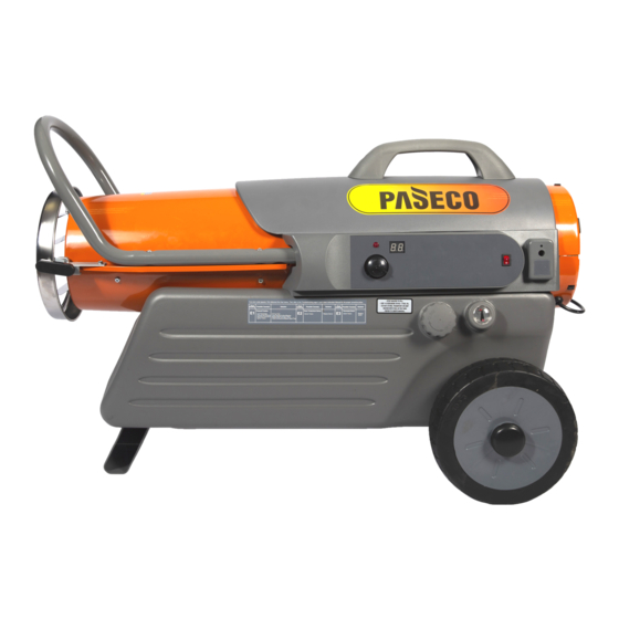
NEVER LEAVE THE HEATER UNATTENDED WHILE BURNING! DANGER - IMPROPER USE OF THIS HEATER CAN RESULT IN SERIOUS INJURY OR DEATH FROM BURNS, FIRE, EXPLOSION, ELECTRICAL SHOCK AND/OR CARBON MONOXIDE POISONING. WARNINGS: 1. RISK OF INDOOR AIR POLLUTION! • Use this heater only in well ventilated areas. Provide at least a three-square foot (2,800 sq. cm.) opening of fresh outside air for each 100,000 BTU/hr. - Page 3 2. FEATURES Hot Air Outlet Front Guard Handle Upper Shell Cord Wrap Lower Shell Fuel Cap Fan Guard Fuel Gauge Pressure Gauge Indicator Lamp Fuel Tank Thermostat Knob Dual Source LED Power/Reset Power Cord Switch Figure 1. RMC-KFA70TDGP...
- Page 4 NEVER LEAVE THE HEATER UNATTENDED WHILE BURNING! Front Handle Hot Air Outlet Handle Louver Cord Wrap Upper Shell Lower Shell Indicator Lamp Fan Guard Thermostat Knob Pressure Gauge Room Temp. Display Dual Source Power Cord Fuel Cap Fuel Tank Fuel Gauge Figure 2.
-
Page 5: Unpacking And Assembly
Louver Hardware Kit : HW-KFA1001 Hardware Kit : HW-KFA1008 Screws Handle Cord Wrap Hardware Kit Part No : HW-KFA1001 Figure 4. RMC-KFA70TDGP MODEL Screws (A) Screws (B) Washers Bushings Cotter Pins Wheels Cord Wrap Hardware Kit Part No : HW-KFA1008... - Page 6 NEVER LEAVE THE HEATER UNATTENDED WHILE BURNING! 2. ASSEMBLY A. For RMC-KFA70TDGP Model only (See Figure 6,7) Screw Front Guard Tools Required Handle • Medium Phillips Screwdriver Hot Air Outlet 1. Assembling Handle. 1) Lift front guard for arrow direction and make sure that Boss guard’s wedged portion fits into the slit hole in the...
- Page 7 NEVER LEAVE THE HEATER UNATTENDED WHILE BURNING! Front Handle Screw(A) Screw(B) Screw Handle Louver Screw(B) Cord Wrap Wheel Flat Washer Wheel Cap Bushing Extended Hub Wheel Axle Cotter Pin Figure 8. Wheel and Handle Assembly, RMC-KFA125TDGP/RMC-KFA170TDGP Models Only. NOTE : Heater should be inspected before each use, and at least annually by a qualitied service person. 4.
-
Page 8: Fueling Your Heater
194˚F/90˚C RMC-KFA125TDGP 122˚F/50˚C 104˚F/40˚C RMC-KFA70TDGP 158˚F/70˚C 104˚F/40˚C Once the temperature falls below the reset temperature you will be able to start your heater. B. Electrical System Protection : The heaters electrical system is protected by a circuit breaker mounted to the power switch that protects the PCB assembly and other electrical components from damage. - Page 9 NEVER LEAVE THE HEATER UNATTENDED WHILE BURNING! 7. OPERATION A.) VENTILATION RISK OF INDOOR AIR POLLUTION/USE HEATER ONLY IN WELL VENTILATED AREAS. Provide a fresh air opening of at least three square feet (2,800 sq. cm) for each 100,000 BTU/Hr. rating.
-
Page 10: Long Term Storage Of Your Heater
NEVER LEAVE THE HEATER UNATTENDED WHILE BURNING! EXTRA ELECTRIC OUTLET WARRING : SHOCK HAZARD - Always cover Electric Outlet When not in use - Don’t Plug and use a appliance more than 5A current in this Outlet. Electric Outlet Cover C.) LOUVER Figure 10. -
Page 11: Maintenance
Screw using medium phillips screwdriver. These Electric Outlet Screws attach Upper Rear and Lower shells together. (See Figure 14) (RMC-KFA70TDGP Model Only.) Figure 14. Upper Shell Removal. -Remove Screws along each side of heater using medium phillips screwdriver. These Screws attach Upper and Lower shells together. - Page 12 NEVER LEAVE THE HEATER UNATTENDED WHILE BURNING! D.) FAN BLADES CLEAN EVERY SEASON OR AS NEEDED. Set Screw -Remove upper shell(See 10 page.) Set Screw -Use 1/8" allen wrench to loosen set screw Motor Shaft which holds Fan Blade to motor shaft. - Slip Fan Blade off motor shaft.
- Page 13 NEVER LEAVE THE HEATER UNATTENDED WHILE BURNING! F.) SPARK PLUG CLEAN AND REGAP EVERY 600 HOURS 0.140"Gap Spark Plug OF OPERATION OR REPLACE AS NEEDED. -Remove upper shell(See 10 page). -Remove Fan Blade(See 11 Page). -Remove Ignitor Wire from Spark Plug. -Remove Spark Plug from Burner Head using medium phillips screwdriver.
-
Page 14: Pump Pressure Adjustment
Turn Relief Valve clockwise to increase pressure. Turn Relief Valve counter-clockwise to decrease pressure. Set Pump pressure according to the chart below. -Stop Heater(See Operation, Page 8). MODEL PUMP PRESSURE RMC-KFA70TDGP 3.7 psi RMC-KFA125TDGP 5.5 psi Pressure Gauge RMC-KFA170TDGP 6.5 psi Figure 21. -
Page 15: Replacing Fuse
NEVER LEAVE THE HEATER UNATTENDED WHILE BURNING! 10. REPLACING FUSE NOTICE : This heater is fuse protected. If your heater fails to ignite, DO NOT RETURN YOUR HEATER TO THE STORE. Please follow the simple instruction below to inspect and change the fuse. PROCEDURE FOR REPLACING FUSE WARNING : SHOCK HAZARD To prevent personal injury, unplug the power cord before replacing fuse. -
Page 16: Troubleshooting Guide
NEVER LEAVE THE HEATER UNATTENDED WHILE BURNING! 11. TROUBLE SHOOTING GUIDE TORUBLE POSSIBLE CAUSE CORRECTIVE ACTION Heater ignites but MAIN PCB 1. Wrong pump pressure 1. See Pump Pressure Adjustment, assembly shuts heater off after Page 13. a short period of time. 2. -
Page 17: Wiring Diagram
NEVER LEAVE THE HEATER UNATTENDED WHILE BURNING! 12. WIRING DIAGRAM A) WIRING DIAGRAM(RMC-KFA70TDGP) CONTROL PCB BLACK SPARK PLUG BLACK IGNITOR WHITE POWER LAMP BLACK (LED) ORANGE BLACK MT-ORG PUMP WHITE MOTOR MT-RED CAPACITOR GREEN 12uF/230VAC THERMOSTAT CN2(AC2)/ (TEMP. CONTROL) EARTH... -
Page 18: Specifications
NEVER LEAVE THE HEATER UNATTENDED WHILE BURNING! 13. SPECIFICATIONS 16.8" 14.5" 27.8" RMC-KFA70TDGP KFA125TDGP KFA170TDGP 27" 27" 32.1" 36.9" 18.5" 18.5" RMC-KFA125TDGP / RMC-KFA170TDGP MODEL RMC-KFA70TDGP RMC-KFA125TDGP RMC-KFA170TDGP BTU/Hr. 70,000 125,000 170,000 Fuel Consumption - Gal./Hr. 0.53 0.95 Fuel Tank Capacity - Gal. -
Page 19: Exploded Parts
NEVER LEAVE THE HEATER UNATTENDED WHILE BURNING! 14. EXPLODED PARTS DRAWING(RMC-KFA70TDGP Model Only) Burner Head Assembly 21-4 21-11 21-5 21-10 21-6 21-7 21-8 21-9 21-1 21-2 21-3 19 20 32-2 32-1 Motor Pump Assembly 23-2 23-5 23-6 23-7 23-9 23-8... - Page 20 NEVER LEAVE THE HEATER UNATTENDED WHILE BURNING! 15. PARTS LIST(RMC-KFA70TDGP Model Only) KEY NO. DESCRIPTION PART NO. KEY NO. DESCRIPTION PART NO. Motor Supportor 2151-0016-00 Fuel Tank Assembly 23-3 3121-0358-00 Fuel Gauge 2156-0023-00 4331-0013-00 23-4 Pump Body Fuel Gauge Cap...
- Page 21 NEVER LEAVE THE HEATER UNATTENDED WHILE BURNING! 15. EXPLODED PARTS DRAWING(RMC-KFA125T/170TDGP Models Only) Burner Head Assembly 21-4 21-11 21-5 21-6 21-10 21-9 21-7 21-8 21-1 21-2 21-3 33-2 33-1 Motor Pump Assembly 23-2 23-5 23-6 23-7 23-9 23-8 23-1 23-10 23-15 23-3 23-16...
- Page 22 NEVER LEAVE THE HEATER UNATTENDED WHILE BURNING! 17. PARTS LIST(RMC-KFA125T/170TDGP Models Only) PART NO. KEY NO. DESCRIPTION RMC-KFA125TDGP RMC-KFA170TDGP Fuel Tank Assembly 2151-0012-00 2151-0011-00 2156-0022-00 2156-0022-00 Fuel Gauge 3231-0123-00 3231-0123-00 Fuel Gauge Cap 3231-0122-00 3231-0122-00 Fuel Cap 2155-0010-00 2155-0010-00 Fuel Filter Assembly Shell Lower Assembly 2151-0014-01 2151-0013-01...
- Page 23 NEVER LEAVE THE HEATER UNATTENDED WHILE BURNING! PART NO. KEY NO. DESCRIPTION RMC-KFA125TDGP RMC-KFA170TDGP Rotor Kit SP-KFA1000 SP-KFA1000 23-8 Blade See SP-KFA1000 See SP-KFA1000 23-9 3531-0008-00 3531-0008-00 End Pump Cover 23-10 Elbow 3231-0093-00 3231-0093-00 23-11 Flange Bolt 4329-0014-00 4329-0014-00 23-12 See SP-KFA1005 See SP-KFA1005 Lint Filter...
-
Page 24: Parts List (Wheels And Handle)
NEVER LEAVE THE HEATER UNATTENDED WHILE BURNING! 18. PARTS LIST (WHEELS AND HANDLE) RMC-KFA70TDGP MODEL PART NO. DESCRIPTION RMC-KFA70TDGP Handle 3231-0125-00 Cord Wrap 3231-0056-00 Hardware Kit HW-KFA1001 2) RMC-KFA125T/170TDGP MODELS PART NO. KEY NO. DESCRIPTION RMC-KFA125TDGP RMC-KFA170TDGP Handle Front 3551-0039-00...
Need help?
Do you have a question about the RMC-KFA70TDGP and is the answer not in the manual?
Questions and answers