Minolta CF2002 Service Manual
Cf2002; cf3102
Hide thumbs
Also See for CF2002:
- Service manual (298 pages) ,
- User manual (162 pages) ,
- Operation manual (132 pages)
Table of Contents

Related Manuals for Minolta CF2002


Summary of Contents for Minolta CF2002
-
Page 1: Service Manual
Service Manual CF2002/CF3102 Printer This Service Manual contains information on the model CF3102/2002 printer as it is converted from the CF3102/2002 copier. Please therefore also use the Service Manual for the CF3102/2002 copier. - Page 2 SAFETY PRECAUTIONS FOR INSPECTION AND SERVICE • When performing inspection and service procedures, observe the following precautions to prevent accidents and ensure utmost safety. ✽ Depending on the model, some of the precautions given in the following do not apply. •...
- Page 3 WARNING 3. Do not throw toner or the toner bottle into a fire. • Do not throw toner or the Toner Bottle (Imaging Cartridge, Toner Cartridge) into a fire. Toner expelled from the fire may cause burns. 4. Use the specified parts. •...
- Page 4 WARNING 9. Maintain a grounded connection at all times. • Connect the power cord to an electrical outlet that is equipped with a grounding terminal. 10. Do not remodel the product. • Modifying this product in a manner not authorized by the manufacturer may result in a fire or electric shock.
- Page 5 CAUTION 2. Precautions for Servicing with Covers and Parts Removed. • Wherever feasible, keep all parts and covers mounted when energizing the product. • If energizing the product with a cover removed is absolutely unavoidable, do not touch any exposed live parts and use care not to allow your clothing to be caught in the moving parts.
-
Page 6: Used Batteries Precautions
1-3. Used Batteries Precautions ALL Areas CAUTION Danger of explosion if battery is incorrectly replaced. Replace only with the same or equivalent type recommended by the manufacturer. Dispose of used batteries according to the manufacturer’s instructions. Germany VORSICHT! Explosionsgefahr bei unsachgemäßem Austausch der Batterie. Ersatz nur durch denselben oder einen vom Hersteller empfohlenen gleichwertigen Typ. -
Page 7: Other Precautions
1-4. Other Precautions • When handling circuit boards, observe the “HANDLING of PWBs”. • The PC Drum is a very delicate component. Observe the precautions given in “HAN- DLING OF THE PC DRUM” because mishandling may result in serious image problems. •... - Page 8 4. Precautions for Dis/Reassembly • Be sure to unplug the copier from the outlet before attempting to service the copier. • The basic rule is not to operate the copier anytime during disassembly. If it is absolutely necessary to run the copier with its covers removed, use care not to allow your clothing to be caught in revolving parts such as the timing belt and gears.
- Page 9 8. Handling of the PC Drum ✽ Only for Products Not Employing an Imaging Cartridge. During Transportation/Storage • Use the specified carton whenever moving or storing the PC Drum. • The storage temperature is in the range between –20°C and +40°C. •...
- Page 10 C. Soak a small amount of either ethyl alcohol or iso- propyl alcohol into a clean, unused Dust-Free Cot- ton Pad which has been folded over into quarters. Now, wipe the surface of the PC Drum in one con- tinuous movement from its rear edge to its front edge and off its surface one to two times.
- Page 12 INDEX GENERAL DIS/REASSEMBLY, ADJUSTMENT SWITCHES ON PWBs, TECH. REP. SETTINGS TROUBLESHOOTING...
-
Page 14: Table Of Contents
CONTENTS GENERAL 1. SPECIFICATION ..................... G-1 2. PRECAUTIONS FOR INSTALLATION ............G-3 2-1. Installation Site ..................G-3 2-2. Power Source ..................G-3 2-3. Grounding ....................G-3 3. PRECAUTIONS FOR USE ................G-4 3-1. To ensure that the copier is used in an optimum condition ..... G-4 3-2. - Page 15 4-1. Calling the Tech. Rep. Mode to Screen ........... S-18 4-2. Tech. Rep. Mode Function Tree .............. S-19 4-3. Setting in the Tech. Rep. Mode ............... S-22 5. SECURITY MODE ................... S-40 5-1. Security Mode Function Setting Procedure ..........S-40 5-2.
-
Page 16: General
GENERAL... -
Page 18: Specification
SPECIFICATION Type Freestanding printer OPC (organic photoconductor) PC Drum Type Electrostatic dry-powdered image transfer to plain Copying System paper Equivalent to 600 dpi in main scanning direction x Print Density 1800 dpi in sub-scanning direction Three-Way system Paper Feeding System Manual Bypass Table...Single (Standard) 1st Drawer....250 sheets... - Page 19 Warming-up Time : 5 min. or less (at ambient temperature of 20 °C, and rated source voltage) 68 ° F First Print Time 31-ppm Printer 20-ppm Printer Full Color 9.9 sec. 14.1 sec. Mono Color 7.9 sec. 7.9 sec. (1st Drawer, full size, LetterC, Manual Exposure) Printing Speed for Multi-Print Cycle (prints/min.) 31-ppm 20-ppm...
-
Page 20: Precautions For Installation
PRECAUTIONS FOR INSTALLATION 2-1. Installation Site To ensure safety and utmost performance of the printer, the printer should NOT be used in a place: • Where it will be subjected to extremely high or low temperature or humidity. • Where it will be subjected to sudden fluctuations in either temperature or humidity. •... -
Page 21: Precautions For Use
PRECAUTIONS FOR USE 3-1. To ensure that the printer is used in an optimum condition • Never place a heavy object on the printer or subject the printer to shocks. • Insert the power plug all the way into the outlet. •... -
Page 22: Handling Of Consumables
HANDLING OF CONSUMABLES Before using any consumables, always read the label on its container carefully. • Paper can be easily damaged by dampness. To prevent absorption of moisture, store paper, which has been removed from its wrapper but not loaded in the drawer, in a sealed plastic bag in a cool, dark place. -
Page 23: System Options
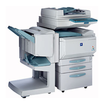
SYSTEM OPTIONS C4581O006AA 4025G001AA C4581O007AA 1. CF3102/CF2002 Printer 12. Hard Disk Drive HDD-5* 2. Duplex Unit AD-14 13. Punch Kit PK-4* 3. Large Capacity Cabinet PF-121 14. Mechanical Counter* 4. Copy Desk CD-2M *:The internal options are not shown. 5. Finisher FN-116 6. -
Page 24: Dis/Reassembly, Adjustment
DIS/REASSEMBLY, ADJUSTMENT... -
Page 26: Service Jig
Name Description Remark Allows settings, adjustments, Supplied from External panel Controller *1 and checks to be made for the Minolta printer using a PC. Starts the External Panel Con- Commercially Notebook PC troller for adjustment. available product Connects between the Note-... -
Page 27: Setting Up The Service Jig
1-2. Setting up the Service Jig NOTE • Before attempting to set, adjust, or check the printer, set up the Service Jig by following the procedure given below. • Do not turn on any equipment until you are instructed to do so. 1. - Page 28 5. Using a cross-cable, connect port A of the selec- tor to the printer. C4581U027AA 6. Make sure that the selector knob is set to “A.” 4004D270AA 7. Turn on your PC and click the External Panel Controller icon. 8. Make sure that the Startup dialog box has appeared.
- Page 29 10. Check that the initial startup screen of the External Panel Controller has appeared on the PC. NOTE • If the basic screen does not appear in the External Panel Controller, turn the printer off. Restart the External Panel Controller, and then turn the printer on again. Initial Startup Screen 4581D010AA 11.
-
Page 30: Electrical/Image Adjustment
ELECTRICAL/IMAGE ADJUSTMENT NOTE • Given in the following are only those adjustments that are made using the External Panel Controller. 2-1. Calling the Tech. Rep. Mode to Screen 1. Set up the Service Jig. ☞ See “Setting up the Service Jig.” (D-2) 2. -
Page 31: X-Rite Calibration (Gradation Adjust
X-Rite Calibration (Gradation Adjust) 1. Set up the Service Jig. ☞ See “Setting up the Service Jig.” (D-2) 2. Call the Tech. Rep. mode to the screen. ☞ See “Calling the Tech. Rep. Mode to Screen.” (D-5) 3. Click the X-Rite Calibration key in the Tech. Rep. Mode screen. - Page 32 6. Check that the dialog box appears, and then click the OK key in the dialog box. NOTE • If the selector is being used, set the selector knob to “B.” C4004P570CA 4004D271AA 7. Check that the dialog box appears, and then click the Yes key in the dialog box.
- Page 33 9. Insert the auto-cal strip into the X-Rite. NOTE • Insert the auto-cal strip after “INSERT CAL STRIP” appears on the X-Rite display. 4004D289AA 4004D272CA 10. If the reading was completed correctly, the dialog box shown at the left appears. Prepare the cyan test pattern.
- Page 34 13. If the reading was completed correctly, “OK” is indicated. C4004P578CA 14. Turn the test pattern around, and then feed it to read the row indicated by “B” in direction “2.” 15. If the reading was completed correctly, a second “OK”...
- Page 35 21. Check that “>>” appears beside “Read the Pat- tern of Magenta.” NOTE • From here on, read the test patterns of magenta, yellow, and black, in that order. • If “>>” appears beside “Read the Pattern of Cyan”, perform the procedure for reading the cyan test pattern again.
-
Page 36: Downloading Firmware
2-3. Downloading Firmware • Firmware is upgraded by means of the memory card (IC card). NOTE • The External Panel Controller is used on the PC to upgrade firmware. • NEVER remove or insert the memory card with the printer power turned ON. 1. - Page 37 8. When downloading is started, a checksum and results are displayed on the dialog box. 4581D014BA 9. Confirm the contents of the display. Then, click “OK” on the “Firmware Download” dia- log box and quit the External Panel Controller. 10. Unplug the power cord from the power outlet. NOTE •...
-
Page 38: Remounting Ram Ic (Ic202
2-4. REMOUNTING RAM IC (IC202) 1. Remove the Image Control Board (PWB-F) from the printer. 2. Demount RAM IC (IC202) from the old Image Control Board (PWB-F). 3. Demount RAM IC (IC202) from the new Image Control Board (PWB-F) and then remount the old RAM IC (IC202) on the new Image Control Board (PWB-F). -
Page 40: Switches On Pwbs, Tech. Rep. Settings
SWITCHES ON PWBs, TECH. REP. SETTINGS... -
Page 42: Printer Panel 1
Printer Panel 1 1-1. Identification and Functions of Keys on Printer Panel 1 C4004O583CA Part Name Description • Off when the printer controller is off or starting up. • Lights up in green to indicate that the printer is ready. Ready light •... -
Page 43: Functions Menu
1-2. Functions menu Functions Menu Setting Procedures 1. Check that “Info XXXX” appears in the display, and then press the Menu key in the printer panel 1. NOTE • “XXXX” indicates the name specified when the controller was set up. (For more details, refer to the manual of the printer controller.) 2. -
Page 44: Functions Menu List
Functions Menu List Functions menu Submenu PS Test Page Configuration Job Log Control Panel Map Color Charts Print Pages PS Font List PCL Font List E-mail Log*1 Total Counter Unit Check Suspend Printing Resume Printing Restart Server Shut Down Shut Down System Reboot System This command is used to run the diagnostic function. -
Page 45: Details Of Engine Setup Settings
Details of Engine Setup Settings Item Purpose Setting/Precautions To set the size of the The default setting is Auto. Tray1 Setup paper loaded in Tray 1. Auto Inch Metric To set the paper type for The default setting is Plain paper. the 2nd through 4th Draw- Plain ers. - Page 46 Item Purpose Setting/Precautions • To select who is to The following are the default settings: replace a unit. Toner cartridge :User • When the unit life Waste toner Bottle :Service arrives, the warning dis- Fusing unit :Service play is intended for the Transfer roller unit :Service specific person who is...
- Page 47 Item Purpose Setting/Precautions • Use ▲ or ▼ key to select the paper source • To check for paper pas- sage performance of for paper passage check and press the Set the engine only without key. involving a print action •...
-
Page 48: Function Of Switches And Other Parts On Pwbs
FUNCTION OF SWITCHES AND OTHER PARTS ON PWBs NOTE • Before attempting to perform these procedures, set up the Service Jig. ☞ See “Setting up the Service Jig.” (D-2) 2-1. PWB Location PWB-S1 4025S001AA 2-2. PWB-S1 (Tech. Rep. Setting Switches Board) 4002S002AB Symbol Name... -
Page 49: Initialize Procedure
Initialize Procedure 1. Turn OFF the Power Switch. 2. With the circuit across pins of PJ2 closed, turn ON the Power Switch. 3. In about 5 sec., open the PJ2 circuit. 4. Check that the message “Initialize Completed” is displayed on the PC screen and then click “END.”... -
Page 50: Data/Conditions Cleared By Reset Switches/Pins
Data/Conditions Cleared by Reset Switches/Pins Clearing Method Front Door Trouble Memory Open/ Reset Initialize Clear Data Cleared Close Switch ❍ ❍ ❍ Misfeed display — Fusing ❍ ❍ ❍ — Malfunction C3FFF display ❍ ❍ ❍ ❍ Others ❍ ❍ ❍... -
Page 51: Utility Mode
UTILITY MODE 3-1. Utility Mode Function Setting Procedure <Procedure> 1. Set up the Service Jig. ☞ See “Setting up the Service Jig.” (D-2) 2. Click the Utility key. 3. The Utility mode screen will appear. <Exiting> • Click the Fin. Time key. <Changing the Setting Value in Utility Mode Functions>... -
Page 52: Utility Mode Function Tree
3-2. Utility Mode Function Tree Meter Count Date/Time Set Memory Recall User’s Choice: 1 Energy Saver Sleep Specialty Paper Utility Mode Priority exit tray User’s Choice: 2 Criss Cross Mode Priority Device Unit Life Indicator Admin. Mode Administrator Mode Function Tree Top Erase Disable Sleep Mode Admin. -
Page 53: Setting In The Utility Mode
3-3. Setting in the Utility Mode Meter Count Purpose Setting/Precautions To check the count of each counter or • To print the list, load the 1st Drawer with A4 print a list of counters. lengthwise or Letter lengthwise paper. • The printer rejects the print cycle if the drawer is loaded with paper of any other size. - Page 54 User’s Choice: 2 <1/2> Item Purpose Setting/Precautions To set the paper type for the 2nd The default setting is Standard (plain Specialty through 4th Drawers. paper). (Standard, High Quality Paper, Paper Single Sided Only, Specialty) Set the priority exit tray for each The default settings are as follows (as of the printer print, PC print, and set with the corresponding number...
- Page 55 Admin. Mode • Entering the 4-digit administrator number set in the Tech. Rep. mode will allow you to enter the Admin. Mode (default value: 0000). Admin. set Item Purpose Setting/Precautions To set the leading edge erase • The default setting is 5 mm. Top Erase amount of the paper.
- Page 56 Item Purpose Setting/Precautions Color Shift To make an automatic or man- (Automatic correction) Correction ual correction of color shift. • Pressing the Start key will let the printer produce a test pattern according to the current color shift condition. Color Shift Correction (Manual correction) •...
- Page 57 Item Purpose Setting/Precautions To vary the print start position • Select the appropriate position on the in the FD direction for each of paper type setting dial according to the different paper types in the 1st type of paper loaded in the 1st Drawer and Drawer.
- Page 58 Item Purpose Setting/Precautions To correct gradation after the • Click the Start key to produce an output of setup procedure has been a test pattern. completed or when color • Let X-Rite read the test pattern and, com- X-Rite reproduction performance is paring the output value against the input Calibration poor.
-
Page 59: Tech. Rep. Mode
TECH. REP. MODE 4-1. Calling the Tech. Rep. Mode to Screen NOTE • Ensure appropriate security for Tech. Rep. mode function setting procedures. They should never be known to any unauthorized person not involved with service jobs. <Procedure> 1. Set up the Service Jig. ☞... -
Page 60: Tech. Rep. Mode Function Tree
4-2. Tech. Rep. Mode Function Tree Fuser Nip Fuser Temp. Fuser Speed Top Margin Left Margin PRT Area Dup. Left Margin Zoom for FD Machine Adjust Loop Adjust Color Shift Correction LPH Rank LPH Chip Adjust Center Binding Position Memory Check Compress / Extension Check Memory / Hard Memory Bus Check... - Page 61 Marketing Area Serial # Input System Input FLS Paper Peripheral Setting Unit Change Memory Recall Hard Disk Life Trouble Warning Counter Tech. Rep. Mode Maintenance Counter Reset I/O Check Table # Level History 1 Level History 2 Temp. & Humidity Paper Passage State Confirm Option Check...
- Page 62 ROM Version CT-ID DT-ID Setting Mail Address Detail Tech. Rep. e-mail Date/Time Input Setting Mode RAM Clear ID Code CT-ID DT-ID TEL No. Setting Detail Initial RD Mode Modem Setting Transmission Date/Time Input ID Code Common DT RAM Clear Administrator # Input Image Processing List Output Counter...
-
Page 63: Setting In The Tech. Rep. Mode
4-3. Setting in the Tech. Rep. Mode Machine Adjust Item Purpose Setting/Precautions To check the Fusing Roller • Press the Start key, which produces a test nip width. print. • Check that the fusing roller nip width mea- ✽ When a fusing failure ±... - Page 64 Item Purpose Setting/Precautions To vary the print start posi- • Select the appropriate position on the tion in the FD direction for paper type setting dial according to the each of different paper type of paper loaded in the 1st Drawer and types in the 1st Drawer.
- Page 65 ✽ When a paper skew ✽ 135 mm/s: -6 to +6 Loop Adjust occurs. ✽ 90 mm/s: -10 to +10 (CF2002 printer only) ✽ When a paper misfeed ✽ 60 mm/s: -15 to +15 occurs. • Use “Paper Passage” for paper passage check.
- Page 66 Item Purpose Setting/Precautions To check correspondence • Clicking the Start key will automatically of data written to and that start a memory check sequence. As soon read from memory through as the sequence is completed, the result of write/read check. the check will be displayed.
- Page 67 Image Adjust Item Purpose Setting/Precautions To adjust gradation, color, and If the setting value has been changed, be image density to target repro- sure to run an image stabilization duction levels by varying the sequence to make valid the new value. maximum amount of toner ✽...
- Page 68 Item Purpose Setting/Precautions • Stabilizer Clicking the Start key will let the printer To run an image stabilization run an image stabilization sequence with sequence without clearing the reference to the historical data. (This is historical data of image stabili- the same as that which is run when the zation control.
- Page 69 System Input Item Purpose Setting/Precautions To make the various Select the applicable marketing area and touch settings (language, “END” to set the marketing area. paper size, fixed zoom ratios, etc.) Marketing according to the Area applicable marketing area. ✽ Upon setup To register the serial •...
- Page 70 Item Purpose Setting/Precautions To select whether to The default setting is Enable. display the option of Memory Enable Disable “Memory Recall” for Recall “User's Choice 1” of “Utility.” To configure the The default setting is Unset. printer as necessary Hard Disk Unset when a hard disk is mounted.
- Page 71 Counter • To clear the counts of two or more counters within a group or across different groups at once, touch “Counter Reset,” select the specific counters to be cleared, and touch “END.” Two or more counters can be selected. Item Purpose Setting/Precautions...
- Page 72 Item Purpose Setting/Precautions To check the number <2> of hours or times each • Cyan IU: Period of time over which the Cyan of the different mainte- Developing Unit has been used. nance parts has been • Magenta IU: Period of time over which the used or to clear the Magenta Developing Unit has been used.
- Page 73 Item Purpose Setting/Precautions To check the number • To clear the count of a counter, select the spe- of warning conditions cific part and click the Clear key. detected according to • If a counter is cleared mistakenly, click the Inter- the warning type or to rupt key, which will undo the clearing operation.
- Page 74 State Confirm Item Purpose Setting/Precautions To display the states of the • The operation of each of the switches and input ports of sensors and sensors can be checked on a real-time switches when the printer basis. remains stationary. • It can be checked as long as the 5-V I/O Check power line remains intact even when a ✽...
- Page 75 Item Purpose Setting/Precautions • To check for paper pas- • Select the paper source and click the sage performance of the Start key. engine only without • The sequence is halted when the Stop involving a print action on key is clicked or paper runs out. paper.
- Page 76 Item Purpose Setting/Precautions To check various informa- • LPH Lot No.: LPH lot number (10 digits) tion on each of the C, M, Y, • Average Exposure: Average light intensity and Bk LPHs. • X: Print width accuracy • Y: Linearity accuracy •...
- Page 77 RD Mode • Make the settings necessary when a Data Terminal is mounted. (For details, see Service Manual for Data Terminal.) Item Purpose Setting/Precautions To select the type of Select either “e-mail” or “Modem.” e-mail / Modem the RD system. To register the Tech.
- Page 78 Administrator # Input Purpose Setting/Precautions To register the administrator number Enter a 4-digit number from the 10-Key Pad. for entering the Admin. Mode of Utility. ✽ Upon setup List Output Item Purpose Setting/Precautions To produce an output • Click the Start key, which will let the printer of a list of setting val- produce the list.
- Page 79 Test Print • To check for image on the printer side by letting the printer produce various types of test pattern. • The printer searches through the paper sources in the order of the 2nd Drawer, 3rd Drawer, 4th Drawer, and 1st Drawer for paper of the maximum size for printing. Item Purpose Setting/Precautions...
- Page 80 Item Purpose Setting/Precautions To produce an 8-color solid • Select SINGLE (single print) or MULTI pattern. (multi print). • Select FEET or HYPER. 8 Color Solid ✽ Used for checking color • Select Gradation or Resolution. Pattern reproducibility and • Type the density level (0 to 255). uneven density of each color.
-
Page 81: Security Mode
SECURITY MODE 5-1. Security Mode Function Setting Procedure <Procedure> 1. Set up the Service Jig. ☞ See “Setting up the Service Jig.” (D-2) 2. Call the Tech. Rep. Mode to screen. ☞ See “Calling the Tech. Rep. Mode to Screen.” (S-18) 3. -
Page 82: Settings In The Security Mode
5-3. Settings in the Security Mode Counter Setting Purpose Setting/Precautions To set the count- <Total Counter> ing method for the Mode 1: 1 print per 1 print cycle (Default: U.S.A. and Canada) Total Counter and Mode 2: Double count-up according to paper size and printing mode Size Counter. -
Page 84: Troubleshooting
TROUBLESHOOTING... -
Page 86: Introduction
NOTE • For the malfunction codes and paper misfeeds, see TROUBLESHOOTING of Service Manual for CF3102/2002 copier. INTRODUCTION 1-1. Checking the electrical components <Procedure> 1. Check cables for proper connection (to see if any is disconnected or left loose). 2. Using the External Panel Controller, run Test Print of the Tech. Rep. mode. 3. - Page 87 Copyright 2003 MINOLTA CO., LTD. Use of this manual should be strictly supervised to avoid disclosure of confidential information. MINOLTA Co.,Ltd. 7661-4025-51 03010500...
Need help?
Do you have a question about the CF2002 and is the answer not in the manual?
Questions and answers