Table of Contents
Advertisement
Quick Links
Download this manual
See also:
Reference Manual
Owner's Manual (this document)
Read this first. It explains the basic things you need to know in
order to use the VR-4HD.
PDF Manual (download from the Web)
5 Reference Manual
This manual covers all menu items of the VR-4HD.
It also describes control via MIDI, RS-232, and TALLY/GPIO.
Before using the VR-4HD, ensure that its system program is at the most
recent version. For information on available upgrades for the system program,
see the Roland website (http://proav.roland.com).
You can check the system program version by pressing the [SYSTEM SETUP]
button g <SYSTEM> g <VERSION>.
To obtain the PDF manual
1.
Enter the following URL in your computer.
http://proav.roland.com
2.
Go to the VR-4HD product page and click the
"Support" tab.
I
Copyright © 2016 ROLAND CORPORATION
Advertisement
Table of Contents

Related Manuals for Roland VR-4HD


Summary of Contents for Roland VR-4HD
- Page 1 Before using the VR-4HD, ensure that its system program is at the most recent version. For information on available upgrades for the system program, see the Roland website (http://proav.roland.com). You can check the system program version by pressing the [SYSTEM SETUP] button g <SYSTEM>...
-
Page 2: Table Of Contents
Switching the Video..........18 Operating the VR-4HD by Remote Control ......41 Switching by Tapping the screen . -
Page 3: Using The Unit Safely
Roland Service Center, or an authorized off the power switch on the unit, then the AC adaptor’s body. Other AC adaptors Roland distributor, as listed on the pull out the plug from the outlet. - Page 4 USING THE UNIT SAFELY CAUTION When disconnecting the power cord, grasp it by the plug To prevent conductor damage, always grasp the power cord by its plug when disconnecting it. Periodically clean the power plug An accumulation of dust or foreign objects between the power plug and the power outlet can lead to fire or electric shock.
-
Page 5: Important Notes
To protect yourself against the irretrievable loss of trademark of Roland Corporation in the United devices, such as cell phones, are operated in the important data stored in the unit, use VR-4HD RCS States and/or other countries. vicinity of this unit. Such noise could occur when dedicated software (p. -
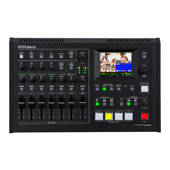
Page 6: Panel Descriptions
Panel Descriptions Top Panel/Front Panel 14 15 16 Front Panel Audio Section This section is for mixing audio and adjusting the input sensitivity of the audio channels. Name Explanation Page HDMI [1]–[4] knobs This adjusts the volume level of HDMI audio (embedded audio). p. - Page 7 This displays on the built-in monitor the screen for adjusting the amount of filter effects applied and the degree of [VIDEO FX/KEY LEVEL] button extraction for key composition. p. 24 This lights up, flashes, or goes dark according to the VR-4HD’s “HDCP” setting and the connected status of HDCP- HDCP indicator p. 17 compatible equipment.
-
Page 8: Rear Panel/Side Panel (Connecting Your Equipment)
HDMI IN 1–4 connectors, RGB/COMPONENT 4 Input connector, COMPOSITE 4 Input connector Here you connect a device used to operate the VR-4HD These are for inputting video signals from a computer or video devices such as video cameras and DVD players. - Page 9 [PHANTOM] switches The VR-4HD supports phantom power. When using a condenser microphone that requires phantom power, set the [PHANTOM] switch to “ON. ” NOTE 5 Always turn the phantom power off when connecting any device other than condenser microphones that require phantom power.
-
Page 10: Basic Operations
This displays the video currently being output. power. About the Auto Off function The power to the VR-4HD turns off automatically when all of the MEMO following states persist for 240 minutes (Auto Off function). 5 You can select either “LOW” (dark) or “HIGH” (bright) as the 5 No operation performed on the VR-4HD brightness level of the built-in monitor. -
Page 11: Working With Setup Screens (Menus)
Basic Operations Working with Setup Screens (Menus) Display for the various setup screens on the built-in monitor. In these menus change settings for video, audio and for general VR-4HD settings. Displaying/Quitting Setup Screens Selecting a Setting Item The VR-4HD has a number of different setup screens. There are... -
Page 12: List Of Supported Video Formats
List of Supported Video Formats Input Formats Output Formats Frame rate Frame rate Input connector Output connector When set at “59.94 Hz” When set at “50 Hz” When set at “59.94 Hz” When set at “50 Hz” 720/59.94p 720/50p 480/59.94i 576/50i HDMI IN 1–3 1080/59.94i... -
Page 13: Video Input/Output Settings
Set parameters for the input/output format to match the connected equipment. Setting the System Format On the VR-4HD, the input/output format is determined according to the system format. You set the input/output format to match the connected equipment. Input format (*1) -
Page 14: Setting The Input Format For Channel 4
EDID information being sent so that it matches the incoming video To specify an output format of your choice, change the setting to signal. match the setting on the device receiving the output from the VR-4HD. MEMO MEMO 5 EDID information is not sent during component signal input. -
Page 15: Assigning A Video Source To Channel 4
COMPONENT output connector) or the preview output video (PVW different connector, change this setting. OUT connector) to match the equipment receiving output from the VR-4HD. MEMO Press the [IN/OUT SETUP] button to display the setup screen. 5 You can output a color bar, useful for adjusting the image quality of a display. -
Page 16: Adjusting The Input Video On Channel 4
Video Input/Output Settings Adjusting the Input Video on Channel 4 Specifying the Video Output from the PVW OUT Connector/USB 3.0 Port For video input on channel 4, you can perform operations such as adjusting the image quality and setting the input format (EDID). For the PVW OUT connector and USB 3.0 port, you can set the video that is output to either the main output video or... -
Page 17: Inputting Copyright-Protected (Hdcp) Video
To input copyright-protected (HDCP) video from a Blu-ray Disc player or the like, follow the steps described below to change the “HDCP” setting. * The VR-4HD must be connected to an HDCP compatible display for HDCP protected video to be connected. -
Page 18: Video Operations
Video Operations Switching the Video Switching between the video inputs via channels 1 through 4. Switching by Tapping the screen Use the [TIME] knob to set the transition time. You can change the video by tapping the channel screen on the built- in monitor Press the [INPUT] button, making the button light up. -
Page 19: Switching Automatically (Auto Scan)
You can make the video on channels 1 through 4 switch automatically. MEMO You can apply fade to the VR-4HD’s main output video. 5 Any channels carrying no video input are skipped. This lets you make the main output video fade to a black (or white) picture at times when you want to suppress video output, such as during intervals in a band performance. -
Page 20: Freezing Input Video (Freeze)
Video Operations Freezing Input Video (Freeze) This temporarily pauses the incoming video. When you are changing the connections between two computers during output, freezing the output before disconnecting the first computer and then ending the freeze after connecting the second computer makes it possible to change the connections without creating noise in the output. -
Page 21: Video Effect Operations
Video Effect Operations You can apply effects to the main output video. The VR-4HD has 11 types of built-in effects: eight types of filter effects and four types of compositing effects. Using Filter Effects These apply effects such as changes in video color tone and appearance to the entire video. -
Page 22: Using Compositing Effects
Video Effect Operations Using Compositing Effects This composites video. Compositing Using Picture-in-Picture (PinP) This composites video in an inset screen over a background video. Press one of the VIDEO INPUT SELECT [1] through [4] buttons inset screen background video to select the channel you want to make the inset screen. Press the [INPUT] button, making the button light up. -
Page 23: Compositing Using Split (Split)
Video Effect Operations Compositing Using Split (SPLIT) This composites two video streams in a split screen. Tap the channel screen you want to display on side A. Specifying a Split Composition Pattern A red border is displayed around the selected channel screen. Four patterns are available for split composition. -
Page 24: Compositing Four Video Streams On A Single Screen (Quad)
This makes a portion of the video transparent and composites it onto a background video. This composites the input video on channels 1 through 4 into one With key composition on the VR-4HD, you can take video that has screen. been composited using Picture-in-Picture and the like, and further composite it with text or other video. - Page 25 Video Effect Operations Compositing Using Key Select <KEY LEVEL> and use the [VALUE] knob to adjust the amount of keying. Input the logo or video. By factory default, the settings are such that text and video input on channel 4 are used in key composition. When you want to use text or video input on another channel, use the [SYSTEM SETUP] button g <KEY>...
-
Page 26: Audio Operations
Audio Operations Adjusting the Volume Level of Input Audio You can adjust the input sensitivity, sound position, and volume balance of audio input to the VR-4HD. Adjusting Input Gain Adjust the input gain (head amp gain or digital gain) so that incoming audio signals are at appropriate levels. -
Page 27: Adjusting The Sound Position (Pan)
Output Audio The left-right position of audio is called the sound position (pan). On the VR-4HD, you can adjust the sound position of sources connected to AUDIO INPUT jacks 1 through 4 on the side panel. This adjusts the volume level of the main output audio. -
Page 28: Applying Effects To Audio
Audio Operations Applying Effects to Audio You can apply effects to audio that is input and output to adjust its sound quality. Applying Effects to Input Audio Equalizer (EQ) This applies effects to input audio and adjusts the sound quality. The effects you can use are shown in the table below. -
Page 29: Applying Effects To Main Output Audio
Audio Operations Applying Effects to Main Output Audio You can apply effects (Reverb, Equalizer, Limiter, and Multi-band Compressor) to main output audio to adjust its sound quality. Limiter (LIMITER) Press the MAIN [SETUP] button to display the setup screen. Select the setting item for the effect you want to use, then This compresses audio input that is too high, thereby preventing use the [VALUE] knob to adjust the value. -
Page 30: Hearing Only Specific Input Audio (Solo/Mute)
Audio Operations Hearing Only Specific Input Audio (Solo/Mute) You can temporarily monitor specific input audio via headphones (Solo feature). You can also temporarily silence specific input audio or output audio (mute feature). * The Solo feature affects output to headphones. It has no effect on non-headphones audio output. Solo/Mute for Input Audio Turning Off Solo/Mute Globally This turns off the setting for Solo or Mute globally. -
Page 31: Eliminating Echo In Web Conferencing Systems (Echo Cancel)
Using the Echo Cancel feature makes it possible to eliminate the echo component from audio picked up by the microphone connected to the VR-4HD and send only your own voice to the other party. -
Page 32: Controlling Fader Operation Automatically (Auto Mixing)
Controlling Fader Operation Automatically (Auto Mixing) This automatically controls fader operations that normally are performed by an operator (Auto Mixing feature). It lets you rely on the VR-4HD to perform complex fader operations, enabling use in circumstances where no dedicated operator is assigned. -
Page 33: Using The Aux Bus
Audio Operations Using the AUX Bus The VR-4HD has two built-in audio buses (a MAIN bus and an AUX bus). You can select the audio bus to output for each individual connector. MAIN bus This receives all input audio as a group and sends it to output (main output audio). -
Page 34: Interlinking Audio Output To Video Switching (Audio Follow)
Audio Operations Interlinking Audio Output to Video Switching (Audio Follow) You can associate audio with a video switch so that when the video is switched, the specified audio alone is output automatically, and other audio is automatically muted. NOTE 5 When the Audio Follow feature is on, only the switching for output and muting is performed automatically. The positions of volume-adjusting faders and knobs do not change automatically. -
Page 35: Aligning The Output Timing Of Video And Audio (Lip-Sync)
On the VR-4HD, you can delay and output the audio input via the respective channels, HDMI, and USB. Delaying audio output lets you output video and audio at the same timing. -
Page 36: Operations Using A Computer
Outputting Streaming-use Video/Audio to a Computer You can connect a computer and output video and audio mixed on the VR-4HD to it. You can also input audio played back on the computer. Using an Internet-connected computer and transfer software makes possible Internet drive transmission. -
Page 37: Other Features
Other Features Assigning Functions to USER Buttons You can assign functions to the USER [1] through [5] buttons. This lets you switch a function on and off or display a screen for accessing the function simply by pressing the USER button. By factory default, the functions appearing on the operation panel are assigned to the USER buttons. MEMO 5 You can specify which color each USER button lights up in. -
Page 38: Saving/Recalling Settings (Memory)
You can take the current settings, including video and audio settings and the state of the operation panel, and save them as a single set in memory, for later recall and use when needed. The VR-4HD is provided with eight memories. -
Page 39: Recalling A Memory
Select <MEMORY> to display the MEMORY menu. You can lock the operation of buttons and knobs to prevent inadvertent operation of the VR-4HD. Select <LOAD> to display the MEMORY LOAD screen. Press the [SYSTEM SETUP] button to display the setup screen. -
Page 40: Turning Off The Power Automatically (Auto Off )
State (Factory Reset) Auto Off is a feature that automatically turns off the power after no You can return the values of settings on the VR-4HD to their factory operation for a specific period of time. This helps prevent wasting defaults. -
Page 41: Operating The Vr-4Hd By Remote Control
You can output a tally signal or a GPO control signal from the TALLY/ GPIO connector. Using the Dedicated VR-4HD RCS Program You can use VR-4HD RCS dedicated software to remotely control the following functions on the VR-4HD from a computer connected via USB. -
Page 42: Calibrating The Tap Points On The Touch Panel
Other Features Calibrating the Tap Points on the Touch Panel The detected location on the screen when tapped might become misaligned with the location actually tapped. If this happens, calibrating the tap points can improve tapping accuracy (touch panel calibration). Press the [SYSTEM SETUP] button to display the setup screen. -
Page 43: Appendices
Appendices Troubleshooting If you suspect a malfunction, please check the following points. If this does not resolve the problem, contact a nearby Roland Service Center. Problem Items to check Action Page Video-related problems Video in a format that differs from the setting on the VR-4HD is being Is the system format set correctly? p. -
Page 44: Block Diagram
Appendices Block Diagram Video 1080p 1080i FORMAT 720p EDID I/P CONV FREEZE INPUT 1 HDMI EDID I/P CONV FREEZE INPUT 2 HDMI EDID I/P CONV FREEZE INPUT 3 HDMI EDID COLOR I/P CONV FREEZE CORRECTOR SCALER INPUT 4 Audio SIG/PEAK MUTE 3Band AUTO... - Page 45 Appendices OUTPUT FADE up to WUXGA HDMI OUT QUAD I/P CONV INPUT PinP SCALER VIDEO FX SELECT COLOR CORRECTOR SPLIT TRANSITION MIXER I/P CONV PVW OUT COLOR CORRECTOR MULTI -VIEW Built-In Monitor INPUT BUS OUTPUT BUS MAIN REVERB SOLO MAIN SOLO USB LEVEL USB DELAY...
-
Page 46: Main Specifications
Appendices Main Specifications Roland VR-4HD: HD AV Mixer Video Video Processing 4:2:2 (Y/Pb/Pr), 8-bit INPUT 1–3 HDMI Type A (19 pins) x 3 * HDCP Supported HDMI Type A (19 pins) x 1 * HDCP Supported Input Connectors RGB/COMPONENT (Mini D-sub 15-pin type) x 1... -
Page 47: Dimensions
Accessories Owner’s manual, AC adaptor, Power cord * 0 dBu=0.775 Vrms * This document explains the specifications of the product at the time that the document was issued. For the latest information, refer to the Roland website. Dimensions Unit: mm... -
Page 48: Transition Effects List
Appendices Transition Effects List Effect Explanation The two pictures are blended together as the video is switched. Video transitions are made with the luminance levels of the two video streams maintained unchanged. * This is an abbreviation of “full additive mix. ” The two video streams are compared, and transitions are made with display during transition starting with levels of high luminance. -
Page 49: Index
Index A-CENTER DEINTERLACE MODE Indicator 17, 26 11, 15, 16 ASSIGN DELAY [IN/OUT SETUP] button ATTACK Digital gain [INPUT] button Audio bus DROPPED INPUT CH LABEL DISPLAY 12, 13, 14 AUDIO FLW Input formats AUDIO FOLLOW Input gain (sensitivity) Audio format Input mode Echo cancel AUTO GAIN... - Page 50 Video Capture for VR [QUAD] button Video formats 12, 13, 14 VIDEO FX [VIDEO FX/KEY LEVEL] button 21, 25 RATIO VIDEO INPUT SELECT buttons RCS (VR-4HD RCS) View mode 27, 33 Recording (capturing) Volume 16, 22 RELEASE V POSITION Remote control...
-
Page 51: Declaration Of Conformity
DECLARATION OF CONFORMITY Compliance Information Statement Model Name : VR-4HD Type of Equipment : AV Mixer Responsible Party : Roland Corporation U.S. Address : 5100 S. Eastern Avenue Los Angeles, CA 90040-2938 Telephone : (323) 890-3700 For the USA FEDERAL COMMUNICATIONS COMMISSION RADIO FREQUENCY INTERFERENCE STATEMENT This equipment has been tested and found to comply with the limits for a Class B digital device, pursuant to Part 15 of the FCC Rules. - Page 52 For EU Countries...
Need help?
Do you have a question about the VR-4HD and is the answer not in the manual?
Questions and answers