Table of Contents
Advertisement
Quick Links
Download this manual
See also:
Technical Manual
Advertisement
Table of Contents

Related Manuals for Westerbeke 12B TWO


Summary of Contents for Westerbeke 12B TWO
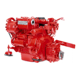
- Page 1 OPERATOR'S MANUAL WESTERBEKE 12B TWO MARINE DIESEL ENGINE Publication # 37185 Edition One January 1988 ..v- WESJ'ERBEKE WESTERBEKE CORPORATION AVON INDUSTRIAL PARK, AVON, MA 02322. TEL: (617) 588-7700...
- Page 2 SAFETY PRECAUTIONS The following symbols appear in this manual to call attention • Use Extreme Care When Handling Engine Fuel to and emphasize conditions potentially dangerous to the (A constant danger of explosion or fire exists) operator. Do not fill fuel tank(s) while the engine is running. not smoke or use an open flame near the engine or the IWARNING\ fuel tank.
- Page 3 It not only makes good sense, but is imperative that appropriate representatives of Westerbeke or the sup- plier in question be consulted to determine the accuracy and currency of the product software being con- sulted by the customer.
- Page 4 FOREWORD Thank you for selecting a Westerbeke marine product for your use. We at Westerbeke are pleased to have you as a customer. Read this manual carefully and observe all safety precautions included throughout. Operating procedures, periodic preventive maintenance procedures, installation checks, system descriptions and minor adjust- ment procedures are included herein so you can operate your equipment safely and properly, maintain the equipment at a high level of efficiency, and expect dependable performance and long service life in return.
-
Page 5: Table Of Contents
TABLE OF CONTENTS Section ................Page W 12B TWO MARINE DIESEL ENGINE GENERAL SPECIFICATIONS ..........7 W 12B TWO SYSTEM SPECIFICATIONS ......8 INSTALLATION CHECKS ..........10 PREPARATION FOR STARTING ........21 DESCRIPTION OF INSTRUMENT PANELS ....23 STARTING PROCEDURE ..........26 STOPPING PROCEDURE .......... - Page 6 "Westerbeke" plate which is mounted on the engine's exhaust manrrold. When ordering parts for your Westerbeke engine, be sure to insist upon Westerbeke factory packaged parts, because "will fit" or generic parts are frequently not made to the same specifications as original equipment.
-
Page 7: W 12B Two Marine Diesel Engine
W 12B TWO Marine Diesel Engine Fresh Water Fill Cap Fuel Injection Pump Exhaust Manifold Fresh Water gOO Exhaust Elbow Heat Exchanger Lever -----~ Zinc Anode Shut-off Lever Gear Shift Oil Pressure Lever Sender Fuel Lift Pump Lube Oil Drain Hose... - Page 8 W 12B TWO Marine Diesel Engine Amp DC Circuit Breaker Fresh Water Fill Cap Lube Oil Fill _Pretle"t Solenoid Fresh Water Air Bleed - - - " ' 0 gOO Exhaust Elbow eat Exchanger Sea Water Pump Gear Dipstick Oil Filler...
-
Page 9: General Specifications
Width: 17.75 inches (450.85 mm) Length: 24.90 inches (632.46 mm) Inclination Continuous 14 Temporary 25 (not to exceed 30 min.) Dry Weight 205 Ibs (92.9 kgs) Fuel Consumption 0.3 U.S. gph (1.14 Iph) running at 2500 rpm (approximate) Westerbeke Diesel Engines... -
Page 10: W 12B Two System Specifications
W 12B TWO SYSTEM SPECIFICATIONS FUEL SYSTEM Open flow, totally self-bleeding No.2 diesel oil (cetana rating of higher) Fuel Nippondenso (Bosch M type) I njection Pump 25° ± OS BTDC (Static) I njection Timing Nozzle Throttle type 2275.2 psi (160 kg/cm I njection Starting Pressure 12-Volt DC;... - Page 11 Standard Gear Ratio 2.47:1 Right handed - standard transmission Direction of Rotation Lubricating Oil Grade API specification of CC or CD SAE Grade SAE 20 or SAE 30 exclusively Sump Capacity 0.37 U.S. qts (0.35 liters) approximate Westerbeke Diesel Engines...
-
Page 12: Installation Checks
INSTALLATION CHECKS General Because the crafts in which Westerbeke engines are installed vary in design, installation procedures will vary according to your craft's specific design. It is not the intent of this section to advise boatyards or installers on procedures alreadywell-developed and well-understood. However, it is important that the owner/operator realize there are details of the installation which require periodic checks to ensure the best operating condi- tions for the equipment and safe operating conditions for the personnel on board. - Page 13 In case it becomes necessary to hoist the engine either front-end upwards or transmission-end upwards, the attachment of slings must be done carefully to avoid the possibility of damaging the parts on which the weight may bear. Special rigging work is best done by someone experienced and competent in handling heavy machinery. Westerbeke Diesel Engines...
- Page 14 Supports between the bed stringers, and extend- ing from the stringers to the hull, may be required for proper support and to aid in the absorption of vibrations. Note: Avoid excessive height, use (Al. solid stringer construction Westerbeke Diesel Engines...
- Page 15 The best time to pertorm the propeller shaft/transmission coupling alignment is with the fuel and water tanks about half full and all the usual equipment on board, and after the main mast has been stepped and the final rigging has been accomplished. Westerbeke Diesel Engines...
- Page 16 Take plenty of time in making this alignment and do not be satisfied with anything less than perfect results. The alignment is correct when the shaft can be easily FEELER GAGE . 3 3 3 slipped backward and forward into the counterbore, and when a feeler gauge indicates thaI the flanges come together at all points.
- Page 17 Exhaust System The exhaust system provides an outlet line to vent engine exhaust gases out of and away from the vessel. The system also discharges sea water which has passed through the engine's sea water circuit by mixing it with hot exhalJst gases. This mixing helps cool the exhaust gases and exhaust elbow and plumbing. The ex- must haust system and the sea water supply to the exhaust be configured to prevent the siphoning of sea...
- Page 18 The generator's exhaust system must be separate from any other engine's exhaust system. Dry portions of the exhaust system between the engine's exhaust manifold and the water injected exhaust elbow must be insulated to hold in the heat. Westerbeke Diesel Engines...
- Page 19 The hose cap fitting is 1/4 inch NPT (National Pipe Tap) and can be extended, or have a pump added, for easier removal of the old oil, if desired. Westerbeke Diesel Engines...
- Page 20 C), a switch located at the engine's thermostat housing area will close sound- continuous ing this alarm which will emIT a signal. Refer to the "DESCRIPTION OF INSTRUMENT PANELS" section of this manual for the location of the alarm in your engine panel, page 23. Westerbeke Diesel Engines...
- Page 21 The electrical system should be checked to ensure that all wiring harnesses are tied down properly with clamps or plastic ties, spaced at intervals close enough to prevent chafing from vibration, Check to ensure that all the engine's harness connections are tight and that they are made to the appropriate terminals, Westerbeke Diesel Engines...
- Page 22 Refer to the "SPECIFICATIONS" section of this manual for the W 12B engine's airflow requirements, page 8. Westerbeke Diesel Engines...
-
Page 23: Preparation For Starting
Follow the procedures as presented, for the conditions indicated, and your Westerbeke engine set will give you reliable performance and long service life. Fill your engine with oil up to or near the upper limit on the dipstick (the installation angle may have an effect on the dipstick reading). - Page 24 This system is common to Westerbeke Diesels. The start circuitry is designed so that the PREHEAT button must be depressed for the time specified in the "Preheat" chart shown on page 26. Then, while keeping the PREHEAT button engaged, the START button is depressed to crank the engine.
-
Page 25: Description Of Instrument Panels
DESCRIPTION OF INSTRUMENT PANELS Westerbeke offers two types of control panels as optional equipment for the W 12B engine. Read the follow· ing instructions that apply to the panel you purchased with your engine. Captains Panel General This manually-operated control panel is equipped with a key switch, an RPM gauge, a PREHEAT and START button, and an instrument test button along wtth a low oil pressure/high water temperature alarm. - Page 26 5.6Iarm: The alarm is located above the lest button and will sound if the engine's oil pressure falls below apulsating psi. In this event, the alarm will emil signal. The alarm will also sound if the water tempera- continuous ture in the fresh water cooling circuit rises to 210' F.
- Page 27 The buzzer will sound when the ignition key is turned ON and should silence when the engine has started and when the engine's oil pressure rises above 15 psi. Westerbeke Diesel Engines...
-
Page 28: Starting Procedure
Engine damage resulting from this type of sea water entry is not a warrantable issue; the owner/operator should keep this in mind. Westerbeke Diesel Engines... - Page 29 Never attempt to engage the starter while the engine is running. NOTE: Some unstable running may occur in a cold engine, but this condition should smooth out as the operating temperature of 170 - 190" F (77 - 88" C) is reached. Westerbeke Diesel Engines...
-
Page 30: Stopping Procedure
ITS full rated speed, are signs of an overload. 6. During the neX1 25 hours, the engine may be operated at varying engine speeds, with short runs at full rated speed. Avoid idling the engine for prolonged periods of time. Westerbeke Diesel Engines... - Page 31 RISE ENOUGH - Allow the glow plugs to operate sufficiently to aid in starting during the preheat period when- ever the temperature of the intake air is low and when the compression temperature does not rise enough. Refer to the preheat chart found in the "STARTING PROCEDURE" section, page 26. Westerbeke Diesel Engines...
-
Page 32: Fuel System
Although most boatbuilders supply a water trap/filter, some do not. Westerbeke offers a sedimentary/water trap/filter as an optional extra at moderate cost. The filter is supplied with fittings for etther hose or metal tubing fuel lines. - Page 33 Priming the Fuel System The Westerbeke self-bleeding fuel system is semiautomatic in operation. The self-bleeding feature of the fuel system allows for easy servicing of the fuel filters. Simply remove the and replace the filter elements (take care in catching any fuel that may drain out of the fuel filtering assemblies) as described in the "Replacing the Fuel Filter Elements"...
- Page 34 To obtain long and satisfactory service from the injection pump, always use fuel which is free from impurities and maintain a good filtration and water separation system between the fuel tank and generator engine. Ser- vice this system regularly: the injection pump it saves may be your own. Westerbeke Diesel Engines...
-
Page 35: Electrical System
Engine 12-Volt DC Control Circuit The Westerbeke W 128 TWO propulsion engine has a 12-Volt DC electrical control circuit, as shown on the wiring diagrams which follow on pages 34 to 37. Refer to these diagrams when troubleshooting or servic- ing electrical components on the engine. -
Page 36: The Captains Panel Wiring
SAFETY 5W"TC" 'u'(~ ~OC'" 0" ", .. ( .. l j , ' "i" ,I ,[ !)!\ '~I; ~! ~ "I'E " "il ' , i'i "'\\ ,,'}: ',' \fi I '-' CAPTAIN PANEL '''E'' ',... -----------------------~ Westerbeke Diesel Engines... -
Page 37: Dc Wiring Diagram #36467 Showing The Captains Panel Wiring
DISCONNECT THE SAnERV' Ir-I All ArlO .. HEN TI1E eOt-T t- S' .. ITe,. A~PS WIT" A CONTiNUOUS -"AT!NG OF 17:' 12\10C WILL SERvE iHIS FUNCTtOr. MAKE 0R 5\.o1 TCH SHOULD NOT BE USEI) TO BREAI( THE CIReUI'";'. Westerbeke Diesel Engines... -
Page 38: Dc Wiring Diagram #36844 Showing The Admirals Panel Wiring
-, ,-, ,i ----T~ i"e~ ' - ' " \" i i i ""'Go,,, """'''J ~\<GH'. ~G"~\~V" ---;;:';~--'~ iiI.. I~' -~, ADMIRAL ~"--' PANEL ~\[IC~ /T~HOMETER , ' " ----~-,~,', START PREHEAT KEy SWITCH SWITCH SWITCH VOLTMETER no!;" Westerbeke Diesel Engines... -
Page 39: Dc Wiring Diagram #36844 Showing
A CONTINUOUS RATING OF 175 AMPS AT 12 VOLTS DC WILL. SERVE THIS FUNCTION. THIS SWITCH SHOULD NOT BE USED TO MAKE OR BREAK THE CIRCUIT. 3. THE GRAY WIRE AT PLUG #2 IS UNUSED AND SHOULD BE INSULATED. Westerbeke Diesel Engines... - Page 40 Note: Before removing the alternator for repair, ensure that 12-Volts excitation is present at the R terminal should the above test show only battery voltage at the B output terminal. Westerbeke Diesel Engines...
-
Page 41: Cooling System
COOLING SYSTEM Description Westerbeke marine diesel engines are designed and equipped for fresh water cooling. Heat produced in the engine by combustion and friction is transferred to fresh water which circulates throughout the engine. This circulating fresh water cools the engine block and its internal moving parts. The heat is transferred external- ly from the fresh water to sea water by means of a heat exchanger, similar in function to an automotive radiator. - Page 42 B. Filling the Fresh Water System A coolant recovery tank kit is supplied with each Westerbeke diesel engine. The purpose of this recovery tank is to allow for engine coolant expansion and contraction, during engine operation, Without the loss of coolant and without introducing air into the cooling system.
- Page 43 Since 1980, each type of thermostat has a hole punched through it. The hole is a bypass to prevent the ex- haust manifold from overheating during the engine's warm-up. Replacement thermostats must have this design characteristic. Westerbeke Diesel Engines...
- Page 44 Excessive slack or the presence of oil on the belt can cause belt slipping, resulting in high operating tempera- ture, as well as insufficient alternator output. Westerbeke Diesel Engines...
- Page 45 3/8 inch and no more than 1/2 inch (10 mm, 12 mm) as the belt is depressed with the thumb at the midpoint between the two pulleys on the longest span of the belt (See the figure below.) A spare drive belt should be carried on board. Alternator and Water Pump Belt Tension Westerbeke Diesel Engines...
- Page 46 Illustrated below is a typical Westerbeke engine's cooling system, Both fresh water and sea water flow through their independent cooling circuits, Refer to your engine's Parts List for part numbers and part descriptions if you need to order cooling system parts for your engine,...
- Page 47 FLOW BACI( FLOW OUT OF HEATER COILS BELOW PRESSURE CRP ENGINE £t(GIN£ The illustrations shown above are Flow Control designs which have been adapted to operate with the single pass manifolds installed on the 12B TWO diesel engine. Westerbeke Diesel Engines...
- Page 48 The hose connection from the heater to the remote expansion tank should be rou1ed and supported so as to rise continuously from the heater to the tank, enabling any air in the system to rise. Refer to the illustrations on the previous page. Westerbeke Diesel Engines...
-
Page 49: Lubrication System
NOTE: A newly started, cold engine can have an oil pressure reading upwards of 60 psi. A warmed engine can have an oil pressure reading as low as 35 psI. These readings will vary depending upon the speed at which the engine is running. Westerbeke Diesel Engines... - Page 50 Immediately after an oil filter cnange and oil fill, run the engine to ensure that the oil pressure Is normal and that there are no oil leaks around the new oil filter. Westerbeke Diesel Engines...
- Page 51 Ensure there is no leakage around the new oil filter or from the oil drain system, and then stop the engine. Then check the quantity of oil with the lube oil dipstick. Fill to, but not over, the high mark on the dipstick, should the engine require additional oil. Westerbeke Diesel Engines...
-
Page 52: Hbw 50 Transmission
10 to 15 minutes so the transmission fluid may warm and flow better from the transmission. This transmission fluid may also be removed by inserting a small tube through the dipstick opening (where the transmission fluid is added) and attaching a pump onto the tube so the old fluid may be sucked out. Westerbeke Diesel Engines... - Page 53 The operating oil temperature must not exceed 266' F (130' C). If this temperature is to be exceeded during normal operation, an optional transmission oil cooler should be installed. Consult you local Westerbeke Dealer for details on this cooler. NOTE: To check the transmission fluid level, remove the dipstick and wipe off all transmission...
- Page 54 Make sure the remote control lever is lubricated at lease once each operating season. Shift the transmission while the engine is running at 1200 rpm or below, The clutch pack within the transmission makes an audiable "clunk" when engaging into gear. Westerbeke Diesel Engines...
- Page 55 120 x 8 P -tlade or 12 0 x 6 P - 3 blade (using optional HBW 50 Propeller should allow the engine to reach transmission with 2.5:1 reduction) its full rated RPM (3600 000 - 100) at full open throttle while underway. Westerbeke Diesel Engines...
-
Page 56: Bw 3 Transmission
To ensure that most of the old oil is drained from the transmission, run the engine in NEUTRAL for ap- proximately 10 to 15 minutes so the transmission oil may warm and flow better from the transmission. This Westerbeke Diesel Engines... - Page 57 The operating oil temperature must not exceed 266' F (130' C), If this temperature is to be exceeded during normal operation, an optional transmission fluid cooler should be installed, Consult you local Westerbeke Dealer for details on this cooler, NOTE: To check the transmission fluid level, remove the dipstick and wipe off all transmission...
- Page 58 NOTE: Never loosen the four gear box lever cover screws, except in the course of qualified servicing; this upsets critical adjustments. Disassembly of the transmission in the field is not recommended. If an overhaul or repair is needed, the work should be done by Westerbeke or an authorized Westerbeke service center.
-
Page 59: Engine Troubleshooting
ENGINE TROUBLESHOOTING Introduction The tables which follow indicate troubleshooting procedures based upon certain problem indicators, the probable causes of the problems, and the recommendations to overcome these problems. Note that the engine's control system (electrical system) is protected by a 20-Ampere manual reset circuit breaker located on the rear lifting bracket. - Page 60 4. Check pump operation. operating. 5. Fuel filters are clogged. 5. Clean/replace filters. Failure to stop. 1. Mechanical Run 1. Stop engine by man- linkage disconnected. ually moving the RUN linkage to STOP. That failing, shut off fuel and air. Westerbeke Diesel Engines...
- Page 61 B terminal on the alternator. 2. Faulty alternator. 2. Voltage leak through the alternator when not operating. 3. Bad battery 3. Connections are corroded orland connections. or loose at the battery at the engine. Westerbeke Diesel Engines...
-
Page 62: Maintenance & Adjustments
Servicing After Initial Hours 01 Operation 1, Change the engine's lubrication oil and oil filter, 2, Replace the fuel filter element in the electric fuel lift pump and in the optional water/sediment separator, if a separator has been installed, Westerbeke Diesel Engines... - Page 63 *4. Check the condition 01 the starler motor drive pinion; lubricate the pinion. 5. Check the resiste!11ce of the glow plugs. (.4 to .6 ohms) NOTE: Items highlighted by an asterisk should be performed by a competent mechanic. Westerbeke Diesel Engines...
- Page 64 NOTE: Operating in silty and/or tropical waters may require that a heat exchanger cleaning be performed more often than every 1000 hours. *2. Check the injection pump's timing. Westerbeke Diesel Engines...
- Page 65 (refer to the photograph shown below). Nowad- just the NO.1 piston's intake and exhaust valves. 25" BlOC INJECTION PUMP TIMING MARK MARK GEAR-~. ~ ++-+++-+~-T- CASE TOP DEAD CENTER ALIGNMENT MARK Westerbeke Diesel Engines...
- Page 66 Now adjust the No.2 piston's intake and exhaust valves. NOTE: Adjust all valves to 0.0098 inches (0.25 mm) with the engine cold. ADJUST VALVES TO 8.8898 INCHES [8.25 Adjusting a valve's clearance with a feeler gauge. Westerbeke Diesel Engines...
- Page 67 PlDNHR CONTROL PUlIOM TAPPET PlUNGER SPIII1I6 Cutaway View of the W 12B TWO's Fuel Injection Pump Move the throttle lever to mits full open position and INJECTION operate the electric lift pump. Rotate the crankshaft TIMING clockwise (as viewed from the front). catching the fuel MIIRK ON from the No.1 fuel line, until the instant the fuel com-...
- Page 68 To advance the timing, decrease the shim thick- ness, as required. To retard the timing, increase the shim thickness, as required. Refer to your engine's parts List for shim part numbers. DELIVERY VALVE HOLDER INJECTION PUMP ADJUSTING SHIM Fuel Injection Pump wtth Adjusting Shim Westerbeke Diesel Engines...
-
Page 69: Lay-Up & Recommissioning
Fill the sump with the correct amount of oil for your engine. (Refer to the"SYSTEM SPECIFICATIONS" section of this manual, page 8.) Use an oil with an API specification of CC or CD. Run the engine and check for proper oil pressure and ensure that there are no leaks. Westerbeke Diesel Engines... - Page 70 Lubrication and cleaning of the starter drive pinion is advisable, access to the starter permITs ITS easy removal. Ensure that the battery connections are shut off before attempting to remove the starter. Take care in properly replaCing any electrical connections removed from the starter. Westerbeke Diesel Engines...
- Page 71 Spares Lay-up time provides a good opportunity to inspect your Westerbeke engine to see if external items such as drive belts or coolant hoses need replacement. Check your basic spares kit and order items not on hand, or replace those items used during the lay-up, such as filters and zinc anodes.
- Page 72 When the engine is put Into operation, the system will self-flush in a short period of time with no ad- verse affects. 5. Start the engine in accordance with procedures in the "PREPARATIONS FOR STARTING" section of this manual, page 21. Westerbeke Diesel Engines...
-
Page 73: Table Of Standard Hardware Tightening Torques
3.7-4.6 3/8 UNF 30 - 35 4.1 - 4.8 7/16 UNC 44 - 49 6.1 - 6.8 7/16 UNF 50 - 55 6.9 - 7.6 1/2 UNC 68 - 73 9.4-10.1 1/2 UNF 73 - 80 10.1-11.1 Westerbeke Diesel EnginE... -
Page 74: Torque Specifications
Nozzle holder and retaining nut 43.4 - 57.9 6.0 - B.O 1.5 - 2.0 Glow plug 10.8 - 14.5 1.0 - 1.2 Starter B terminal nut (on copper stud) 7.2 - 8.7 NOTE: indicates Metric, 8 mm thread diameter Westerbeke Diesel Engines... -
Page 75: Spare Parts
From the list provided directly above and from these inquiries, you can determine what spare parts may be needed. In addition, you are planning a long ocean voyage, consult your local Westerbeke dealer for a listing of the Westerbeke dealers located on your route. Westerbeke Diesel Engines... -
Page 76: Index
Control Circuit, Engine 12-Volt DC,.,.,.,.,.,..,.. ,.,.,.,.,.,. .. ,.,.. ,.,.,.,.,.,.,.,.. ,.,.,. .. ,.,.,.,.,.,..,.,..,..,.,.,..,..,..,.,.,..,.. ,.33 Coupling, Propeller (Installation Checks) ,.,.,.,..,..,.,.,..,..,..,.,.,..,..,.,..,.,.,.,..,..,..,.,.,.,.,.,..,. .. ,. .. ,.,.,. .. ,..,.,..,.,..13 Coupling, Propeller (Lay-up and Recommissioning) ,.,.,..,..,..".,..,.,.,.,.,..,..,..,.,.,.,.,..,.,..,..,.,.,.,..,..,..,..,.,.,. .. 67 Cylinder Head Bolts, Torquing ........................63 Westerbeke Diesel Engines... - Page 77 ENGINE TROUBLESHOOTING ........................57 Equipment. Inspection of ..........................2 Exhaust Back-Pressure (Installation Checks) .................... 16 Exhaust. Intake Manifold and Through-Hull (Lay-up and Recommissioning) .......... 68 Exhaust System (Installation Checks) ......................15 Exhaust System Failures (Installation Checks) ..................17 Westerbeke Diesel Engines...
- Page 78 Lifting, Rigging and (Installation Checks) ....................11 Location (Installation Checks) ........................10 Lubrication (BW 3 Transmission) ........................ 54 Lubrication, Cylinder (Lay-up and Recommissioning) ................69 Lubrication (HBW 50 Transmission) ......................50 Lubrication System (Lay-up and Recommissioning) ................. 67 Westerbeke Diesel Engines...
- Page 79 Pump, Fuel Injection ....................... 32 ....65 Pump, Injection, Timing Adjustment ................... 42 Pump, Sea Water ....................... . Westerbeke Diesel Engines...
- Page 80 Fuel (Installation Checks) ......................19 Fuel (Lay-up and Recommissioning) ....................68 FUEL......................~ Intake, Sea Water (Installation Checks) .................... 19 Lubrication (Lay-up and Recommissioning) ..................67 LUBRICATION ........................... 47 Priming the Fuel ..........................31 SPECiFiCATIONS ..........................8 Westerbeke Diesel Engines...
- Page 81 TABLE OF STANDARD HARDWARE TIGHTENING TORQUES ............. 71 Tension, Alternator and Water Pump Drive Belt ................42 Test, Charging Voltage ........................38 THE BW 3 TRANSMiSSiON......................THE HBW 50 TRANSMISSION ......................
- Page 82 YOUR NOTES...
Need help?
Do you have a question about the 12B TWO and is the answer not in the manual?
Questions and answers