Table of Contents
Advertisement
Advertisement
Table of Contents
Troubleshooting

Related Manuals for Westerbeke 63B


Summary of Contents for Westerbeke 63B
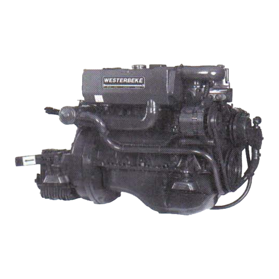
- Page 1 638 and 63C FOUR 71 8 and 71 C FOUR 828 FOUR 1088 and 108C SIX MARINE DIESEL ENGINES PUBLICATION NO. 038922 EDITION FIVE OCTOBER 2006 WESTERBEKE CORPORATION' 150 JOHN HANCOCK ROAD MYLES STANDISH INDUSTRIAL PARK' TAUNTON MA 02780 WEBSITE: WWW.WESTERBEKECOM...
- Page 2 Shut down the unit and do not restart until it has been Inspected and repaired. ~---------' A WARNING DECAL is provided by WESTERBEKE and should be nxed to bulkhead near your engine or generator. \ WESTERBEKE also recommends installing .. \ CARBON MONOXIDE DETECTORS in the WA R N I N GI living/sleeping quarters of your vessel.
- Page 3 SAFETY INSTRUCTIONS INTRODUCTION • Do not operate with the air cleaner/silencer removed. Backfire can cause severe injury or death. Read this safety manual carefully. Most accidents are • Do not smoke or permit flames or sparks to occur near caused by failure to follow fundamental rules and precau- the fuel system.
- Page 4 SAFETY INSTRUCTIONS ACCIDENTAL STARTING TOXIC EXHAUST GASES WARNING: Accidental starting can cause injury WARNING: Carbon monoxide (CO) Is deadly gas! death! • Ensure that the exhaust system is adequate to expel gases • Disconnect the battery cables before servicing the engine/ discharged from the engine.
- Page 5 SAFETY INSTRUCTIONS ABye, NFPA AND USCG PUBLICATIONS FOR • Do not wear loose clothing or jewelry when servicing equipment; tie back long hair and avoid wearing loose INSTALLING DIESEL ENGINES jackets, shirts, sleeves, rings, necklaces or bracelets that Read the following ABYC, NFPA and USCG publications could be caught in moving parts.
- Page 6 INSTALLATION When installing WESTERBEKE engines and generators it is important that strict attention paid to the following infom1ation: CODES AND REGULATIONS Strict federal regulations, ABYC guidelines, and safety codes must be complied with when installing engines and generators in a marine environment.
-
Page 7: Table Of Contents
TABLE OF CONTENTS Remote Oil Filter (Optional) ......Parts Identification ..........Water Heat Connections ........Introduction ............Warranty Procedures .........3 Wiring Diagram ..........26 Serial Number Location ........4 Wiring Schematic ..........Admiral Control Panel ......... 5 Glow Plugs ............Captain Control Panel ......... -
Page 8: Parts Identification
PARTS IDENTIFICATION (TYPICAL) FILL COOlANT WATER INJECTED PRESSURE CAP EXHAUST ELBOW ASSEMBLY FILTER DC CHARGING AIR INTAKE ALTERNATOR SILENCER WMERHtAltK·-------~ CONNECTION REAR FLEXIBLE MOUNT DRIVE BELT RAWWATERP~ FILTER COOLER CRANKSHAFT PULLEY PRESSURE LEFT SIDE SENDOR OIL DRAIN HOSE Fill THERMOSTAT _",~"o;;l"'DLY LIFT FUEL... -
Page 9: Introduction
WESTERBEKE customers should keep mind the time WESTERBEKE dealer. If you are planning to install this span between printings ofWESTERBEKE product software equipment, contact your WESTERBEKE dealer for and the unavoidable existence of earlier WESTERBEKE WESTERBEKE'S installation manual. -
Page 10: Serial Number Location
WES1ERBEKE engine. Your local WES1ERBEKE dealer will assist you in preparing an inventory of spare parts. See the SPARE PARTS page in this manual. For engine accessories, see WESTERBEKE'S ACCESSORIES brochure. RAW WATER COOLING SYSTEM UNDERSTANDING THE DIESEL ENGINE Siphon-Break The diesel engine closely resembles the gasoline engine, since the mechanism is essentially the same. -
Page 11: Admiral Control Panel
ADMIRAL CONTROL PANEL DESCRIPTION When the engine is shut down with the key switch turned off, the water temperature gauge will continue to register the last This manually-operated control panel is equipped with a temperature reading indicated by the gauge before electrical KEY switch and RPM gauge with an ELAPSED TIME power was turned off. -
Page 12: Captain Control Panel
CAPTAIN CONTROL PANEL DESCRIPTION The panel also includes an alarm buzzer for low OIL PRESSURE high COOLANT 1EMPERATURE. The This manually-operated control panel is equipped with a RPM gauge is illuminated when the KEY switch is turned on KEY switch, an RPM gauge, PREHEAT and START but- and remains illuminated while the engine is in operation. - Page 13 DIESEL FUEL, ENGINE OIL AND ENGINE COOLANT DIESEL FUEL ENGINE COOLANT WESTERBEKE recommends a mixture of 50% antifreeze Use fuel1hat meets 1he requirements or specification of Class 2-D (ASTM), and has a cetane rating of #45 or better. and 50% distilled water. Distilled water is free from the...
-
Page 14: Preparations For Initial Start-Up
PREPARATIONS FOR INITIAL START-UP PRESTARTINSPECTION Before starting your engine for the first time or after a prolonged layoff, check the following items: COOlANT Check the engine oil level. Add oil to maintain the level 'RECOVERY at the high mark on the dipstick. TANK Turn on the fuel supply, then check the fuel supply and examine the fuel filter/water separator bowl for... - Page 15 STARTING - STOPPING PROCEDURE CHECKLIST FAILURE TO START If the engine fails to start when the start button is pressed for Follow this check list each day before starting your engine. 5 seconds, wait for at least 30 seconds and repeat the starting Visually inspect the engine for fuel, oil, or water leaks.
-
Page 16: Engine Break-In Procedure
ENGINE BREAK-IN PROCEDURE 3. While using the vessel, run the engine at various engine DESCRIPTION speeds for the first hours. Avoid prolonged periods of Although your engine has experienced a minimum of one idling. hour of test operations at the factory to make sure accurate 4. -
Page 17: Warning Lights, Alarms And Circuit Breaker
WARNING LIGHTS, ALARMS & CIRCUIT BREAKER ALTERNATOR WARNINGS LOW OIL PRESSURE ALARM SWITCH The Captain Control Panel indicates alternator low discharge A low oil pressure alarm switch is located off the engine's with a warning light oil gallery. This switch's sensor monitors the engine's oil pressure. -
Page 18: Maintenance Schedule
MAINTENANCE SCHEDULE WARNING: Never attempt to perform any service while the engine is running. Wear the proper safety equipment such goggles and gloves, and use the correct tools for each job. Disconnect the battery terminals when servicing any of the engine's DC electrical equipment. NOTE: Many of the following maintenance jobs are simple but others are more difficult... - Page 19 At first 50 hours. then every 500 hours Hold-down bolts (see ENGINE ADJUSTMENTS). *Adjust the Valve Clearances Adjust Valve Clearances (see ENGINE ADJUSTMENTS). "Heat Exchanger Remove. have profeSSionally cleaned and pressure tested. *WESTERBEKE recommends this service be performed by an authorized mechanic. Engines & Generators...
-
Page 20: Fuel System
FUEL SYSTEM DIESEL FUEL Use No.2 diesel fuel with a cetane rating of 45 or higher. Do not use kerosene or home heating fueL FUEL FILTER/WATER SEPARATOR primary fuel filter of the water separating type must be installed between the fuel tank and the engine to remove water and other contaminants from the fuel before they can be carried to the fuel system on the engine. -
Page 21: Cooling System
COOLING SYSTEM FRESH WATER COOLING CIRCUIT CHANGING COOLANT The engine's coolant must be changed according to the NOTE: Refer to the ENGINE COOLANT page for the MAINTENANCE SCHEDULE. If the coolant is allowed to recommended antifreeze water mixture to be used as become contaminated, can lead to ovetbeating problems. -
Page 22: Thermostat
COOLING SYSTEM THERMOSTAT RAW WATER INTAKE STRAINER A thennostat, located near the manifold at the front of the NOTE: Always install the strainer at or below waterline so engine, controls the coolant temperature as the coolant the strainer always be self-priming. will continuously flows through the closed cooling circuit. -
Page 23: Raw Water Pump
COOLING SYSTEM Changing the Raw Water Pump Impeller RAW WATER PUMP Close the raw water intake valve. Remove the pump cover The raw water pump a self-priming, rotary pump with a and, with the aid of two small screwdrivers, carefully pry the non-ferrous housing and a Neoprene impeller. -
Page 24: Heat Exchanger
COOLING SYSTEM Zinc Anode If the zinc anodes need replacement, hold the hex boss into which the zinc anode is threaded with a wrench while loos- A zinc anode, or pencil, is located in the raw water cooling ening the anode with another wrench. This prevents the hex .circuit within the heat exchanger. -
Page 25: Engine Lubricating Oil
ENGINE LUBRICATING OIL DESCRIPTION ENGINE Oil CHANGE 1. Draining the Oil Sump. Discharge the used oil througn The lubricating system is a pressure feeding system using the sump drain hose (attached to the front of the engine) an oil pump. The engine oil is drawn from the oil sump by while the engine is wann. - Page 26 100 hours of operation discard clothing rags containing used oil. Discard thereafter. For reconnnended oil use SAE 15W-40 (oil viscosity). WESTERBEKE reconnnends the use of used oil properly. synthetic oil. NOTE: Generic jilters are not recommended, as the...
-
Page 27: Remote Oil Filter (Optional)
REMOTE OIL FILTER (OPTIONAL) JNSTALLATION NOTE: Westerbeke is responsible for engine failure due to incorrect installation of the Remote Oil Filter. !fhls popular accessory is used to relocate the engine's oil fil- ter from the engine to a more convenient location such as an ~ngine room bulkhead. - Page 28 WATER HEATER CONNECTION KIT (71B & C, 82B FOUR, & 107 B & C) The models refered to in this manual are equipped with connections for the plumbing of engine freshwater coolant to a domestic hot water heater. One connection (to) is located on the lower side ofthe exhaust manifold. The other connection (return) is located on the center outer surface of the heat exchanger.
- Page 29 The pressure cap on the engine's manifold should be installed once the engine's cooling system is filled with coolant. Finish filling the cooling system from the remote tank once the system is filled and is free of air and exhibits good coolant circulation.
-
Page 30: Water Heat Connections
WATER HEATER CONNECTIONS (71 C & 828 FOUR) FOR PRODUCTION MODELS FROM MARCH 2004 ON NOTE: WESTERBEKE provides easy access for connecting to an An air bleed petcock is located on the engine:V heat on-board hot water system. These connections allow for the exchanger on the thermostat housing. - Page 31 With the engine running, inspect for leaks and check for normal temperature. NOTE: For additional information on the proper installation of your water system, refer to your engine/generator operators manual or contact your WESTERBEKE dealer. Engines Generators &...
-
Page 32: Wiring Diagram
WIRING DIAGRAM r~11 'A~'~ - - UI MOon.S) $EE HOT[ 2, LIFT PUMP IIOTE: An on-off switch should be installed In this circuit to disconnect the starter from the battery in emergency and when leaving the .boat Twelve '2m'" volt engine staffers typically draw 200 to 300 ADMIRAL amps when cranking, A... -
Page 33: Wiring Schematic
WIRING SCHEMATIC SS~Rr 12 VDe S'tdHR ~-------7;~~rl 171------~'H~ ------------1-----. IS PROTECTED SY A RESET CIRCuIT SR"'rR Pft(ItUT THE SRU.KEIt 10 nl9' A XCU$IYE CURRENT WILL ~_..,. ---:r~- TItE eUILOER/OWNtR SURE THAT THE tNST IIISU"ED TO PREVEII T eErrEE" ELECTRIC " --;I'll I Q/Ij,.orr SWITCH SHOULD BE INSTALtED BUWtEf,I TH£... -
Page 34: Glow Plugs
GLOW PLUGS Re--install the plugs in the engine and test them again. The DESCRIPTION plugs should get very hot (at the terminal end) within 7 to 15 The glow plugs are wired through the preheat solenoid. seconds. If the plugs don't heat up quickly, check for a short When PREHEAT is pressed at the control panel this solenoid circuit When reinstalling the glow plugs, use anti-seize should "click"... -
Page 35: Starter Motor
STARTER MOTOR DESCRIPTION The starter is a new type, small, light-weight and is called a high-speed internal-reduction starter. The pinion shaft is separate from the motor shaft; the pinion slides only on the pinion shaft. A reduction gear is installed between the motor shaft and a pinion shaft. - Page 36 SERVICE If the starter fails to spin, the motor is probably faulty. WESTERBEKE uses a standard starter motor which can be If no arching occurred, there is no juice reaching the serviced or rebuilt at any starter motor automotive service solenoid.
-
Page 37: Dual Output Alternators
INSTALLATION If an optional dual alternator has already been factory installed, simply follow the WESTERBEKE wiring diagram and the engine installation instructions. the new dual alternator is being added to existing "in- the-boat"... - Page 38 DUAL OUTPUT ALTERNATORS TROUBLESHOOTING Alternator Testing NOTE: The regulator is functioning properly and the batteries Before troubleshooting, make certain that the drive belts are tight and the batteries are in good condition. are in good condition. 1. Test the voltage at the alternator plug with the engine Regulator Testing off-key on.
- Page 39 Dual output and high output alternators are available as positive cable. optional equipment on most WESTERBEKE engines. These 6. Mount the regulator to a flat surface in a cool dry location. alternators can be installed during factory assembly or as add-on equipment at anytime.
-
Page 40: Alternator Testingjtroubleshooting
VOLTAGE REGULATOR The following infonnation applies to the standard alternators The integral voltage regulator is an electronic switching that are supplied with WESTERBEKE'S Marine Engines device which senses the system voltage level and switches and Marine Generators. the voltage applied to the field in order to maintain a proper system voltage. - Page 41 ALTERNATORS TESTING/TROUBLESHOOTING PRELIMINARY INSPECTION Thrn off the engine. Inspect all wiring and connections. Ensure that the battery terminals and the engine ground Before starting the actual alternator and voltage regulator, connections are tight and clean. testing the following checks are recommended. 4.
- Page 42 2. Turn the ignition switch to the on position and note shop can do the job. the multimeter reading. The reading should be 1.3 to 2.5 volts (see illustration). NOTE: WESTERBEKE'S Service Manual has detailed instructions for the disassembly repair of their standard altemators.
-
Page 43: Engine Troubleshooting
ENGINE TROUBLESHOOTING The following troubleshooting table describes certain problems NOTE: The engine electrical system is protected by a 20 relating engine service, the probable causes of these prob- ampere manual reset circuit breaker located on a bracket at lems, and the recommendations to overcome these problems. the back of the engine. - Page 44 ENGINE TROUBLESHOOTING Problem Probable Cause Verification/Remedy Engine slows and stops. Fuel lift pump failure. Fuel lift pump should make a distinct ticking sound. Replace pump with spare. Switches and/or wiring loose Inspect wiring for short circuits and loose connections. or disconnected. Inspect switches for proper operation.
-
Page 45: Service Schedule
SERVICE SCHEDULE Servicing After Every 100 Hours of Operation Change the engine's lubrication oil and oil filter. 2. Adjust the alternator and water pump drive belt tension, if required. Lubricate panel keyswitch (use "Lockeze" only). 4. Inspect the syphon-break assembly for proper operation. installed) (When Servicing After Every 250 Hours of Operation... - Page 46 Adjust the alternator and water pump drive tension, if required. belt 6. Lubricate the throttle and the transmission's control cable check for proper operation and movement. 7. Change the transmission's lubricant. 8. Adjust the engine's idle speed (750 - 1000 rpm). WESTERBEKE Engines Generators &...
-
Page 47: 7Ib Four & 82B Four
SERVICE SCHEDULE CYLINDER HEAD BOLT TORQUING Servicing After Every 1000 Hours of Operation 1. Remove, clean, and pressure test the primary heat exchanger. (A local automotive radiator shop should be able to clean and test the heat exchanger.) in silty and/or tropical waters may require that a heat exchanger cleaning be NOTE: Operating performed more often than every 1000 hours. -
Page 48: Four & 82B Four
SERVICE SCHEDULE CYLINDER HEAD BOLT TORQUING Tighten the cylinder head bolts to the specified torque before making valve adjustments. When No.1 cylinder dead enler When No.1 cylinder is at top dead center (l~EX TINC!.'EX 1 '~31IN (fiN (rEX When NoA cylinder top dead center 63(BXC)FOUR, 71(B)(C)FOUR 108(BXC) -
Page 49: Engine Adjustments
ENGINE ADJUSTMENTS NOTE: WESTERBEKE recommends that the following engine adjust- ments be performed a competent engine mechanic. information below provided to assist mechanic. ENGINE IDLING SPEED INJECTION PUMP SERVICE The engine idling speed is pre-set at the factory but once the... - Page 50 TACHOMETER TACHOMETER/HOUR METER NOTE: Current model tachometers use a coarse adjustment dial to set the tachometer to the crankshaft pulley rpms. The The tachometerlhour meter used in propulsion engine instru- calibrating screw is then used for fine tuning. ment panels contains two separate electrical circuits with a common ground.
-
Page 51: Oil Pressure
OIL PRESSURE NOTE: WESTERBEKE recommends that the following engine adjustments he peifomled by a competent engine mechanic. The infomtation below is provided to assist the mechanic. DESCRIPTION OIL PRESSURE The lubricating system is a pressure feeding system using an The engine's oil pressure, during operation, is indicated oil pump. -
Page 52: Engine Specifications
SPECIFICATIONS 638 AND 63C FOUR MARINE DIESEL ENGINES ENGINE SPECIFICATIONS COOLING SYSTEM Engine Type Diesel, four-cycle, fresh water-cooled, vertical General Fresh water-cooled block, themnostatically- in-line (63 hp at 3600 rpm maximum) controlled with raw water heat exchanger sys- Governor Integral ofthe injection pump, mechanical flywheel type Operating Temperature 170 -190°... - Page 53 SPECIFICATIONS 71 BAND 71 C FOUR MARINE DIESEL ENGINES ENGINE SPECIFICATIONS COOLING SYSTEM Engine Type Fresh water-cooled block, thermostatically- Diesel, four-cycle, four cylinder, fresh General controlled with raw water heat exchanger sys- water-cooled, vertical in-line (71 hp at 3600 rpm maximum) Govemor Integral of the injection pump, mechanical Operating Temperature...
- Page 54 SPECIFICATIONS 828 FOUR MARINE DIESEL ENGINE FUEL SYSTEM ENGINE SPECIFICATIONS General Open flow, self priming - 1 bleed point. Engine Type Diesel, four-cylinder, four-cycle, fresh water-cooled, vertical in-line overhead valve No.2 diesel oil (cetane rating of 45 or higher) Fuel mechanism.
- Page 55 SPECIFICATIONS 1088 AND 108C FOUR MARINE DIESEL ENGINES ENGINE SPECIFICATIONS COOLING SYSTEM Fresh water-cooled block, thermostatically- Engine Type Diesel, four-cycle, four cylinder, fresh General controlled with raw water heat exchanger sys- water-cooled, vertical in-line (108 hp at 3600 rpm maximum) Operating Temperature 170 -190°...
-
Page 56: Zf Marine Transmission
CONNECTION OF GEAR BOX WITH PROPELLER threaded holes located above the shift cover on top of the gear housing. Refer to the WESTERBEKE parts list. HEW recommend a flexible connection between the transmission gearbox and the propeller shaft if the engine is... - Page 57 ZF MARINE TRANSMISSIONS INITIAL OPERATION OPERATING TEMPERATURE All HBW marine transmissions are test-run on test stand The maximum pennissible ATF temperature should not exceed 230" (110°). temperature reached with the engine at the factory prior to delivery. safety This can only be short reasons the fluid is drained before shipment.
- Page 58 DAILY OPERATION the tubes and back into the transmission. Check the transmission fluid. Visually check the gear shift linkage and transmission. WESTERBEKE RECOMMENDS • RAW WATER HAVING A SPARE COOLER Start the engine in neutral, allowing a few minutes at idle...
- Page 59 Check the O-rings for damage and replace if prevent internal corrosion (extended storage only, twelve necessary. Replacement filters can be obtained from your months or more). local WESTERBEKE dealer or ZF dealer.!> Loosen attaching hardwarf? from transmission output Removing the Fluid flange and propeller shaft coupling flange before removing the boat from the water.
- Page 60 PROPELLEa---- the gear lwusing. Refer to the WESTERBEKE parts list. ROTATION For additional infonnation contact: A=RH N-NEUTRAL...
- Page 61 WESTERBEKE recommends having a spare cooler aboard. Inspect the gear shift cable, linkage, and attachments. Look for corrosion of the end fittings, cracks or cuts in the conduit, and bending of the actuator rods.
- Page 62 NOTE: lfyou suspect a major problem in your transmission, is stiff to operate, break the cable loose at the transmission immediately contact your WESTERBEKE dealer or an again. If it is still stiff, check the cable for kinks or autlwrized marine transmission facility.
- Page 63 BORG WARNER VELVET DRIVE TRANSMISSION OPTIONAL TRANSMISSION SHIFT LEVER POSITION shift The gear control mechanism and linkage must position the actuating lever on the transmission exactly in Forward Neutral and Reverse (R) shifting positions. A dete])t (F), (N), ball located behind the transmission lever must work freely to center the lever in each position.
- Page 64 BORG WARNER VELVET DRIVE TRANSMISSION Clean off the transmission and properly dispose of the used fluid. Refill the transmission with DEXTRON III ATF. The quantity will vary depending on the transmission model and the installation angle. Fill through the dipstick hole. Check the dipstick for the proper fluid level.
- Page 65 This contaminated waters, maintenance, etc. it might only last half that time. fluid will appear as strawberry cream. transmission WESTERBEKE recommends having a spare cooler aboard. will eventually fail. Either case requires an immediate response: 1. Install a new oil cooler.
-
Page 66: Lay-Up And Recommissioning
LAY-UP & RECOMMISSIONING GENERAL Fuel System [Gasoline] Many owners rely on their boatyards to prepare their craft, Top off your fuel tanks with unleaded gasoline of 89 octane including engines and generators, for lay-up during the or higher. A fuel conditioner such as Sta-Bil gasoline off-season or for long periods of inactivity. - Page 67 Lay-up time provides a good opportunity to inspect your Lubrication and cleaning of the starter drive pinion is advisable, Westerbeke engine to see if external items such as drive belts if access to the starter permits its easy removal. Make sure the or coolant hoses need replacement.
-
Page 68: Torque Data
TORQUE DATA Lb-ft head Cylinder bolts 63 (B)(C) Four, 108(B)(C) Six & 7lC Four 11.0-11.7 80- 85 - 7IB Four & 82B Four 85 -90 11.8 - 12.5 Connecting rod caps - 63(B)(C) Four & 7lC Four 50 - S4 6.9 -7.5 - 71B Four &... - Page 69 DECIMAL TO METRIC EQUIVALENT CHART Fractions of Fractions of Decimal (in.) Metric (mm) Decimal (in.) Metric (mm) an inch an inch 33/64 0.515625 13.09687 1164 0.015625 39688 1/32 17/32 0.53125 13.49375 0.03125 0.79375 13.89062 3/64 0.046875 1.19062 35/64 0.546875 1/16 0.0625 9116 0.5625...
- Page 70 STANDARD AND METRIC CONVERSION DATA LENGTH-DISTANCE Inches (in) x 25.4 '" Millimeters (mm) x .0394;; Inches x .305 ::: (m) x 3.281 " Feet Feet (ft) Meters 1.609:::: .0621 :::: Miles Kilometers (km) Miles DISTANCE EQUIVALENTS Degree of Latitude:::: Nm :::: 111.120 Minute of Latitude:::: Nm ::::...
-
Page 71: Suggested Spare Parts
SUGGESTED SPARE PARTS ,MARINE ENGINES CONTACJ YOUR WESTERBEKE DEALER FOR,SUGGESTIONS ANDADDITlONAL INFORMATION GLOW PLUGS WESTERBEKE RECOMMENDS CARRYING ENOUGH SPARE ENGINE OIL (YOUR BRAND) fOR AN OIL CHANGE AND A GAUON Of PREMIXED COOLANT. FUEl LINE FILTERS (OWNER INSTALLED) SPARE PARTS KITS... - Page 72 Engines & Generators 11 08WMDW1 0/06...
Need help?
Do you have a question about the 63B and is the answer not in the manual?
Questions and answers