Table of Contents
Advertisement
Quick Links
Advertisement
Table of Contents

Related Manuals for Supermicro Supero H8DAR-T


Summary of Contents for Supermicro Supero H8DAR-T
- Page 1 ® UPER H8DAR-T H8DAR-E USER’S MANUAL Revision 1.1a...
- Page 2 Clara County in the State of California, USA. The State of California, County of Santa Clara shall be the exclusive venue for the resolution of any such disputes. Supermicro's total liability for all claims will not exceed the price paid for the hardware product.
-
Page 3: Manual Organization
This manual is written for system integrators, PC technicians and knowledgeable PC users. It provides information for the installation and use of the H8DAR-T/H8DAR-E serverboard. The H8DAR-T/H8DAR-E is based on the AMD-8132/8111 chipset and supports single or dual AMD Opteron 200 series type processors in a 940-pin microPGA ZIF socket and up to 32 GB of DDR333/266 or 16 GB of DDR400. -
Page 4: Table Of Contents
Manual Organization ....................iii Chapter 1: Introduction Overview ......................1-1 Checklist ..................... 1-1 H8DAR-T/H8DAR-E Image ..............1-3 H8DAR-T/H8DAR-E Serverboard Layout ..........1-4 H8DAR-T/H8DAR-E Quick Reference ............1-5 Serverboard Features ................1-6 AMD-8132/8111 Chipset: System Block Diagram ........1-8 Chipset Overview ................... 1-9 PC Health Monitoring ................... - Page 5 Table of Contents Universal Serial Bus Ports (USB0/1) ............2-10 Extra USB Headers ................. 2-11 Serial Ports ....................2-11 Fan Headers ..................2-11 Power Fail and Alarm Reset Header ............2-11 Power LED/Speaker ................2-12 ATX PS/2 Keyboard/Mouse Ports ............2-12 Wake-On-Ring ..................
- Page 6 H8DAR-T/H8DAR-E User’s Manual No Power ....................3-1 No Video ....................3-1 Memory Errors ................... 3-2 Losing the System’s Setup Confi guration ..........3-2 Technical Support Procedures ................ 3-2 Frequently Asked Questions ................3-3 Returning Merchandise for Service ..............3-4 Chapter 4: BIOS Introduction ......................
-
Page 7: Chapter 1: Introduction
Checklist Congratulations on purchasing your computer serverboard from an acknowledged leader in the industry. Supermicro boards are designed with the utmost attention to detail to provide you with the highest standards in quality and performance. Please check that the following items have all been included with your serverboard. -
Page 8: Contacting Supermicro
H8DAR-T/H8DAR-E User’s Manual Contacting Supermicro Headquarters Address: Super Micro Computer, Inc. 980 Rock Ave. San Jose, CA 95131 U.S.A. Tel: +1 (408) 503-8000 Fax: +1 (408) 503-8008 Email: marketing@supermicro.com (General Information) support@supermicro.com (Technical Support) Web Site: www.supermicro.com Europe Address: Super Micro Computer B.V. -
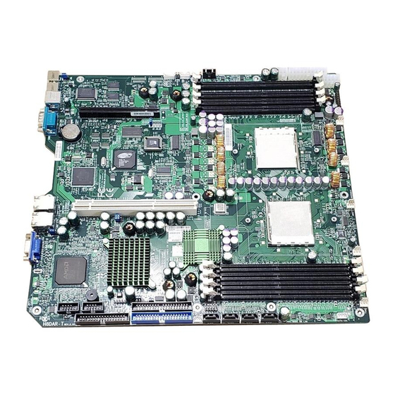
Page 9: H8Dar-T/H8Dar-E Image
Chapter 1: Introduction Figure 1-1. H8DAR-T/H8DAR-E Image... -
Page 10: H8Dar-T/H8Dar-E Serverboard Layout
JPS2 SPKR USB4 JPS1 CPU1 DIMM 1B COM2 JIDE#2 JBT1 USB2/3 FAN5 JS10 JFDD1 JIDE#1 M-SATA0 M-SATA1 M-SATA2 M-SATA3 JWOR Notes: Jumpers not indicated are for test purposes only. Serial ATA components, connectors and jumpers are for the H8DAR-T only. -
Page 11: H8Dar-T/H8Dar-E Quick Reference
Chapter 1: Introduction H8DAR-T/H8DAR-E Quick Reference Jumpers Description Default Setting 3rd Power Fail Signal En/Dis Open (Disabled) JBT1 CMOS Clear See Section 2-7 C1/2 C to PCI Enable/Disable Pins 1-2 (Enabled) JPG1 VGA Enable/Disable Pins 1-2 (Enabled) JLAN1/JLAN2 En/Disable Pins 1-2 (Enabled) -
Page 12: Serverboard Features
H8DAR-T/H8DAR-E User’s Manual Serverboard Features • Single or dual AMD dual-core Opteron 200 series 64-bit processors in 940-pin microPGA ZIF sockets Memory • Eight dual/single channel DIMM slots supporting up to 32 GB of registered ECC DDR333/266 or up to 16 GB of registered ECC DDR400 SDRAM Note: Memory capacities are halved for single CPU systems. - Page 13 • Internal/external modem ring-on Onboard I/O • Marvell 88SX6081 Serial ATA controller, supports four SATA ports (RAID0, 1 and JBOD supported, H8DAR-T only)* • Two (2) ATA133 IDE ports • One (1) fl oppy port interface (up to 2.88 MB) •...
-
Page 14: Amd-8132/8111 Chipset: System Block Diagram
H8DAR-T/H8DAR-E User’s Manual 184-pin DIMMs 184 -pin DIMMs 16 x 16 Hyper Transport (2000 MT/s) Opteron Opteron Processor (2) Processor (1) 144-bit, 200 -400 MT/s 144-bit, 200-400 MT/s 16 x 16 Hyper Transport (1200 MT/s) Marvell Broadcom 133 MHz PCI-X Slot... -
Page 15: Chipset Overview
Chapter 1: Introduction Chipset Overview The H8DAR-T/H8DAR-E serverboard is based on the AMD-8132 chipset. This chipset is composed of two main components: the AMD-8132 HyperTransport PCI-X Tunnel and the AMD-8111 HyperTransport I/O Hub. The AMD-8132 chipset provides high performance and an excellent feature-set for multi-proces- sor server solutions. -
Page 16: Pc Health Monitoring
H8DAR-T/H8DAR-E User’s Manual PC Health Monitoring This section describes the PC health monitoring features of the H8DAR-T/H8DAR- E. The serverboard has an onboard System Hardware Monitor chip that supports PC health monitoring. Onboard Voltage Monitors for the CPU core voltages, +3.3V, +5V, ±12V and Battery Voltage... -
Page 17: Power Confi Guration Settings
Chapter 1: Introduction Power Confi guration Settings This section describes the features of your serverboard that deal with power and power settings. Microsoft OnNow The OnNow design initiative is a comprehensive, system-wide approach to system and device power control. OnNow is a term for a PC that is always on but appears to be off and responds immediately to user or other requests. -
Page 18: Power Supply
It is even more important for processors that have high CPU clock rates of 1 GHz and faster. The H8DAR-T/H8DAR-E accommodates 12V ATX power supplies. Although most power supplies generally meet the specifi cations required by the CPU, some are inadequate. -
Page 19: Super I/O
Chapter 1: Introduction Super I/O The disk drive adapter functions of the Super I/O chip include a fl oppy disk drive controller that is compatible with industry standard 82077/765, a data separator, write pre-compensation circuitry, decode logic, data rate selection, a clock genera- tor, drive interface control logic and interrupt and DMA logic. -
Page 20: Chapter 2: Installation
Chapter 2: Installation Chapter 2 Installation Static-Sensitive Devices Electrostatic Discharge (ESD) can damage electronic com ponents. To prevent dam- age to your system board, it is important to handle it very carefully. The following measures are generally suffi cient to protect your equipment from ESD. Precautions •... -
Page 21: Processor And Heatsink Installation
H8DAR-T/H8DAR-E User's Manual Processor and Heatsink Installation Exercise extreme caution when handling and installing the proces- sor. Always connect the power cord last and always remove it be- fore adding, removing or changing any hardware components. Installing the CPU Backplates Two CPU backplates (BKT-0004) are included in the retail box. - Page 22 Chapter 2: Installation 4. With the CPU inserted into the socket, inspect the four corners of the CPU to make sure that it is properly installed and fl ush with the socket. 5. Gently press the CPU socket lever down until it locks in the plastic tab. For a dual-processor system, repeat these steps to install another CPU into the CPU#2 socket.
-
Page 23: Mounting The Serverboard Into A Chassis
1. Check the compatibility of the serverboard ports and the I/O shield The H8DAR-T/H8DAR-E serverboard requires a chassis that can support extended ATX boards of 12" x 13.05" in size. Make sure that the I/O ports on the serverboard align with their respective holes in the I/O shield at the rear of the chassis. - Page 24 Chapter 2: Installation Support The H8DAR-T/H8DAR-E supports single or dual-channel, registered ECC DDR400/333/266 SDRAM. Both interleaved and non-interleaved memory are supported, so you may populate any number of DIMM slots (see note on previous page and charts on following page). The CPU2 DIMM slots can only be accessed when two CPUs are installed (however, the CPU2 DIMM slots are not required to be populated when two CPUs are installed).
- Page 25 H8DAR-T/H8DAR-E User's Manual Populating Memory Banks for 128-bit Operation CPU1 CPU1 CPU1 CPU1 CPU2 CPU2 CPU2 CPU2 DIMM1A DIMM1B DIMM2A DIMM2B DIMM1A DIMM1B DIMM2A DIMM2B Notes: X indicates a populated DIMM slot. If adding at least four DIMMs (with two CPUs installed), the confi...
-
Page 26: I/O Port And Control Panel Connections
Chapter 2: Installation I/O Port and Control Panel Connections The I/O ports are color coded in conformance with the PC99 specifi cation to make setting up your system easier. See Figure 2-3 below for the colors and locations of the various I/O ports. Figure 2-3. -
Page 27: Connecting Cables
+3.3V +3.3V -12V +3.3V The primary power supply connector (J1B4) on the H8DAR-T/H8DAR-E PS_ON meets the SSI (Superset ATX) 24-pin specifi cation. Refer to the table on the right for the pin defi nitions of the ATX 24-pin power connector. -
Page 28: Power Led
Chapter 2: Installation Power LED Power LED Pin Defi nitions (JF1) The Power LED connection is located Pin# Defi nition on pins 15 and 16 of JF1. Refer to the table on the right for pin defi nitions. Control HDD LED HDD LED The HDD (IDE Hard Disk Drive) LED Pin Defi... -
Page 29: Power Fail Led
H8DAR-T/H8DAR-E User's Manual Power Fail LED Power Fail LED The Power Fail LED connection is Pin Defi nitions (JF1) located on pins 5 and 6 of JF1. Refer Pin# Defi nition to the table on the right for pin defi ni- tions. -
Page 30: Extra Usb Headers
Note: Pin 10 is included on the header but not on the port. NC indicates no connection. Fan Headers Fan Header Pin Defi nitions (FAN1-5) The H8DAR-T/H8DAR-E has five Pin# Defi nition headers (FAN1-FAN5). Fan speed is Ground (Black) controlled via Thermal Management with a BIOS setting. -
Page 31: Power Led/Speaker
H8DAR-T/H8DAR-E User's Manual Power LED/Speaker PWR LED Connector Pin Defi nitions (JD1) Pin# Defi nition On JD1, pins 1, 2, and 3 are for the +Vcc power LED and pins 4 through 7 are for the speaker. See the tables on the -Vcc right for pin defi... -
Page 32: Chassis Intrusion
Chapter 2: Installation Chassis Intrusion Chassis Intrusion Pin Defi nitions (JL1) A Chassis Intrusion header is located Pin# Defi nition at JL1. Attach the appropriate cable Intrusion Input to inform you of a chassis intrusion. Ground JLAN1/2 (Ethernet Ports) Two Gigabit Ethernet ports (desig- nated JLAN1 and JLAN2) are located beside the VGA port. -
Page 33: Overheat Led
H8DAR-T/H8DAR-E User's Manual Overheat LED (JOH1) Overheat LED Pin Defi nitions (JOH1) Connect an LED to the JOH1 header Pin# Defi nition to provide warning of chassis over- heating. See the table on the right OH Active for pin defi nitions. -
Page 34: Jumper Settings
Chapter 2: Installation Jumper Settings Explanation of Jumpers To modify the operation of the Connector serverboard, jumpers can be used to Pins choose between optional settings. Jumpers create shorts between two pins to change the function of the Jumper connector. Pin 1 is identifi ed with a square solder pad on the printed circuit board. -
Page 35: Jlan1/2 Enable/Disable
H8DAR-T/H8DAR-E User's Manual JLAN1/2 Enable/Disable JLAN1/2 Enable/Disable Jumper Settings (JPL) Change the setting of jumper JPL Jumper Setting Defi nition to enable or disable the JLAN1 and JLAN2 Gb Ethernet ports. See the Pins 1-2 Enabled table on the right for jumper settings. -
Page 36: Onboard Speaker Enable/Disable
Chapter 2: Installation Onboard Speaker Enable/ Disable The JD1 header allows you to use either an external speaker or the Onboard Speaker Enable/Disable internal (onboard) speaker. To use Pin Defi nitions (JD1) the internal (onboard) speaker, close Pins Defi nition pins 6 and 7 with a jumper. -
Page 37: Sata Firmware Flash
H8DAR-T/H8DAR-E User's Manual SATA Firmware Flash (H8DAR-T) SATA Firmware Flash Jumper Settings (JPS2) Jumper JPS2 is used to fl ash the fi rm- Jumper Setting Defi nition ware for the SATA controller. The de- Open Normal fault setting is open. See the table on... -
Page 38: Floppy, Ide And Sata Drive Connections
Chapter 2: Installation Floppy, IDE and SATA Drive Connections Use the following information to connect the fl oppy and hard disk drive cables. The fl oppy disk drive cable has seven twisted wires. A red mark on a wire typically designates the location of pin 1. A single fl... -
Page 39: Ide Connectors
H8DAR-T/H8DAR-E User's Manual IDE Connectors IDE Drive Connectors Pin Defi nitions (JIDE#1/JIDE#2) Pin# Defi nition Pin # Defi nition There are no jumpers to confi g- ure the onboard IDE#1 and #2 Reset IDE Ground connectors. See the table on... -
Page 40: 2-10 Enabling Sata Raid
Chapter 2: Installation 2-10 Enabling SATA RAID Now that the hardware is set up, you must now install the operating system and the SATA RAID drivers, if you wish to use RAID with your SATA drives. The installation procedure differs depending on whether you wish to have the operating system installed on a RAID array or on a separate non-RAID drive. - Page 41 H8DAR-T/H8DAR-E User's Manual Adaptec HostRAID Controller/Driver Adaptec's Embedded Serial ATA RAID with HostRAID controller adds RAID function- ality to the SATA I/O controller by supporting RAID 0 (Striping) or RAID 1 (Mirroring) to enhance the industry's pioneer PCI-to-e host controller products. RAID striping (RAID 0) can greatly improve hard disk I/O performance because of its capability in striping data across multiple drives.
- Page 42 Chapter 2: Installation Viewing Array Properties To view the properties of an existing array: 1. At the BIOS prompt, press <Ctrl+A>. 2. From the ARC menu, select Array Confi guration Utility (ACU). 3. From the ACU menu, select Manage Arrays. 4.
- Page 43 H8DAR-T/H8DAR-E User's Manual 2. From the ARC menu, select Array Configuration Utility Main Menu (ACU). 3. From the ACU menu select Create Array. 4. Select the disks for the new array and press <Insert>. Note: To deselect any disk, highlight the disk and press <Delete>.
- Page 44 Chapter 2: Installation 5. When fi nished, press Done (as shown on the following screen). Notes 1. Before adding a new drive to an array, back up any data contained on the new drive. Otherwise, all data will be lost. 2.
- Page 45 H8DAR-T/H8DAR-E User's Manual bootable? (Yes/No):" The bootable array will then be deleted and the asterisk will disappear. Note: do not use the delete key to delete a bootable array. Adding/Deleting Hotspares Note: In order to rebuild a RAID (RAID 0 or RAID 1), you need to add a new HDD as a hotspare.
-
Page 46: Using The Disk Utilities
Chapter 2: Installation 7. Read the warning message as shown on the screen below. 8. Make sure that you have selected the correct disk drives to initialize. If cor- rect, type Y to continue. Rebuilding Arrays Note 1: Rebuilding applies to Fault Tolerant arrays (RAID 1) only. If an array build process (or initialization) is interrupted or critical with one member missing, you must perform a rebuild to optimized its functionality. - Page 47 H8DAR-T/H8DAR-E User's Manual Notes 2-28...
-
Page 48: Chapter 3: Troubleshooting
Chapter 3: Troubleshooting Chapter 3 Troubleshooting Troubleshooting Procedures Use the following procedures to troubleshoot your system. If you have followed all of the procedures below and still need assistance, refer to the ‘Technical Support Procedures’ and/or ‘Returning Merchandise for Service’ section(s) in this chapter. Always disconnect the AC power cord before adding, changing or installing any hardware components. -
Page 49: Memory Errors
H8DAR-T/H8DAR-E User's Manual NOTE If you are a system integrator, VAR or OEM, a POST diagnostics card is recommended. For I/O port 80h codes, refer to App. B. Memory Errors 1. Make sure that the DIMM modules are properly and fully installed. -
Page 50: Frequently Asked Questions
Frequently Asked Questions Question: What type of memory does my serverboard support? Answer: The H8DAR-T/H8DAR-E supports up to 32 GB of registered ECC DDR333/266 or up to 16 GB of registered ECC DDR400 interleaved or non-inter- leaved SDRAM with two CPUs installed. With only one CPU installed the maximum memory support is halved. -
Page 51: Returning Merchandise For Service
H8DAR-T/H8DAR-E User's Manual Question: Why can't I turn off the power using the momentary power on/off switch? Answer: The instant power off function is controlled in BIOS by the Power Button Mode setting. When the Instant Off setting is enabled, the serverboard will have in- stant off capabilities as long as the BIOS has control of the system. -
Page 52: Chapter 4: Bios
Chapter 4 BIOS Introduction This chapter describes the AMIBIOS™ Setup utility for the H8DAR-T/H8DAR-E. The AMI ROM BIOS is stored in a fl ash chip and can be easily upgraded using a fl oppy disk-based program. Note: Due to periodic changes to the BIOS, some settings may have been added or deleted and might not yet be recorded in this manual. -
Page 53: Main Setup
H8DAR-T/H8DAR-E User's Manual Main Setup When you fi rst enter AMI BIOS Setup Utility, you will see the Main setup screen. You can always return to the Main setup screen by selecting the Main tab on the top of the screen. - Page 54 Chapter 4: BIOS IDE Confi guration Onboard PCI IDE Controller The following options are available to set the IDE controller status: Disabled will dis- able the controller. Primary will enable the primary IDE controller only. Secondary will enable the secondary IDE controller only. Both will enable both the primary and the secondary IDE controllers.
- Page 55 H8DAR-T/H8DAR-E User's Manual data transfer rate of 3.3 MBs. Select 1 to allow AMI BIOS to use PIO mode 1 for a data transfer rate of 5.2 MBs. Select 2 to allow AMI BIOS to use PIO mode 2 for a data transfer rate of 8.3 MBs. Select 3 to allow AMI BIOS to use PIO mode 3 for a data transfer rate of 11.1 MBs.
- Page 56 Chapter 4: BIOS Floppy Confi guration Floppy A Move the cursor to these fi elds via up and down <arrow> keys to select the fl oppy type. The options are Disabled, 360 KB 5 1/4", 1.2 MB 5 1/4", 720 KB 3½", 1.44 MB 3½”, and 2.88 MB 3½".
- Page 57 H8DAR-T/H8DAR-E User's Manual Parallel Port Address This option specifi es the I/O address used by the parallel port. Select Disabled to prevent the parallel port from accessing any system resources. When the value of this option is set to Disabled, the printer port becomes unavailable. Select 378 to allow the parallel port to use 378 as its I/O port address.
- Page 58 Chapter 4: BIOS BIOS --> AML ACPI Table When Enabled, BIOS-->AML exchange table pointer to be included in (X) REDT pointer list. Options are Enabled and Disabled. Headless Mode Select "Enabled" to activate the Headless Operation Mode through ACPI. The options are Enabled and Disabled.
- Page 59 H8DAR-T/H8DAR-E User's Manual CPU0: CPU1 HT Link1 Width The HT link will run at the width specifi ed in this setting. Options are Auto, 2 bit, 4 bit, 8 bit and 16 bit. CPU0: PCI-X0 HT Link1 Speed The HT link will run at the speed specifi ed in this setting if it is slower than or equal to the system clock and if the board is capable.
- Page 60 Chapter 4: BIOS System Health Monitor CPU Overheat Temperature Use the "+" and "-" keys to set the CPU temperature threshold to between 65 and 90 C. When this threshold is exceeded, the overheat LED on the chassis will light up and an alarm will sound. The LED and alarm will turn off once the CPU temperature has dropped to 5 degrees below the threshold set.
-
Page 61: Pci/Pnp Menu
H8DAR-T/H8DAR-E User's Manual PCI/PnP Menu Plug & Play OS Select Yes to allow the OS to confi gure Plug & Play devices. (This is not required for system boot if your system has an OS that supports Plug & Play.) Select No to allow AMIBIOS to confi... -
Page 62: Boot Menu
Chapter 4: BIOS DMA Channel 0/Channel 1/Channel 3/Channel 5/Channel 6/Channel Select Available to indicate that a specifi c DMA channel is available to be used by a PCI/PnP device. Select Reserved if the DMA channel specifi ed is reserved for a Legacy ISA device. -
Page 63: Boot Device Priority
H8DAR-T/H8DAR-E User's Manual Wait for ‘F1’ If Error Enable to activate the Wait for F1 if Error function. The options are Enabled and Disabled. Hit ‘DEL’ Message Display Enable to display the message telling the user to hit the DEL key to enter the setup utility. -
Page 64: Security Menu
Chapter 4: BIOS CD/DVD Drives This feature allows the user to specify the boot sequence from available CDROM drives. 1st Drive Specifi es the boot sequence for the 1st Hard Drive. Security Menu AMI BIOS provides a Supervisor and a User password. If you use both passwords, the Supervisor password must be set fi... -
Page 65: Chipset Menu
H8DAR-T/H8DAR-E User's Manual Chipset Menu North Bridge Confi guration Memory Confi guration Memclock Mode This setting determines how the memory clock is set. Auto has the memory clock set by the code and Limit allows the user to set a standard value. - Page 66 Chapter 4: BIOS ECC Confi guration DRAM ECC Enable DRAM ECC allows hardware to report and correct memory errors automatically. Options are Enabled and Disabled. MCA DRAM ECC Logging When "Enabled", MCA DRAM ECC logging and reporting is enabled. Options are Enabled and Disabled.
- Page 67 H8DAR-T/H8DAR-E User's Manual South Bridge Confi guration 2.0 SMBus Controller Allows the user to Enable or Disable the SMBus controller. HT Link0 P-Comp Mode Allows user to set values for this mode. Options are Auto (hardware compensa- tion values), Data (allows user to override auto values with an absolute value), CalComp + Data (allows user to add to the generated value) and CalComp - Data (allows user to subtract from the generated value).
-
Page 68: Power Menu
Chapter 4: BIOS Power Menu Power Button Mode Allows the user to change the function of the power button. Options are Instant Off and 4-Sec. Delay. Restore on AC Power Loss This setting allows you to choose how the system will react when power returns after an unexpected loss of power. -
Page 69: Exit Menu
H8DAR-T/H8DAR-E User's Manual Exit Menu Select the Exit tab from AMI BIOS Setup Utility screen to enter the Exit BIOS Setup screen. Save Changes and Exit When you have completed the system confi guration changes, select this option to leave BIOS Setup and reboot the computer, so the new system confi guration parameters can take effect. -
Page 70: Appendix A: Bios Error Beep Codes
Appendix A: BIOS Error Beep Codes Appendix A BIOS Error Beep Codes During the POST (Power-On Self-Test) routines, which are performed each time the system is powered on, errors may occur. Non-fatal errors are those which, in most cases, allow the system to continue the boot-up process. - Page 71 H8DAR-T/H8DAR-E User's Manual Notes...
-
Page 72: Appendix B: Bios Post Checkpoint Codes
Appendix B: BIOS POST Checkpoint Codes Appendix B BIOS POST Checkpoint Codes When AMIBIOS performs the Power On Self Test, it writes checkpoint codes to I/O port 0080h. If the computer cannot complete the boot process, diagnostic equipment can be attached to the computer to read I/O port 0080h. Uncompressed Initialization Codes The uncompressed initialization checkpoint codes are listed in order of execution: Checkpoint... - Page 73 H8DAR-T/H8DAR-E User's Manual Bootblock Recovery Codes The bootblock recovery checkpoint codes are listed in order of execution: Checkpoint Code Description The onboard fl oppy controller if available is initialized. Next, beginning the base 512 KB memory test. Initializing the interrupt vector table next.
- Page 74 Appendix B: BIOS POST Checkpoint Codes Uncompressed Initialization Codes The following runtime checkpoint codes are listed in order of execution. These codes are uncompressed in F0000h shadow RAM. Checkpoint Code Description The NMI is disabled. Next, checking for a soft reset or a power on condition. The BIOS stack has been built.
- Page 75 H8DAR-T/H8DAR-E User's Manual Checkpoint Code Description Interrupt vector initialization is done. Clearing the password if the POST DIAG switch is on. Any initialization before setting video mode will be done next. Initialization before setting the video mode is complete. Confi guring the mono- chrome mode and color mode settings next.
- Page 76 Appendix B: BIOS POST Checkpoint Codes Checkpoint Code Description The memory below 1 MB has been cleared via a soft reset. Clearing the memory above 1 MB next. The memory above 1 MB has been cleared via a soft reset. Saving the memory size next.
- Page 77 H8DAR-T/H8DAR-E User's Manual Checkpoint Code Description The password was checked. Performing any required programming before WIN- BIOS Setup next. The programming before WINBIOS Setup has completed. Uncompressing the WINBIOS Setup code and executing the AMIBIOS Setup or WINBIOS Setup utility next.
- Page 78 Appendix B: BIOS POST Checkpoint Codes Checkpoint Code Description Returned from adaptor ROM at E000h control. Performing any initialization required after the E000 option ROM had control next. Initialization after E000 option ROM control has completed. Displaying the system confi guration next. Uncompressing the DMI data and executing DMI POST initialization next.
- Page 79 H8DAR-T/H8DAR-E User's Manual (continued from front) The products sold by Supermicro are not intended for and will not be used in life support systems, medical equipment, nuclear facilities or systems, aircraft, aircraft devices, aircraft/emergency com- munication devices or other critical systems whose failure to perform be reasonably expected to result in signifi...
Need help?
Do you have a question about the Supero H8DAR-T and is the answer not in the manual?
Questions and answers