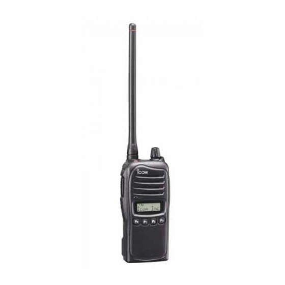
Icom IC-F3021S Service Manual
Vhf fm transceivers
Hide thumbs
Also See for IC-F3021S:
- Service manual addendum (105 pages) ,
- Manual (38 pages) ,
- Instruction manual (32 pages)
Table of Contents
Advertisement
Quick Links
Advertisement
Table of Contents

Related Manuals for Icom IC-F3021S


Summary of Contents for Icom IC-F3021S
- Page 1 SERVICE MANUAL VHF FM TRANSCEIVERS S-14303HZ-C1 July 2006...
- Page 2 8. READ the instructions of test equipment thoroughly before connecting equipment to the transceiver. Icom, Icom Inc. and logo are registered trademarks of Icom Incorporated (Japan) in the United States, the United Kingdom, Germany, France, Spain, Russia and/or other countries.
-
Page 3: Table Of Contents
TABLE OF CONTENTS SECTION SPECIFICATIONS SECTION INSIDE VIEWS SECTION DISASSEMBLY INSTRUCTIONS SECTION OPTIONAL UNIT INSTALLATION SECTION CIRCUIT DESCRIPITON RECEIVER CIRCUITS............5-1 TRANSMITTER CIRCUITS . - Page 4 50 Ω (nominal) • Antenna impedance • Operating temperature range −22˚F to +140˚F –25˚C to +55˚C • Power supply requirement Specified Icom’s battery packs only (Operatable voltage; 7.2 V DC negative ground) • Current drain Stand-by 75 mA (approx.) Max.audio...
- Page 5 SECTION 2 INSIDE VIEWS MAIN UNIT TOP VIEW BOTTOM VIEW +5 regulator Q26: 2SB1132 Q27: XP6501 Q28: UNR9213J AF amplifier (IC15: TA7368FG) CPU5 regulator TX VCO (IC17: NJM2870) Q16: 2SC5006 IF amplifier D10, D13, D34: (Q7: 2SC5107) 1st mixer HVC375B (Q6: 3SK324) PLL IC RX VCO...
-
Page 6: Disassembly Instructions
SECTION 3 DISASSEMBLY INSTRUCTIONS 1 REMOVING THE CHASSIS UNIT q Unscrew ANT nut A, and remove knob B. e Unscrew 6 screws J. w Unscrew 2 screws C, and remove the jack panel. r Remove the side plate I. e Unscrew 2 screws D, and unplug the connector E from t Unsolder 8 points K, and remove the shield cover. - Page 7 SECTION 4 OPTIONAL UNIT INSTALLATION CAUTION! Optional unit installation should be done at authorized Icom servise center only. Install the optional unit as follows. r Install the unit as below. q Rotate [VOL] to turn the power OFF, and remove the battery pack.
-
Page 8: Circuit Descripiton
SECTION 5 CIRCUIT DESCRIPTION 5-1 RECEIVER CIRCUITS The converted 1st IF signal is passed through the 1st IF fi lter (FI1) to filter-out adjacent signals, then applied to the 1st IF 5-1-1 ANTENNA SWITCHING CIRCUIT (PA UNIT) amplifi er (Q7). The amplifi ed 1st IF signal is then applied to the The antenna switching circuit toggles the receive (RX) line and FM IF IC (IC9, pin 16). -
Page 9: Transmitter Circuits
The AF signals from the analog switch (IC3, pin 11) are 5-2 TRANSMITTER CIRCUITS applied to the volume buffer amplifi er (IC6, pin 9). The buffer- 5-2-1 MICROPHONE AMPLIFIER CIRCUITS amplified AF signals are adjusted its level (= audio level) (MAIN UNIT) by volume control pot (R315), then applied to the AF power The AF signals from the microphone (MIC signals) are fi... - Page 10 5-2-3 TRANSMIT AMPLIFIERS (PA UNIT) 5-2-4 APC CIRCUIT (PA UNIT) The transmit signal from the VCO is amplifi ed to the transmit The APC (Automatic Power Control) circuit prevents the output level by the transmit amplifi ers. transition of the transmit output power level which is caused by load mismatching or heat effect, etc.
-
Page 11: Pll Circuits
5-3 PLL CIRCUITS 5-3-2 PLL IC (MAIN UNIT) The PLL circuit provides stable oscillation of the transmit 5-3-1 VOLTAGE CONTROLLED OSCILLATORS frequency and receive 1st LO frequency. The PLL output (VCOs; MAIN UNIT) frequency is controlled by the divided ratio (N-data) from the VCO is an oscillator whose oscillating frequency is controlled CPU. -
Page 12: Power Supply Circuits
5-4 POWER SUPPLY CIRCUITS Voltage from the attached battery pack is routed to whole of the circuit in the transceiver via a switch and regulators. Power switch F701 (PA unit ) Drive amplifier (Q702), Power amplifier (Q701), etc. IC17 CPU (IC22), CPU5 CPU5V EEPROM (IC10),... -
Page 13: Port Allocations
5-5 PORT ALLOCATIONS Port Description Name 5-5-1 CPU (IC22) Outputs Analog/Digital select signal to the A/D Port Description DIGI switch (D2, D3). Name “High”=Digital mode is selected. KR1− 1−3 Input ports for dealer-programmable keys. Outputs serial data to the LCD driver (IC20, pin 48). LSCK Outputs clock signal to the LCD driver (IC20, pin 47). -
Page 14: Adjustment Procedures
[Next>] to install the software to the destination folder. (e.g. items as below. C:\Program Files\Icom\CS-F3020 ADJ) t Set or modify adjustment data as specifi ed. y After the installation is completed, the “InstallShield Wiz- ard Complete”... - Page 15 • CONNECTION Attenuator Osciiloscope 10 dB or 20 dB deviation meter Standard signal generator 0.1 µV to 32 mV RF power meter (–127 dBm to –17 dBm) 0.1–10 W/50 CAUTION! Frequency DO NOT transmit while counter the SSG is connected to OPC-478 (RS-232C type) the antenna connector to RS-232C port...
- Page 16 • PC SCREEN EXSAMPLE Transmit output power (Hi) Reference frequency Receive sensitivity (Automatically) Transmit output power (L2) Receive sensitivity (Manually) Transmit output power (L1) Modulation balance PLL lock voltage FM deviation (Narrow) PLL lock voltage preset FM deviation (Middle*/Wide) S-meter PLL lock voltage (verify) CTCSS/DTCS deviation Squelch...
- Page 17 6-2 FREQUENCY ADJUSTMENT Select an adjustment item using [↑] / [↓] keys, then set to the specifi ed value using [←] / [→] keys on the connected PC’s keyboard. MEASUREMENT ADJUSTMENT ADJUSTMENT CONDITION VALUE UNIT OPERATION PLL LOCK 1 • Channel : CH 1 Click [Reload (F5)] button, then 3.5 V...
-
Page 18: Transmit Adjustment
6-3 TRANSMIT ADJUSTMENT Select an adjustment item using [↑] / [↓] keys, then set to the specifi ed value using [←] / [→] keys on the connected PC’s keyboard. MEASUREMENT ADJUSTMENT ADJUSTMENT CONDITION VALUE UNIT OPERATION OUTPUT 1 • Channel : CH 3 Connect an RF power meter to 5.0 W... -
Page 19: Receive Adjustment
6-4 RECEIVE ADJUSTMENT Select an adjustment item using [↑] / [↓] keys, then set to the specifi ed value using [←] / [→] keys on the connected PC’s keyboard. MEASUREMENT ADJUSTMENT ADJUSTMENT CONDITION VALUE UNIT LOCATION RECEIVE NOTE: “RECEIVE SENSITIVITY” must be adjusted before “S-METER.” Otherwise, “S-METER” will not be SENSITIVITY adjusted properly. -
Page 20: Main Unit
SECTION 7 PARTS LIST [MAIN UNIT] [MAIN UNIT] ORDER ORDER DESCRIPTION DESCRIPTION LOCATION LOCATION 1140005991 S.IC MB15A02PFV1-G-BND-ERE1 81.2/34.5 6200007850 S.COL ELJNC R82K-F 88.7/26.1 1130011770 S.IC CD4066BPWR 40.4/22 6200011031 S.COL ELJRF R10JFB 80.2/23 1110005320 S.IC NJM13403V-TE1 40.4/12.8 6200011031 S.COL ELJRF R10JFB 77.8/28.2 1110006350 S.IC LM2902PWR... - Page 21 [MAIN UNIT] [MAIN UNIT] ORDER ORDER DESCRIPTION DESCRIPTION LOCATION LOCATION 7030007340 S.RES ERJ2GEJ 153 X (15 k 79.6/34.7 R226 7030005300 S.RES ERJ2GEJ 150 X (15) 94.5/16 R100 7030005040 S.RES ERJ2GEJ 472 X (4.7 k 74.4/21.6 R227 7030009140 S.RES ERJ2GEJ 272 X (2.7 k 97.4/22.5 R101 7030004990 S.RES ERJ2GEJ 221 X (220)
- Page 22 [MAIN UNIT] [MAIN UNIT] ORDER ORDER DESCRIPTION DESCRIPTION LOCATION LOCATION 4030017430 S.CER ECJ0EC1H101J B 100.4/40.4 C161 4030017620 S.CER ECJ0EC1H100C 78.6/28 4030017360 S.CER ECJ0EC1H030B 97.4/39.5 C162 4030017500 S.CER ECJ0EC1H560J 82.4/23.3 4030017580 S.CER ECJ0EC1H060C 95.8/36.5 C163 4030017570 S.CER ECJ0EC1H040B 84.4/23.3 4030017460 S.CER ECJ0EB1E102K 90/34.5 C164 4030017590 S.CER ECJ0EC1H070C...
- Page 23 [MAIN UNIT] [MAIN UNIT] ORDER ORDER DESCRIPTION DESCRIPTION LOCATION LOCATION C315 4030016930 S.CER ECJ0EB1A104K 43.2/37 6450002250 CNR HSJ1456-010320 C316 4030017420 S.CER ECJ0EC1H470J 53.3/32 6450000131 CNR HSJ1102-018540 C317 4030016790 S.CER ECJ0EB1C103K 55/33 6510025220 S.CNR AXK540145J 16.3/10.3 C318 4030018140 S.CER ECJ0EB1H391K 60.2/31 C319 4030017760 S.CER ECJ0EB1H222K 58.4/32...
-
Page 24: Ant Unit
[PA UNIT] [CONNECT UNIT] ORDER ORDER DESCRIPTION DESCRIPTION LOCATION LOCATION C701 4030017460 S.CER ECJ0EB1E102K 35/11 L901 6200006190 S.COL BLM21PG300SN1D 8.7/6 C702 4030017430 S.CER ECJ0EC1H101J 33.8/10 C703 4030017420 S.CER ECJ0EC1H470J 34.8/10 C704 4030017390 S.CER ECJ0EC1H180J 32.3/10 C901 4030017460 S.CER ECJ0EB1E102K 5.6/6 C705 4030007040 S.CER C1608 CH 1H 180J-T 31.3/14.5... - Page 25 [MAIN UNIT] • BC-160 (Optional product) [MAIN UNIT] ORDER DESCRIPTION LOCATION ORDER DESCRIPTION 7030000010 S.RES MCR10EZHJ JPW 40.1/38.7 LOCATION 7030000010 S.RES MCR10EZHJ JPW 4.9/49.5 1110006480 S.IC NJM2801U1-0543-TE1 10.2/62.3 7030003560 S.RES ERJ3GEYJ 103 V (10 k 8.2/13.6 1110003071 S.IC µPC494GS-E1-A 13/36.7 7030000100 S.RES MCR10EZHJ 4R7 (4.7) 10.2/45.1 1140012301 S.IC...
-
Page 26: Connect Unit
SECTION 8 MECHANICAL PARTS AND DISASSEMBLY [CHASSIS PARTS] [PA UNIT] REF. ORDER REF. ORDER DESCRIPTION QTY. DESCRIPTION QTY. 6910015910 Connector ANT connector-104 J701 6910017680 Connector IMSA-9230B-1-04Z140-PT1 6910015860 Connector IMSA-6277S-02A-G J702 6910017680 Connector IMSA-9230B-1-04Z140-PT1 2510001060 Speaker K036NA500-47 MP701* 8410002530 2681 PA heatsink 8900009640 Cable OPC-963 [ANT UNIT]... - Page 27 * MP2 (C), MP12 (C): The shape is depending on the version. Unit: mm (inch) MP13 (C) MP25 (C) J1 (C) SP1 (C) MP35 (C) W1 (C) MP8 (C) MP24 (C) MP31 (C) MP1 (C) ANT Unit MP17 (C) MP801 (A) MP20 (C) MP33 (C) MP12* (C)
- Page 28 SECTION 9 SEMICONDUCTOR INFORMATION • TRANSISTORS AND FET's • DIODES 2SC5006 T1 HVC376B 2SA1577 T106 R 2SB1132 T100 R 2SC4081 T106 R 2SC4116 BL 1SV239 1SV307 DAN222TL HVC375B (Symbol: 24) (Symbol: B9) (Symbol: HR) (Symbol: BAR) (Symbol: BR) (Symbol: LL) (Symbol: TC) (Symbol: TX) (Symbol: N)
- Page 29 SECTION 10 BOARD LAYOUTS • MAIN UNIT (TOP VIEW) SWITCH H100 H105 to SPEAKER “SP1” (CHASSIS) • ANT UNIT (TOP VIEW) • PA UNIT (TOP VIEW) • BC-160 (TOP VIEW) (CHASSIS) • CONNECT UNIT (TOP VIEW) J901 to PA unit (No patterns) to Battery Connector “J2”...
- Page 30 • MAIN UNIT (BOTTOM VIEW) SIDE1 SIDE2 SIDE3 ISENS PA unit “J702” VR & POWER SWITCH to PA unit SPEAKER “J701” H105 H100 • PA UNIT (BOTTOM VIEW) J702 CONNECT unit ISENS to ANT unit “J901” to MAIN unit • ANT UNIT (BOTTOM VIEW) •...
- Page 31 SECTION 11 BLOCK DIAGRAM Q18: XP1214 Q19: UNR9213J MAIN UNIT 2SC4116 136-174MHz RIPPLE LVIN D9 : HVC376B PA UNIT BUFF D11: HVC375B D16:1SV307 RX VCO D33: HVC376B D17: MA2S077 RLVA 2SC5006 2SC5006 2SK880 15.3 MHz D701: 1SV307 TX/RX BUFF BUFF D704: 1SV307 Q704 Q702...
- Page 32 SECTION 12 VOLTAGE DIAGRAMS 12 - 1...
- Page 33 CONNECT UNIT J901 L901 BLM21P300S BATTERY CONNECTOR F701 0467003.NR TX: 7.20V TX: 6.92V RX: 7.23V RX: 7.23V TO CONNECT UNIT J901 R714 0.15 Q705 XP6401 TX: 2.25V RX: 0V Q706 Q704 J701 C731 2SC4081 2SC5006 TO MAIN UNIT EP712 MMZ1608Y102BT Q701 RD07MVS1 Q702...
- Page 34 SECTION 13 BC-160 [CHASSIS PARTS] RSQ035P03TR REF. ORDER DESCRIPTION QTY. 100µ CHARGE 8010019750 2830 case 8110008220 2830 cover 8930039620 Leg cushion (A) 2SC4081 1SS355 Screw PH BT M3 × 6 NI-ZU 8810008630 2SC4081 VSENS 5.00V battery 4.7k 9.6uS 10.05V MCR10-JPW 16.0V NJM2801U1-0543-TE1 MCR10-JPW...
- Page 35 Phone : +34 (93) 590 26 70 Fax : +34 (93) 589 04 46 Glenwood Centre #150-6165 : http://www.icomspain.com Highway 17 Delta, B.C., V4K 5B8, Canada E-mail : icom@icomspain.com Phone : +1 (604) 952-4266 Fax : +1 (604) 952-0090 : http://www.icomcanada.com E-mail : info@icomcanada.com Unit 9, Sea St., Herne Bay, Kent, CT6 8LD, U.K.
- Page 36 S-14303HZ-C1 1-1-32, Kamiminami, Hirano-ku, Osaka 547-0003, Japan © 2006 Icom Inc.
Need help?
Do you have a question about the IC-F3021S and is the answer not in the manual?
Questions and answers