Table of Contents
Advertisement
NOTE:
Please read all instructions
carefully before using this
product
Table of Contents
Safety Notice
Hardware Identifier
Assembly Instruction
Parts List
Warranty
Ordering Parts
Model
MD-389
Retain This
Manual for
Reference
07-29-09
OWNER'S
MANUAL
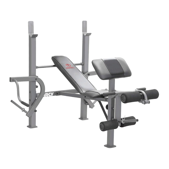
MARCY DIAMOND ELITE
WEIGHT BENCH
2801 S. Towne Ave., Pomona, CA 91766
Tel: (800) 999-8899 Fax: (626) 961-9966
www.impex-fitness.com
info@impex-fitness.com
MD-389
®
IMPEX
INC.
Advertisement
Table of Contents

Related Manuals for Impex MARCY DIAMOND ELITE MD-389


Summary of Contents for Impex MARCY DIAMOND ELITE MD-389
-
Page 1: Impex Inc
NOTE: Please read all instructions carefully before using this product Table of Contents MARCY DIAMOND ELITE Safety Notice WEIGHT BENCH Hardware Identifier MD-389 Assembly Instruction Parts List Warranty Ordering Parts Model MD-389 Retain This Manual for Reference 07-29-09 OWNER'S MANUAL ®... -
Page 2: Table Of Contents
ASSEMBLY INSTRUCTIONS................EXPLODED DIAGRAM.................……... PARTS LIST…………………………………………………………………………. WARRANTY....................… ORDERING PARTS..................BEFORE YOU BEGIN Thank you for selecting the MARCY DIAMOND ELITE Weight Bench MD-389 ® by IMPEX INC. For your safety and benefit, read this manual carefully before using the machine. -
Page 3: Important Safety Notice
IMPORTANT SAFETY NOTICE PRECAUTIONS This exercise machine is built for optimum safety. However, certain precautions apply whenever you operate a piece of exercise equipment. Be sure to read the entire manual before you assemble or operate your machine. In particular, note the following safety precautions: 1. -
Page 4: Warning Label Placement
WARNING LABEL PLACEMENT The Warning Label shown here has been placed on the Cross Brace. If the label is missing or illegible, please call customer service at 1-800-999-8899 for replacement. Apply the label in location shown. -
Page 5: Hardware Identifier
HARDWARE PACK NOTE: The following parts are not drawn to scale. Please use your own ruler to measure the size. -
Page 6: Assembly Instruction
ASSEMBLY INSTRUCTION Tools Required for Assembling the Machine: Two Adjustable Wrenches and Allen Wrenches. NOTE: It is strongly recommended that two or more people assemble this machine to avoid possible injury. STEP 1 (See Diagram 1) A.) Do not tighten Nuts and Bolts until instructed to do so. B.) Connect the Right &... - Page 7 STEP 2 (See Diagram 2) A.) Do not tighten Nuts and Bolts until instructed to do so. B.) Attach Main Seat Support (#3) to the Cross Brace (#4). Secure it with a 4 3/8” x 3 3/8” Bracket (#12), two M10 x 2 ½” Carriage Bolts (#35), two ¾” Washers (#45), and two M10 Aircraft Nuts (#47).
- Page 8 STEP 3 (See Diagram 3) A.) Attach the Leg Developer (#7) to the Front Post (#5). Secure it with one M10 x 2 ¾” Allen Bolt (#36), two ¾” Washers (#45), and one M10 Aircraft Nut (#47). B.) Attach the Arm Curl Handle (#14) to the open bracket on Leg Developer. Secure it with a L- shaped Lock Pin (#26).
- Page 9 STEP 4 (See Diagram 4) A.) Attach the two side-holes on the two Backrest Supports (#10) to the pivot on the Main Seat Support (#3). Place the other end of Backrest Supports against the Backrest Adjustment Bar (#9) B.) Place the Backrest Board (#17) onto the Backrest Supports. Secure it with four M6 x 1 ½”...
- Page 10 STEP 5 (See Diagam5) A.) Insert two Foam Tubes (#11) halfway through the holes on Leg Developer (#7). Push four Foam Rolls (#20) onto the Tubes from both ends. B.) Attach a Spring Clip (#21) to the weight post on Leg Developer and Butterfly. DIAGRAM 5...
-
Page 12: Parts List
PARTS LIST KEY NO. DESCRIPTION Q’ty Right Upright Beam Left Upright Beam Main Seat Support Cross Brace Front Post Arm Curl Stand 1 Leg Developer Diagonal Support Backrest Adjustment Bar Backrest Support Foam Tube 4 3/8” x 3 3/8” Bracket 4 ¾”... -
Page 13: Impex Inc
® IMPEX INC. LIMITED WARRANTY ® IMPEX Inc. ("IMPEX ") warrants this product to be free from defects in workmanship and material, under normal use and service conditions, for a period of two years on the Frame from the date of purchase. This warranty extends only to the original purchaser.
Need help?
Do you have a question about the MARCY DIAMOND ELITE MD-389 and is the answer not in the manual?
Questions and answers